1
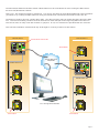
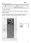
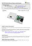
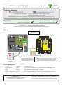
29/06/2011
Paxton
Ins-30001 Net2 485 TCP/IP Ethernet interface (Rev4)
Technical Support
01273 811011
[email protected]
Technical help is available:
Monday - Friday from 07:00 - 19:00 (GMT)
Saturday from 09:00 - 13:00 (GMT)
Documentation on all Paxton products can be found on our website - http://www.paxton.co.uk/
Suitability
DHCP compatible
(fixed IP recommended)
Connect over LAN, WAN or VPN
**IMPORTANT - THIS IS A NETWORK DEVICE**
Please contact your IT Administrator before installing this product
Fitting
Switchable 120 ohm
resistors
http://paxton.info/107
PLACE SERIAL
NUMBER
123456
LABEL
HERE
0889
Po w e r
+12V
0V
Re l ay 1
Reader 2
Net2 classic
Re d 1 2 V d c
Data
Ke y p a d 1
Load
Re d LED
5
0V out
Gr e e n LED
Media Detect
1
Am b e r LED
Clock/D1
Cl o ck / D 1
6
Re a d e r 1
Green LED
Data/D0
Dat a/ D0
Amber LED
Ca u t i o n : Fo r 1 2 V d . c r e a d e r s o n l y. Fo r co r r e ct
co n n e ct i o n o f o l d 5 V r e a d e r s r e f e r t o
i n st r u ct i o n s
Reset to DHCP
mode
Me d i a D e t e c t
Keypad 2
Red LED
0 V ou t
Red 12V dc
Lo a d
4
Dat a
3
Cl o ck
2
0V
Re l ay 2
12V
Clock
2
White/O rang e
3
Orang e
4
Ne t w o r k
1
Green
CAT5 ca b l e co d i n g
White/Green
I nput s
Screen or spare cores from
network cable
T
To next ACU
Unswitched
fused spur
The interface plugs directly
into the TCP/IP Ethernet
network via a standard
RJ45 connection box.
To reset the unit to DHCP, power up with
the reset button held down until the unit
beeps. The interface is now fully reset
and will now operate in DHCP mode.
LED indications
1.
2.
3.
4.
5.
6.
Power
Termination
Rx
Tx
Server Connected
Server Link
(Green)
- 12V power LED.
(Red)
- The on-board resistors are in place across the RS485 data pairs.
(Red)
- The interface is receiving data (RS485).
(Green)
- The interface is sending data (RS485).
(Green)
- The TCP/IP interface is communicating with the PC Net2 server.
Green = 100 Mbit/s : Orange = 10 Mbit/s (TCP/IP speed).
**IMPORTANT**
Apply power to the unit after connecting
the RJ45 plug to a network point.
This device requires Net2 v4.07 or later to operate.
Earlier Net2 software is not compatible with this unit.
If your PC can only support Net2 v3 software, please
contact Technical Support for further advice.
Page 1
The Net2 TCP/IP Ethernet Interface allows a Net2 data line to be controlled from a PC running the Net2 Server
across a TCP/IP Ethernet network.
There is a 1 km maximum length for a data line. This can be increased by using Net2 RS485 high speed repeaters
(477-836) or by creating multiple data lines using several Ethernet connections controlled from the one PC.
The data line must be wired in a single daisy chain. The data converter may be located anywhere along the data
line. 120 ohm terminating resistors must be linked across each data pair at the beginning AND end of the line.
This can be done on many units with a switch or jumpers. If not, free resistors are provided with the converter.
This unit has termination resistors that may be brought in circuit by means of a slide switch.
Remote Site 1
0V
Re d 1 2 V d c
http://paxton.info/107
PLACE SERIAL
NUMBER
123456
LABEL
HERE
0889
Po w e r
Net2 classic
0V
Re l ay 1
Cl o ck / D 1
Ke y p a d 1
Data
Dat a/ D0
0V out
Load
Re d LED
Re a d e r 1
Media Detect
+12V
Reader 2
Ca u t i o n : Fo r 1 2 V d . c r e a d e r s o n l y. Fo r co r r e ct
co n n e ct i o n o f o l d 5 V r e a d e r s r e f e r t o
i n st r u ct i o n s
Amber LED
Clock/D1
Gr e e n LED
Keypad 2
Red LED
Green LED
Data/D0
Am b e r LED
Me d i a D e t e c t
0 V ou t
Red 12V dc
Lo a d
Dat a
Cl o ck
Termination
Re l ay 2
12V
Remote Site 2
Termination switch ON
Clock
2
3
Orang e
4
Ne t w o r k
1
Green
White/O rang e
CAT5 ca b l e co d i n g
RS485 data line
White/Green
I nput s
Screen or spare cores from
network cable
T
TCP/IP Network
LAN/WAN
12V
Am b e r LED
Re d LED
0V out
Ke y p a d 1
Data
Re d 1 2 V d c
Po w e r
Net2 classic
0V
Re l ay 1
http://paxton.info/107
PLACE SERIAL
NUMBER
123456
LABEL
HERE
0889
Re l ay 2
Re a d e r 1
Media Detect
Load
+12V
Reader 2
Ca u t i o n : Fo r 1 2 V d . c r e a d e r s o n l y. Fo r co r r e ct
co n n e ct i o n o f o l d 5 V r e a d e r s r e f e r t o
i n st r u ct i o n s
Clock/D1
Dat a/ D0
Keypad 2
Amber LED
Gr e e n LED
Cl o ck / D 1
Me d i a D e t e c t
0 V ou t
Lo a d
Dat a
Cl o ck
Red 12V dc
Red LED
Green LED
Data/D0
0V
Clock
Po w e r
0V
Re l ay 1
http://paxton.info/107
PLACE SERIAL
NUMBER
123456
LABEL
HERE
0889
Re l ay 2
Po w e r
Gr e e n LED
Am b e r LED
Re d LED
Re d 1 2 V d c
Dat a/ D0
Ke y p a d 1
Ke y p a d 1
I nput s
PLACE SERIAL
NUMBER
123456
LABEL
HERE
0889
Po w e r
+12V
0V
Re l ay 1
Po w e r
Re l ay 1
Re l ay 2
Gr e e n LED
Am b e r LED
http://paxton.info/107
Re d LED
0V out
Ke y p a d 1
Ke y p a d 1
Data
Reader 2
Net2 classic
Re d 1 2 V d c
Re a d e r 1
Media Detect
Load
Ca u t i o n : Fo r 1 2 V d . c r e a d e r s o n l y. Fo r co r r e ct
co n n e ct i o n o f o l d 5 V r e a d e r s r e f e r t o
i n st r u ct i o n s
PC running Net2 software
Cl o ck / D 1
Amber LED
Clock/D1
Me d i a D e t e c t
Keypad 2
Red LED
Green LED
Data/D0
Dat a/ D0
Red 12V dc
0V
0 V ou t
+12V
T
Re l ay 2
4
Lo a d
0889
3
Orang e
Dat a
PLACE SERIAL
NUMBER
123456
LABEL
HERE
1
2
White/O rang e
Cl o ck
Am b e r LED
http://paxton.info/107
Re d LED
0V out
Reader 2
Net2 classic
White/Green
Green
Re d 1 2 V d c
Re a d e r 1
Media Detect
Ca u t i o n : Fo r 1 2 V d . c r e a d e r s o n l y. Fo r co r r e ct
co n n e ct i o n o f o l d 5 V r e a d e r s r e f e r t o
i n st r u ct i o n s
Amber LED
Dat a/ D0
Keypad 2
Red LED
Clock/D1
Gr e e n LED
Cl o ck / D 1
Me d i a D e t e c t
0 V ou t
Lo a d
Dat a
Cl o ck
Red 12V dc
I nput s
T
Ne t w o r k
4
Screen or spare cores from
network cable
CAT5 ca b l e co d i n g
Orang e
Ne t w o r k
3
CAT5 ca b l e co d i n g
1
2
White/O rang e
Clock
Clock
Termination
T
White/Green
1
Green
2
White/O rang e
3
Orang e
4
Ne t w o r k
3
4
CAT5 ca b l e co d i n g
2
Orang e
Ne t w o r k
1
Green
White/O rang e
CAT5 ca b l e co d i n g
White/Green
Screen or spare cores from
network cable
I nput s
Screen or spare cores from
network cable
I nput s
Data
Cl o ck / D 1
0V out
Data
+12V
Reader 2
Net2 classic
Clock
White/Green
Green
Load
Re a d e r 1
Media Detect
Load
Clock
Green LED
Ca u t i o n : Fo r 1 2 V d . c r e a d e r s o n l y. Fo r co r r e ct
co n n e ct i o n o f o l d 5 V r e a d e r s r e f e r t o
i n st r u ct i o n s
Clock/D1
0889
Screen or spare cores from
network cable
Data/D0
Keypad 2
Red LED
Green LED
Data/D0
Me d i a D e t e c t
PLACE SERIAL
NUMBER
123456
LABEL
HERE
0 V ou t
Red 12V dc
0V
Amber LED
http://paxton.info/107
Lo a d
+12V
Reader 2
Net2 classic
Dat a
Cl o ck
Am b e r LED
Re d LED
Re a d e r 1
0V out
Re d 1 2 V d c
Dat a/ D0
Ca u t i o n : Fo r 1 2 V d . c r e a d e r s o n l y. Fo r co r r e ct
co n n e ct i o n o f o l d 5 V r e a d e r s r e f e r t o
i n st r u ct i o n s
Media Detect
Gr e e n LED
Cl o ck / D 1
Me d i a D e t e c t
Clock/D1
Data
0 V ou t
Keypad 2
Amber LED
Load
Lo a d
Dat a
Cl o ck
Red 12V dc
Red LED
Green LED
Data/D0
RS485 data line
T
Re l ay 1
4
Re l ay 2
3
Orang e
Ne t w o r k
1
2
White/O rang e
CAT5 ca b l e co d i n g
White/Green
Green
I nput s
Screen or spare cores from
network cable
T
Termination
Page 2
When connecting to a LAN
The IP address should be assigned a fixed value, or should be given a DHCP reservation. Unreserved IP addresses
issued by DHCP servers are not guaranteed to be constant, leading to potential failure of communication between
Net2 software and the device.
Run the Net2 Server Configuration Utility (Start/Programs/Net2) and Click on TCP/IP nodes.
Click on;Detect and the MAC address of the device(s) will appear in the table. You must then use the "IP address
configuration" tab to manually assign the IP address, subnet mask and gateway.
Be aware that if the IP address that you give the device is not in the same IP range as the PC, the device will no
longer respond until you connect to it with a PC that is in the same IP range.
Some firewall/virus protection software and other wireless hardware can block the IP detection process. Disable
these and try to detect the device again. Please contact Technical Support if you require further advice.
Page 3
If you detect the MAC address but the device now shows 'Not Responding', you must check the IP address, to
make sure it is still in range with the PC or network. If it is not, you should either change the IP address of the
PC or the IP address of the device so they are both again in the same range. Our Technical team can talk you
through this if you need help.
If the MAC address does not appear when you click;Detect, ensure that the following ports are open on all devices
between this unit and the Net2 PC:9999
TCP
10001
TCP
30718
UDP
If you still cannot detect the MAC address of the device, call our Technical Support Help line.
Connecting to a WAN or different subnet mask
If you are connecting this device to a remote subnet which is different from the Net2 software PC, the standard
detect mechanism cannot work across the network routers between them. The IP address, along with the correct
subnet mask and gateway for the remote subnet have to be set. Either do this on the local subnet with the
existing Net2 PC, or use a PC on the remote subnet once the device is installed.
The PC that has the Net2 server installed must be able to access the IP address range on the WAN/remote site.
This may require the routers and gateways to be configured between the networks. Again, this would be done by
the Network administrator of that site. Make sure the ports listed above are open on all intermediate routers.
Once installed, create a record with the;Add button (if none was created during initial set up) and you should then
be able to detect its MAC by entering the IP address in the Configuration screen Ping box.
Naming TCP/IP Ethernet interfaces
The rename button can be used to give an interface a meaningful name in the system. This can be especially
useful when more than one interface is used. The name will appear in the doors screen within Net2 showing which
ACU's are connected to which data line, helping in any future fault finding process.
TCP/IP Loopback test
The following test should be run if there are problems setting up the IP configuration of the interface. This test
sends data to the device and checks this against the data it receives back. This confirms that the network is
working correctly.
The Net2 server program must be shut down during this test.
Remove any wires from the RS485 data line connector and create a hardwired data loop as follows. Connect
the Orange to White/Green and Green to White/Orange. To run the test, go to Net2 Server Config Utility/TCP/
IP Nodes/Advanced and click on Loopback test. If the test fails, connect the unit directly to the PC with an RJ45
patch cable and test it again. Should this still fail, please call Technical Support for further advice.
Specifications
Electrical
Voltage
Min
Max
11V DC
14V DC
250 mA
Current
Min
Max
ACU per data line
1
200
Max 500 per system
Data lines per PC
1
100
Net2 v4.14
10 Mbit/s
100 Mbit/s
Environment
Ethernet network speed
200 kbit/s
Ethernet bandwidth requirement
Yes
DHCP support (fixed IP recommended)
115.2 kbit/s
RS485 network speed
Operating temperature
Waterproof
Dimensions
-20 °C
+55 °C
NO - If used externally, it must be protected in a plastic weatherproof housing
Width
Height
Depth
170 mm
175 mm
40 mm
This product is not suitable for retail sale. All warranties are invalid if this product is not installed by a competent person.
Page 4