1
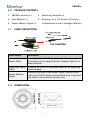
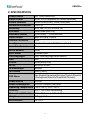
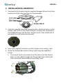
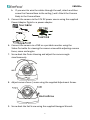
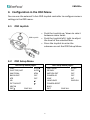
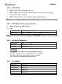
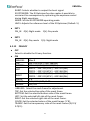
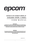
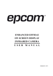
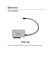
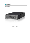
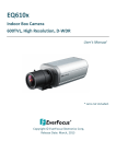
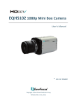
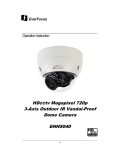
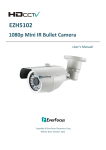
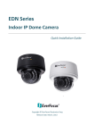
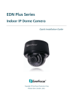
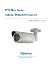
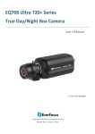
EBD431e Indoor/Outdoor Ball Camera 700TVL, 3‐Axis, IP66, IR User’s Manual Copyright © EverFocus Electronics Corp, Release Date: August, 2012 CAUTIONS 1. Do not install the camera near electric or magnetic fields. 2. Never disassemble the camera beyond the recommendations in this manual nor introduce materials other than those recommended herein. 3. Try to avoid facing the camera toward the sun. 4. Keep the power cable away from water and other liquids and never touch the power cord with wet hands. 5. Never install the camera in areas exposed to oil, gas or solvents. 6. Do not operate the camera beyond the specified temperature or humidity. Use the camera at temperatures within -10°C~50°C (14°F~122°F) and humidity between 20%~ 80%; this device is not rated as submersible. 7. Determine the polarity of the power adapter pigtail before connecting the camera to the power source. The input power source is 12V DC. i EBD431e 1. INTRODUCTION The EBD431e Ball camera is equipped with a 1/3” Sony 960H CCD image sensor providing resolution of 700 TVL. Featured with the Digital Wide Dynamic Range (D‐WDR) function, the camera can provide clear images even under back light circumstances where intensity of illumination can vary excessively. The EBD431e comes with 36 IR LEDs, supporting up to 20m (~65ft.) IR distance in night vision. The removable IR cut filter allows the camera to provide True Day/Night function. The camera can work in both indoor and outdoor environments. The IP66‐rating and vandal proof housing make it suitable for outdoor use. Model Name Scanning System EBD431e/N NTSC EBD431e/P PAL Note: The models vary among countries. Please visit EverFocus regional Websites for detailed ordering information. 1.1 FEATURES 3‐Axis, Sony 1/3” 960H CCD Sensor, 700 TVL resolution Sony Effio‐E platform to provide advanced camera functions Varifocal lens f=2.8~10.5mm 36 IR LEDs reach up to 20m (~65ft.) IR distance True Day/Night with removable IR cut filter Easy‐to‐use external 5‐axis joystick controller for OSD menu settings Supports double glass D‐WDR function based on Sony’s ATR technology DNR function that reduces image noise to save storage space High sensitivity, low smear, high anti‐blooming and high S/N ratio for high performance video Built‐in Auto Electronic Shutter (AES), Auto Gain Control (AGC) and Auto White Balance (AWB) 1 EBD431e 1.2 PACKAGE CONTENTS 1. EBD431e camera x 1 2. Mounting Template x 1 3. User Manual x 1 4. Accessory kit x 1 (4 Screws, 4 Anchors, 5. Power Adapter Pigtail x 1 1 Adjustment Screw, 1 Hexagon Wrench) 1.3 CABLE DEFINITIONS Cable Name Description Connects to the 12V DC power source. You can Power Cable optionally use the supplied Power Adapter Pigtail or a power adapter. Video‐Out Cable Connects to a DVR or a portable monitor for adjusting (BNC) camera angles. Connects one end to the Power Cable, and the other Power Adapter end to the 12V DC power source (black wire to ground Pigtail end; black / white wire to positive end. 1.4 DIMENSIONS 119 mm / 4.69 in 2 EBD431e 2. SPECIFICATIONS Pickup Device Video Format Picture Elements Horizontal Resolution Sensitivity S/N Ratio Electronic Shutter Video Output Gamma Correction Lens Type Auto Gain Control White Balance Sync. Mode True Day/Night DNR D‐WDR IR LED IR Wavelength IR Distance 1/3" SONY 960H CCD NTSC or PAL (depends on model selected) 1020 x 508 (NTSC), 1020 x 596 (PAL) 700 TVL 0.01 Lux / F=1.2; 0 Lux IR On Over 50dB (AGC off) 1/50 (1/60) ~ 1/100,000 sec. BNC 1.0 Vp‐p ,75ohm 0.45 Varifocal Lens f=2.8~10.5mm / F=1.2 Yes Auto Internal Sync. Yes, True Day/Night auto switch Yes Auto (Sony ATR) 36 Units IR LED 850nm 20m (~65ft.) OSD Menu Yes (English/Japanese/German/French/Russian /Portuguese/Spanish/Simplified Chinese) Power Source Power Consumption Operating Temperature Humidity Dimensions (O.D x H) Weight Certifications 12V DC 12V DC: 310mA / 4W max. ‐10°C~50°C / 14°F~122°F 20% ~ 80% non‐condensing 119 x 83.5 mm / 4.69 x 3.29 in 675 g / 1.5 lb CE / FCC 3 EBD431e 3. INSTALLATION & OPERATION 1. Unscrew the Set Screw using the supplied Hexagon Wrench and then remove the Outer Housing from the Camera Base. 2. Paste the supplied mounting template onto a desired location on the ceiling / wall. Drill the four small holes for screwing the camera with the supplied Screws and Anchors, and the circle in the middle only if you wish to run the wires into the wall. 3. Insert the supplied 4 Anchors into the 4 holes on the ceiling / wall. 4. Screw the Camera Base to the ceiling / wall using the supplied 4 Screws. a. If you want to wire the cables from the side cut of the Camera Base, run the cables through the Camera Base first, attach and then screw the Camera Base to the ceiling / wall. 4 EBD431e b. If you want to wire the cables through the wall, attach and then screw the Camera Base to the ceiling / wall. Attach the Camera Body to the Camera Base. 5. Connect the camera to the 12V DC power source using the supplied Power Adapter Pigtail or a power adapter. 6. Connect the camera to a DVR or a portable monitor using the Video‐Out cable for viewing the camera view while adjusting camera focus, zoom and angles. 7. Screw back the Outer Housing and adjust the camera angle simultaneously. 8. Adjust camera focus / zoom using the supplied Adjustment Screw. 9. Screw back the Set Screw using the supplied Hexagon Wrench. 5 EBD431e 4. Configuration in the OSD Menu You can use the external 5‐Axis OSD Joystick controller to configure camera settings in the OSD menu. 4.1 OSD Joystick OSD Joystick 4.2 Push the Joystick up / down to select between menu items. Push the Joystick left / right to adjust the level of the selected item. Press the Joystick to enter the submenu or exit the OSD Setup Menu. OSD Setup Menu OSD Setup Menu page 1 LENS AUTO↲ SHUTTER/ AGC AUTO↲ WHITE BAL ATW BACKLIGHT OFF ATR OFF NR ↲ PICT ADJUST ↲ NEXT↲ EXIT↲ SAVE ALL OSD Setup Menu page 2 DAY/ NIGHT AUTO* PRIVACY OFF MOTION DET OFF CAMERA ID OFF SYNC INT LANGUAGE ENGLISH CAMERA RESET BACK EXIT SAVE ALL 6 EBD431e 4.2.1 LENS MAUNAL: No adjustment (Read Only). AUTO TYPE:DC MODE:AUTO/ OPEN /CLOSE AUTO SPEED:000~255 MODE: AUTO: Camera automatically controls the lens. OPEN: Lens fully open. CLOSE: Lens fully closed. SPEED: Speed of the lens. 4.2.2 SHUTTER/AGC AUTO AUTO HIGH LUMINANCE MODE:SHUT+AUTO IRIS / AUTO IRIS / SHUT BRIGHTNESS:000~255 LOW LUMINANCE MODE:AGC / OFF BRIGHTNESS:x0.25、x0.50、x0.75、x1.00 MODE: SHUT+AUTO IRIS: Exposure is controlled by auto electronic shutter combined with auto iris. AUTO IRIS: Exposure controlled by auto iris. SHUT: Exposure controlled by electronic shutter. MANUAL MANUAL MODE:SHUT+AGC SHUTTER: NTSC:1/60, 1/100, 1/250, 1/500, 1/1000, 1/2000, 1/4000, 1/10000 PAL:1/50, 1/120, 1/250, 1/500, 1/1000, 1/2000, 1/4000, 1/10000 AGC:6.00、12.00、18.00、24.00、30.00、36.00、42.00、 44.80 7 EBD431e 4.2.3 WHITE BAL ATW (Auto White Balance) SPEED:000~255 DELAY CNT:000~255 ATW ATW FRAME:x0.50、x1.00、x1.50、x2.00 ENVIRONMENT:INDOOR、OUTDOOR SPEED: ATW Speed DELAY CNT: ATW Delay Time ATW FRAME: ATW Frame Range Setup ENVIRONMENT: ATW Environment Range Setup PUSH The function will keep on detecting the Color Temperature, and then keeps saving up the parameter to the camera. USER1 USER1 USER2 USER2 B-GAIN:000~255 R-GAIN:000~255 MANUAL MANUAL B-GAIN:000~255 R-GAIN:000~255 LEVEL:19~54 ANTI CR The function can reduce the color rolling issue, and it is the same with CRS (Color Rolling Support) function. PUSH LOCK The function will detect the Color Temperature to save into the camera. 8 EBD431e 4.2.4 BACKLIGHT OFF: Disable the Backlight function. BLC: Enable the function of Back Light Compensation, using BLC Smart detection method. HLC: Enable the function of High Light Compensation. Note: Please avoid enabling the ATR and Backlight functions simultaneously. 4.2.5 ATR (Adaptive Tone Reproduction) OFF: Disable the ATR function. ON LUMINANCE LOW、MID、HIGH CONTRAST LOW、MIDLOW、MID、MIDHIGH、HIGH Note: Please avoid enabling the ATR and Backlight functions simultaneously. 4.2.6 NR (Noise Reduction) NR MODE Y LEVEL C LEVEL Y/C、Y、C、OFF 000~015 000~015 NR MODE: Y/C: Select to enable the automatic DNR mode. Y LEVEL: Select to set up the the Y filter strength. C LEVEL: Select to set up the C filter strength. OFF: Select to disable the NR function. 4.2.7 PIC ADJUST MIRROR BRIGHTNESS CONTRAST SHARPNESS HUE GAIN ON / OFF 000~255 000~255 000~255 000~255 000~255 9 EBD431e 4.2.8 NEXT Enter to the next page. 4.2.9 EXIT Exit the OSD Setup Menu. 4.2.10 SAVE ALL After configuring the camera settings, press the Joystick to save all settings. 4.2.11 DAY/NIGHT AUTO AUTO BURST:ON/OFF DELAY CNT:000~255 DAY NIGHT:000~255 NIGHT DAY:000~255 BURST: Selects whether to output the burst signal when under Night status has been identified. DELAY CNT: Set the Night/ Day identification transfer time (Default: 4Sec.). DAY NIGHT: Set the threshold for identifying the Night status from the Day status. NIGHT DAY: Set the threshold for identifying the Day status from the Night status. COLOR Day mode forcibly. B/W B/W BURST:ON/OFF IR OPTIMIZER:ON/OFF MODE:CENTER/AUTO LEVEL:000~031 10 EBD431e BURST: Selects whether to output the burst signal. IR OPTIMIZER: The IR Optimizer function makes it possible to minimize this overexposure by optimizing the exposure control during Night operations. MODE: Set the IR OPTIMIZER operating mode. LEVEL: Adjusts the reference level of the IR Optimizer (Default: 5). EXT1 DN_IN 0[h]: Night mode EXT2 DN_IN 0[h]: Day mode 4.2.12 1[h]: Day mode 1[h]: Night mode PRIVACY OFF Select to disable the Privacy function. ON AREA SEL TOP BOTTOM LEFT RIGHT COLOR TRANSP MOSAIC Max. 8 000~244 (NTSC) / 000~288(PAL) 000~244 (NTSC) / 000~288(PAL) 600TVL:000~378 (NTSC)、000~370 (PAL) 700TVL:000~474 (NTSC)、000~468 (PAL) 600TVL:000~378 (NTSC)、000~370 (PAL) 700TVL:000~474 (NTSC)、000~468 (PAL) 1~8 0.00 / 0.50 / 0.75 / 1.00 ON / OFF AREA SEL: Select the mask frame for adjustment. TOP: Set the selected top side of the mask frame. BOTTOM: Set the selected bottom side of the mask frame. LEFT: Set the selected left side of the mask frame. RIGHT: Set the selected right side of the mask frame. COLOR: Set the selected colors of the mask frames (1~8). TRANSP: Set the transparency ratio of the mask frames (0/ 0.5/ 0.75/ 1). 11 EBD431e MOSAIC: Set the mask frame mosaic function to ON or OFF. Note: When the MONITOR AREA has been set to ON by the MOTION DET setting, only 4 PRIVACY AREA SEL are selectable (1/4, 2/4, 3/4, 4/4). 4.2.13 MOTION DET DETECT SENSE BLOCK DISP MONITOR AREA AREA SEL TOP BOTTOM LEFT RIGHT 000~127 ON / OFF / ENABLE ON / OFF 1~4 000~244 (NTSC) / 000~288(PAL) 000~244 (NTSC) / 000~288(PAL) 600TVL:000~378 (NTSC)、000~370 (PAL) 700TVL:000~474 (NTSC)、000~468 (PAL) 600TVL:000~378 (NTSC)、000~370 (PAL) 700TVL:000~474 (NTSC)、000~468 (PAL) DETECT SENSE: Set the motion detection sensitivity. BLOCK DISP: Control the ON/ OFF status of the motion detection block display. MONITOR AREA: Set whether to use the monitoring frames. AREA SEL: Select the monitoring frame for setup. TOP: Set the selected top side of the monitoring frame. BOTTOM: Set the selected bottom side of the monitoring frame. LEFT: Set the selected left side of the monitoring frame. RIGHT: Set the selected right side of the monitoring frame. 4.2.14 CAMERA ID 12 EBD431e AB C D E F G H I J K LM N O PQ R S T U V WXYZ0 1 2 3 4 56 7 89- ! ”# $ % &’ ()_ ‵ , ¥ : ; < = >?@\ ^*.x+/ ←→↑↓ CLR POS 4.2.15 Each User Font The camera ID cursor moves in the direction of the arrow when the Enter operation input is performed from the status in which ←, →, ↑ or ↓ has been selected using the character selection cursor. The character selected by the camera ID cursor is cleared when the Enter operation input is performed from the status in which CLR has been selected using the character selection cursor. The display switches to the camera ID display position setting screen when the Enter operation input is performed from the status in which POS has been selected using the character selection cursor. On the camera ID display position setting screen, the camera ID display position is changed in real time in response to the left, right, up or down operation input. When the Enter operation input is performed, the display position is entered, and the display returns to the camera ID setting screen. SYNC INT: Internal frequency synchronization. 4.2.16 LANGUAGE 8 Selectable languages: English / Japanese / German / French / Russian / Portuguese / Spanish / Simplified Chinese. 4.2.17 CAMERA RESET Reset the camera to the factory default settings. 4.2.18 BACK Return to MAIN MENU, page1. 4.2.19 EXIT Exit the OSD Setup Menu. 13 EverFocus Electronics Corp. EverFocus Taiwan: 12F, No.79, Sec. 1, Shin-Tai Wu Road, Hsi-Chih, Taipei, Taiwan TEL: +886 2 2698 2334 FAX: +886 2 2698 2380 www.everfocus.com.tw [email protected] EverFocus Europe - Germany: Albert-Einstein-Strasse 1, D-46446 Emmerich, Germany TEL: +49 2822 93940 FAX: +49 2822 939495 www.everfocus.de [email protected] EverFocus China - Beijing: Room 609, Technology Trade Building, Shangdi Information Industry Base, Haidian District, Beijing 100085, China TEL: +86 10 6297 3336~39 FAX: +86 10 6297 1423 www.everfocus.com.cn [email protected] EverFocus China - Shenzhen: 4F, No. 2, D4 Building, Wan Yelong Industrial Park, Tangtou Road, Shiyan, Baoan, Shenzhen, Guangdong 518101, China TEL: +86 755 2765 1313 FAX: +86 755 2765 0337 www.everfocus.com.cn [email protected] EverFocus USA - California: 1801 Highland Avenue, Unit A, Duarte, CA 91010, USA TEL: +1 626 844 8888 FAX: +1 626 844 8838 www.everfocus.com [email protected] EverFocus USA - New York: 415 Oser Avenue, Unit S, Hauppauge, NY 11788, USA TEL: +1 631 436 5070 FAX: +1 631 436 5027 www.everfocus.com [email protected] EverFocus Japan: 5F, Kinshicho City Building, 2-13-4 Koto-Bashi,Sumida-Ku, Tokyo, 130-0022, Japan TEL: +81 3 5625 8188 FAX: +81 3 5625 8189 www.everfocus.co.jp [email protected] EverFocus Europe - UK: Unit 12, Spitfire Business Park, Hawker Road, Croydon Surrey, CR0 4WD, UK TEL: +44 20 8649 9757 / +44 845 430 9999 FAX: +44 20 8649 9907 www.everfocusuk.co.uk [email protected] EverFocus India: Suite 803, Housefin Bhavan, C-21, Bandra Kurla Complex, Bandra (East), Mumbai 400051, India TEL: +91 22 6128 8700 FAX: +91 22 6128 8705 www.everfocus.in [email protected] Your EverFocus product is designed and manufactured with high quality materials and components which can be recycled and reused. This symbol means that electrical and electronic equipment, at their end-of-life, should be disposed of separately from your household waste. Please, dispose of this equipment at your local community waste collection/recycling centre. In the European Union there are separate collection systems for used electrical and electronic product. Please, help us to conserve the environment we live in! Ihr EverFocus Produkt wurde entwickelt und hergestellt mit qualitativ hochwertigen Materialien und Komponenten, die recycelt und wieder verwendet werden können. Dieses Symbol bedeutet, dass elektrische und elektronische Geräte am Ende ihrer Nutzungsdauer vom Hausmüll getrennt entsorgt werden sollen. Bitte entsorgen Sie dieses Gerät bei Ihrer örtlichen kommunalen Sammelstelle oder im Recycling Centre. Helfen Sie uns bitte, die Umwelt zu erhalten, in der wir leben!