1
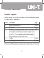
Model UT207/208
OPERATING MANUAL
Model UT207/208: OPERATING MANUAL
Table of Contents
Title
Page
Overview
Unpacking Inspection
Safety Information
Rules For Safe Operation
International Electrical Symbols
The Meter Structure
Functional Buttons
The Effectiveness of Functional Buttons
Display Symbols
Measurement Operation
A. DC/AC Voltage Measurement
B. Measuring Resistance
C. Testing Diodes
D. Testing for Continuity
E. Frequency Measurement
F. Duty Cycle Measurement
4
5
6
7
10
11
12
14
15
18
18
20
22
24
26
28
1
Model UT207/208: OPERATING MANUAL
Title
G. DC Current Measurement
H. AC Current Measurement
I. UT208 only: Temperature Measurement
Sleep Mode
Specifications
A. General Specifications
B. Environmental Requirements
Accuracy Specifications
A. DC Voltage
B. AC Voltage
C. Resistance
D. Diode Test
E. Continuity Test
F. Frequency
G. Duty Cycle
H. DC Current
2
Page
30
32
35
37
38
38
39
40
40
41
42
42
43
44
45
45
Model UT207/208: OPERATING MANUAL
Title
Page
47
48
49
49
50
I. AC Current
J. Temperature (UT208 only)
Maintenance
A. General Service
B. Replacing the Battery
3
Model UT207/208: OPERATING MANUAL
Overview
This Operating Manual covers information on safety and cautions. Please read the
relevant information carefully and observe all the Warnings and Notes strictly.
Warning
To avoid electric shock or personal injury, read the “Safety Information” and
“Rules for Safe Operation” carefully before using the Meter.
Digital Clamp Multimeter Model UT207/UT208 (hereafter referred to as “the Meter”)
are 3 5/6 digits with steady operations, fashionable structure and highly reliable
measuring instrument. The Meter uses large scale of integrated circuit with double
integrated A/D converter as its core and has full range overload protection.
The Meter can measure AC/DC Voltage, AC/DC Current, Frequency, Duty Cycle,
Resistance, Diodes, Continuity, Surge Current and etc.
UT208 has an extra temperature feature.
4
Model UT207/208: OPERATING MANUAL
Unpacking Inspection
Open the package case and take out the Meter. Check the following items carefully
to see any missing or damaged part:
Item
Description
Qty
1
2
3
English Operating Manual
Test Lead
Point Contact Temperature Probe (Only UT208) (This
included point contact temperature probe can only be used
1 piece
1 pair
1 pair
4
5
up to 230 . For any measurement is higher than that, the
rod type temperature probe must be used)
Tool box
9V Battery (NEDA1604A or 6LF22)
1 piece
1 piece
In the event you find any missing or damage, please contact your dealer immediately.
5
Model UT207/208: OPERATING MANUAL
Safety Information
This Meter complies with the standards IEC61010-1; IEC61010-2-032: in pollution
degree 2, overvoltage category (CAT. II 600V, CAT. III 300V) and double insulation.
CAT. II: Local level, appliance, PORTABLE EQUIPMENT etc., with smaller transient
overvoltages than CAT. III.
CAT. III: Distribution level, fixed installation, with smaller transient overvoltages than
CAT. IV
Use the Meter only as specified in this operating manual, otherwise the protection
provided by the Meter may be impaired.
In this manual, a Warning identifies conditions and actions that pose hazards to the
user, or may damage the Meter or the equipment under test.
A Note identifies the information that user should pay attention to.
International electrical symbols used on the Meter and in this Operating Manual are
explained on page 10.
6
Model UT207/208: OPERATING MANUAL
Rules For Safe Operation
Warning
To avoid possible electric shock or personal injury, and to avoid possible
damage to the Meter or to the equipment under test, adhere to the following
rules:
Before using the Meter inspect the case. Do not use the Meter if it is
damaged or the case (or part of the case) is removed. Look for cracks or
missing plastic. Pay attention to the insulation around the connectors.
Inspect the test leads for damaged insulation or exposed metal. Check the
test leads for continuity. Replace damaged test leads with identical model
number or electrical specifications before using the Meter.
Do not apply more that the rated voltage, as marked on the Meter , between
the terminals or between any terminal and grounding. If the value to be
measured is unknown, use the maximum measurement position and reduce
the range step by step until a satisfactory reading is obtained.
When measurement has been completed, disconnect the connection between
the test leads and the circuit under test, remove the testing leads awayl
7
Model UT207/208: OPERATING MANUAL
from the input terminals of the Meter and turn the Meter power off.
The rotary switch should be placed in the right position and no any
changeover of range shall be made during measurement is conducted to
prevent damage of the Meter.
Do not carry out the measurement when the Meter’s back case and battery
compartment are not closed to avoid electric shock.
Do not input higher than 600V between the two Meter’s input terminal to
avoid electric shock and damages to the Meter.
When the Meter working at an effective voltage over 70V in DC or 33V rms
in AC, special care should be taken for there is danger of electric shock.
Use the proper terminals, function, and range for your measurements.
Do not use or store the Meter in an environment of high temperature,
humidity, explosive, inflammable and strong magnetic field. The performance
of the Meter may deteriorate after dampened.
When using the test leads, keep your fingers behind the finger guards.
To avoid electric shock, do not touch the bare wires, connectors, unused
input terminals or the circuit under testing during measurement.
Disconnect circuit power and discharge all high-voltage capacitors before
testing resistance, continuity and diode.
8
Model UT207/208: OPERATING MANUAL
Replace the battery as soon as the battery indicator
appears. With a
low battery, the Meter might produce false readings that can lead to electric
shock and personal injury.
When servicing the Meter, use only the same model number or identical
electrical specifications replacement parts.
The internal circuit of the Meter shall not be altered at will to avoid damage
of the Meter and any accident.
Soft cloth and mild detergent should be used to clean the surface of the
Meter when servicing. No abrasive and solvent should be used to prevent
the surface of the Meter from corrosion, damage and accident.
The Meter is suitable for indoor use.
Turn the Meter off when it is not in use and take out the battery when not
using for a long time.
Constantly check the battery as it may leak when it has been using for
some time, replace the battery as soon as leaking appears. A leaking battery
will damage the Meter.
9
Model UT207/208: OPERATING MANUAL
International Electrical Symbols
AC (Alternating Current)
DC (Direct Current)
AC or DC
Grounding
Double Insulated
Warning. Refer to the Operating Manual
Deficiency of Built-In Battery
Continuity Test
Diode
Danger of High Voltage
Conforms to Standards of European Union
10
Model UT207/208: OPERATING MANUAL
The Meter Structure (see figure 1)
1. Hand Guards: to protect user’s hand
from touching the dangerous area.
2. Trigger: press the lever to open the
transformer jaws. When the pressure
on the lever is released, the jaws will
close.
3. Functional Buttons
4. Input Terminals
5. LCD Display
6. Rotary Switch
7. Transformer Jaw: designed to pick up
the AC and DC current flowing through
the conductor. It could transfer current
to voltage. The tested conductor must
vertically go through the Jaw center.
Figure 1
11
Model UT207/208: OPERATING MANUAL
Functional Buttons
Below table indicated for information about the functional button operations.
Button
Operation Performed
SELECT
Press SELECT button to select the alternate functions including
(UT208 only).
V ,
, %Hz, A and
Starts recording of maximum and minimum values.
Press to step the display through high (MAX) and low (MIN) readings
at any mode.
Press and hold for one second to exit MAX/MIN mode.
Press again to turn the display backlight off, otherwise it will
automatically off after 1 minute.
MAX/MIN
HOLD
Press HOLD to enter the Hold mode in any mode, the Meter
beeps.
Press HOLD again to exit the Hold mode to return to measurement
mode, the Meter beeps.
Turn the rotary switch or press SELECT button can also exit
Hold mode.
12
Model UT207/208: OPERATING MANUAL
Button
Operation Performed
HOLD
Press HOLD button for 2 seconds when turning on the Meter to
display full icon.
When the Meter is at %Hz, V
and A , press Hz to measure
frequency and duty cycle.
Hz
ZERO
Press ZERO to zeroing the display before measuring DC current.
13
Model UT207/208: OPERATING MANUAL
The Effectiveness of Functional Buttons
Not every functional buttons can be used on every rotary switch positions. Below
table describe which functional buttons can be used on which rotary switch positions
Rotary Switch
SELECT
Positions
Functional Buttons
MAX/MIN
HOLD
Hz
N/A
V
N/A
%Hz
N/A
N/A
N/A
66A
N/A
N/A
1000A
N/A
N/A
N/A
66A
1000A
o
ZERO
o
N/A
C F
14
N/A
N/A
Model UT207/208: OPERATING MANUAL
Display Symbols (see figure 2)
Figure 2
15
Model UT207/208: OPERATING MANUAL
Number
Symbol
Meaning
1
2
3
4
5
6
INRUSH
MIN
MAX
ZERO
H
AUTO
7
8
9
10
11
RMS
AC
Indicator for Surge current
Minimum reading displayed
Maximum reading displayed
Indicator for zeroing
Data hold is active
The Meter is in the auto range mode in which the
Meter automatically selects the range with the best
resolution.
True RMS indicator
Indicator for AC voltage or current
Indicates negative reading
Indicator for DC voltage
The battery is low.
Warning: To avoid false readings, which
could lead to possible electric shock or
personal injury, replace the battery as soon as
the battery indicator appears.
DC
16
Model UT207/208: OPERATING MANUAL
Number
Symbol
12
13
14
15
,K ,M
16
Hz, kHz, MHz
17
mV, V
18
19
A
20
21
%
Meaning
Sleep mode is on
Test of diode
The continuity buzzer is on
: Ohm. The unit of resistance.
k :Kilohm. 1x10³ or 1000 ohms
M :Megohm. 1x10⁶ or 1,000,000 ohms
Hz: Hertz. The unit of frequency.
KHz: Kilohertz. 1x10³ or 1000 hertz.
MHz: Meghertz. 1x10⁶ or1,000,000 hertz.
Volts. The unit of voltage.
mV: Millivolt. 1x10⁻³ or 0.001 volts
Amperes (amps). The unit of current.
The unit of temperature:
: Centigrade temperature
The unit of temperature:
: Fahrenheit temperature
Duty cycle measurement
17
Model UT207/208: OPERATING MANUAL
Measurement Operation
A. DC/AC Voltage Measurement (see figure 3)
Warning
To avoid harms to you or damages to the Meter from eletric shock, do not
attempt to measure voltages higher than 600V AC/DC, although readings may
be obtained.
Red
Red
Black
Figure 3
18
Black
Model UT207/208: OPERATING MANUAL
The DC Voltage ranges are: 6.6V, 66V and 600V
The AC Voltage ranges are: 6.6V, 66V and 600V
To measure DC/AC voltages, connect the Meter as follows:
1. Insert the red test lead into the V Hz terminal and black test lead into the COM
terminal.
2. Set the rotary switch to V . DC mesaurement mode and auto ranging is a
default. Press SELECT to switch to AC measurement mode.
3. Press Hz button to measure frequency or duty cycle, but the frequency or duty
cycle readings obtained from this range is only for reference.
4. Connect the test leads across with the object being measured.
The measured value shows on the display.
Note
When DC/AC voltage measurement has been completed, disconnect the connection
between the testing leads and the circuit under test and remove testing leads
from the input terminals.
19
Model UT207/208: OPERATING MANUAL
B. Measuring Resistance (see figure 4)
Warning
To avoid damages to the Meter or to the devices
under test, disconnect circuit power and
discharge all the high-voltage capacitors before
measuring resistance.
The resistance ranges are:
660 , 6.6k , 66k , 660k , 6.6M
and 66M
To measure resistance, connect the Meter as
follows:
Insert the red test lead into the V Hz terminal
1. and black test lead into the COM terminal.
Set the rotary switch to
. Resistance
2. measurement is a default or press SELECT
to switch to measurement mode.
20
Red
Figure 4
Black
Model UT207/208: OPERATING MANUAL
3. Connect the test leads across with the object being measured.
The measured value shows on the display.
Note
To obtain a more precise reading, you could remove the objects being tested from
the circuit when measuring.
When resistance measurement has been completed, disconnect the connection
between the testing leads and the circuit under test and remove testing leads
from the input terminals.
21
Model UT207/208: OPERATING MANUAL
C. Testing Diodes (see figure 5)
Warning
To avoid damages to the Meter or to the devices
under test, disconnect circuit power and
discharge all the high-voltage capacitors before
testing diodes.
Use the diode test to check diodes, transistors, and
other semiconductor devices. The diode test sends
a current through the semicondutor junction, then
measure the voltage drop across the junction. A
good silicon junction drops between 0.5V and 0.8V.
Red
To test the diode out of a circuit, connect the Meter
as follows:
Figure 5
22
Black
Model UT207/208: OPERATING MANUAL
1. Insert the red test lead into the V Hz terminal and black test lead into the COM
terminal.
2. Set the rotary switch to
. Press SELECT to switch to
measurement
mode.
3. For forward voltage drop readings on any semiconductor component, place the
red test lead on the component’s anode and place the black test lead on the
component’s cathode.
Note
To obtain a more precise reading, you could remove the objects being tested from
the circuit when measuring.
When diode testing has been completed, disconnect the connection between the
testing leads and the circuit under test and remove testing leads from the input
terminals.
23
Model UT207/208: OPERATING MANUAL
D. Testing for Continuity (see figure 6)
Warning
To avoid damages to the Meter or to the devices
under test, disconnect circuit power and
discharge all the high-voltage capacitors before
measuring continuity.
To test for continuity, connect the Meter as follows:
1. Insert the red test lead into the V Hz terminal
and the black test lead into the COM terminal.
2. Set the rotary switch to
and press
SELECT button to select measurement mode.
3. The buzzer sounds if the resistance of a circuit
under test is less than 30 .
4. The buzzer may or may not sound if the
resistance of a circuit under test is between 30
to 100 .
5. The buzzer does not sound if the resistance of
24
Red
Figure 6
Black
Model UT207/208: OPERATING MANUAL
a circuit under test is higher than 100 .
Note
When continuity testing has been completed, disconnect the connection between
the testing leads and the circuit under test and remove testing leads from the
input terminals.
25
Model UT207/208: OPERATING MANUAL
E. Frequency Measurement (see figure 7)
Warning
To avoid harms to you or damages to the Meter
from eletric shock, do not attempt to measure
voltages higher than 600V AC/DC, although
readings may be obtained.
The frequency ranges are:
660Hz, 6.6kHz, 66kHz, 660kHz, 6.6MHz and 66MHz.
To measure frequency, connect the Meter as follows:
Red
1. Insert the red test lead into the V Hz terminal
and the black test lead into the COM terminal.
2. Set the rotary switch to %Hz. Frequency
measurement mode is a default or press SELECT
to switch to Hz measurement mode.
3. Connect the test leads across with the object
26
Figure 7
Black
Model UT207/208: OPERATING MANUAL
being measured.
The measured value shows on the display.
Note
When frequency measurement has been completed, disconnect the connection
between the testing leads and the circuit under test, and remove the testing leads
away from the input terminals of the Meter.
27
Model UT207/208: OPERATING MANUAL
F. Duty Cycle Measurement (see figure 8)
Warning
To avoid harms to you or damages to the Meter
from eletric shock, do not attempt to measure
voltages higher than 600V AC/DC, although
readings may be obtained.
The duty cycle range is: 0.1%~99.9%.
To measure duty cycle, connect the Meter as follows:
1. Insert the red test lead into the V Hz terminal
and the black test lead into the COM terminal.
2. Set the rotary switch to %Hz. Press SELECT to
switch to % measurement mode.
3. Connect the test leads across with the object
being measured.
The measured value shows on the display.
28
Red
Figure 8
Black
Model UT207/208: OPERATING MANUAL
Note
When duty cycle measurement has been completed, disconnect the connection
between the testing leads and the circuit under test, and remove the testing leads
away from the input terminals of the Meter.
29
Model UT207/208: OPERATING MANUAL
G. DC Current Measurement (see figure 9)
The measurement ranges of current are: 66A
and 1000A .
To measure current, do the following:
1. Set the rotary switch to 66A
or 1000A .
2. Hold the Meter tight, don’t release. The Hall
components are very senstive not only to the
magnet but also to heat and machines reaction
force. Any shock will cause the changing in
reading in the short time.
3. Press the lever to open the transformer jaw.
4. Center the conductor within the transformer jaw,
then release the Meter slowly until the trasnformer
jaw is completely closed, Make sure the
conductor to be tested is placed at the center of
the transformer jaw, otherwise it will casue
deviation. The Meter can only measure one
30
Figure 9
Model UT207/208: OPERATING MANUAL
conductor at a time, to meausre more than one condutor at a time will cause deviation.
Note
If the Meter does not display 00.00 when it is at 66A
range, press ZERO to
zeroing. After zeroing, it allows 10 digits bouncing reading.
When the Meter is at 1000A , it displays 0 and it is not allowed to press ZERO
to zeroing.
When current measurement has been completed, disconnect the connection
between the conductor under test and the jaw, and remove the conductor away
from the transformer jaw of the Meter.
31
Model UT207/208: OPERATING MANUAL
H. AC Current Measurement (see figure 10)
Warning
The measurement ranges of current are: 66.00A
and 1000A .
To measure AC current, do the following:
1. Set the rotary switch to 66A
or 1000A .
2. Hold the Meter tight, don’t release. The Hall
components are very senstive not only to the
magnet but also to heat and machines reaction
force. Any shock will cause the changing in
reading in the short time.
3. Press the lever to open the transformer jaw.
4. Center the conductor within the transformer jaw,
then release the Meter slowly until the trasnformer
jaw is completely closed, Make sure the
conductor to be tested is placed at the center of
the
32
Figure 10
Model UT207/208: OPERATING MANUAL
transformer jaw, otherwise it will casue deviation. The Meter can only measure
one conductor at a time, to meausre more than one condutor at a time will cause
deviation.
5. When the measuring current >1A, press Hz button to step through AC current,
frequency and duty cycle measurement mode. But the frequency or duty cycle
readings obtained from this range is only for reference.
6. Press SELECT to carry out surge current measurement.
To measure surge current Measurement, do the following:
1. Set the rotary switch to 1000A .
2. Press SELECT when the Meter displays the minimum readings. The Meter then
displays “-----’’ means it is ready to carry out surge current measurement.
3. Turn on the electrical equipments at that time to measure the moment start up
current.
4. Press and hold SELECT for one second to exit surge current measurement mode.
5. When the Meter is at surge current measurement, it is locked to the highest
measurement range.
33
Model UT207/208: OPERATING MANUAL
Note
When current measurement has been completed, disconnect the connection
between the conductor under test and the jaw, and remove the conductor away
from the transformer jaw of the Meter.
34
Model UT207/208: OPERATING MANUAL
I. UT208 only: Temperature Measurement (see figure 11)
The temperature measurement range: -40 ~1000
and -40 ~1832 .
To measure temperature measurement, connect the
Meter as follows:
1. Insert the red temperature probe into the V Hz
terminal and the black temperature probe into
the COM terminal.
2. Set the rotary switch to
. Press SELECT to
switch between
and measurement mode.
3. Place the temperature probe to the object being
measured.
The measured value shows on the display.
Figure 11
35
Model UT207/208: OPERATING MANUAL
Note
When the Meter is at
range, it beeps to remind user to insert temperature
probe.
The Meter automatically displays the room temperature when the temperature
probe is inserted but without any input.
The included point contact temperature probe can only be used up to 230 .
For any measurement is higher than that, the rod type temperature probe must
be used.
When the temperature measurement has been completed, disconnect the
connection between the temperature probe and the object under test, and remove
the temperature probe away from the input terminals of the Meter.
36
Model UT207/208: OPERATING MANUAL
Sleep Mode
To preserve battery life, the Meter automatically turns off if you do not turn the rotary
switch or press any button for around 15 minutes.
The Meter beeps 3 times in one minute before entering Sleep Mode and long beep
one time just before entering Sleep Mode.
The Meter can be activated by turning the rotary switch or pressing the button based
on ‘‘The Effectiveness of Functional Buttons’’ on page 14
If the Meter is activated by pressing button, the Meter will keep the measurement
value before entering Sleep Mode.
Press MAX/MIN, LIGHT or
feature.
Hz to turn on the Meter can disable the Sleep Mode
37
Model UT207/208: OPERATING MANUAL
Specifications
A. General Specifications:
Maximum Voltage between any Terminals and grounding: Refer to different range
input protection voltage.
Display: 3 5/6 digits LCD display, Maximum display 6666.
Polarity: Auto
Overloading: Display OL or –OL.
Battery Deficiency: Display
.
Sampling: 3 times per second.
Measurement Deviation: The conductor being meaured is not placed in the center
of the jaw during AC/DC current measurement, it will cause extra 1% deviation
based on the stated accuracy.
Drop Test: 1 meter drop test passed.
Max. Jaw Size: 55mm diameter.
Projected Max. Current conductor size: 45mm diameter.
Electro-Magnetic: When carrying out measurement near the electro-magnetic, it
may cause unstable or wrong reading.
Power: 1 x 9V battery (6LF22 1604A)
38
Model UT207/208: OPERATING MANUAL
Battery Life: typically 150 hours (alkaline battery)
Dimensions: 285.3mm x 105mm x 44.5mm
Weight: Approximate 533g (battery included)
B. Environmental Requirements
The Meter is suitable for indoor use.
Altitude: Operating: 2000m
Storage: 10000m
Safety/ Compliances: IEC61010-1; IEC61010-2-032. CAT.II 600V, CAT.III 300V
over voltage and double insulation standard, pollution degree 2.
Temperature and humidity:
Operating:
0 ~30 ( 80%R.H)
30 ~40 ( 75%R.H)
40 ~50 ( 45%R.H)
Storage:
-20 ~+60 ( 80%R.H)
39
Model UT207/208: OPERATING MANUAL
Accurate Specifications
Accuracy: (a% reading + b digits), guarantee for 1 year.
Operating temperature: 23
5
Relative humidity: 80%R.H
Temperature coefficient: 0.1x(specified accuracy)/1
A. DC Voltage
Range
6.600V
66.00V
600.0V
Resolution
1mV
10mV
100mV
Accuracy
(0.8%+1)
Remark: Input Impedance: 10MΩ
40
Overload protection
600V DC/AC
Model UT207/208: OPERATING MANUAL
B. AC Voltage
Range
6.600V
66.00V
600.0V
Resolution
1mV
10mV
100mV
Accuracy
(1.2%+5)
Overload protection
600V DC/AC
Remarks:
Input Impedance: 10M
Frequency Response: 40Hz~400Hz
Change to AC:
Combine AC and True RMS response method. Input sine wave to adjust. Non
sine wave must follow the below data to adjust:
Peak factor: 1.4~2.0, add 1.0% on the stated accuracy
Peak factor: 2.0~2.5, add 2.5% on the stated accuracy
Peak factor: 2.5~3.0, add 4.0% on the stated accuracy.
41
Model UT207/208: OPERATING MANUAL
C. Resistance
Range
660.0Ω
6.600kΩ
66.00kΩ
660.0kΩ
6.600MΩ
66.00MΩ
Resolution
0.1Ω
1Ω
10Ω
100Ω
1kΩ
10kΩ
Accuracy
(1.2%+2)
(1%+2)
Overload protection
250VAC
(1.2%+2)
(1.5%+2)
D. Diode Test
Range
Resolution
1mV
Accuracy
0.5V~0.8V (Open
circuit voltage
approx. 3.0V)
42
Overload protection
250VAC
Model UT207/208: OPERATING MANUAL
E. Continuity Test
Range
Resolution
0.1
Accuracy
Around 30Ω,the
buzzer beeps.
(Open circuit voltage
approx. –1.2V)
Overload protection
250VAC
Remark:
The buzzer may or may not beeps when the resistance of a circuit under test is
between 30Ω~100Ω.
The buzzer does not beep when the resistance of a circuit under test is > 100Ω
43
Model UT207/208: OPERATING MANUAL
F. Frequency
Range
660.0Hz
6.600kHz
66.00kHz
660.0kHz
6.600MHz
66.00MHz
Resolution
0.1Hz
0.001kHz
0.01kHz
0.1kHz
0.001MHz
0.01MHz
Accuracy
(0.1%+3)
Remarks:
Input Sensitivity (a) as follows:
When a 10Hz: the Meter does not response
When 10Hz < a 100kHz: 300mV rms
When a >100kHz: 600mV rms
44
Overload protection
250VAC
Model UT207/208: OPERATING MANUAL
G. Duty Cycle
Range
0.1%~99.9%
Resolution
0.1%
Accuracy
For reference only
Overload protection
250VAC
H. DC Current
Range
66.00A
1000A
Resolution
0.01A
1A
Accuracy
(2%+40)
(2%+8)
Overload protection
250VAC
Warning
The operating temperature must be 0
~ 40
45
when measuring current.
Model UT207/208: OPERATING MANUAL
Remarks:
If the reading is positive, the current direction is from bottom to up. See figure
10, the front case face up while the bottom case face down. Hold the Meter tight,
do not release. The Hall components are very sensitive not only to the magnet
but also to heat and machines reaction force. Any shock will cause the changing
in reading in the short time. Follow the below procedure to measure current will
be more precise:
1. Turn off the current of tested conductor.
2. Hold the Meter tight and press the lever to open the transformer jaw. Center
the conductor within the transformer jaws, then release the Meter slowly until
the transformer jaw is completely closed. Make sure the conductor to be tested
is placed at the center of the transformer jaw, otherwise it will cause +1.0%
deviation based on the stated accuracy.
3. Press ZERO button to display zero.
4. Turn on the current of tested conductor reading the stable value of clamp
meter.
5. The obtained reading will be more precise.
46
Model UT207/208: OPERATING MANUAL
I. AC Current
Range
Resolution
66.00A
1000A
0.01A
1A
Accuracy
Frequency
Response
50Hz ~ 60Hz
(2%+40)
(2%+8)
Overload protection
250VAC
Warning
The operating temperature must be 0
~40
when measuring current.
Remarks:
It may have unstable or wrong sensed readings, it will not affect measurement
result.
Hold the Meter tight, do now release. The Hall components are very sensitive
not only to the magnet but also to heat and machines reaction force. Any shock
will cause the changing in reading in the short time.
Change to AC:
Combine AC and True RMS response method. Input sine wave to adjust.
47
Model UT207/208: OPERATING MANUAL
Non sine wave must follow the below data to adjust:
Peak factor: 1.4~2.0, add 1.0% on the stated accuracy.
Peak factor: 2.0~2.5, add 2.5% on the stated accuracy
Peak factor: 2.5~3.0, add 4.0% on the stated accuracy.
J. Temperature (UT208 only)
Range
Resolution
40 ~1000
1
-40 ~1832
1
Accuracy
-40 ~0 : (3%+4)
0 ~400 : (1%+3)
400 ~1000 :
(2%+10)
Overload protection
-40 ~32 : (3%+8)
250VAC
32 ~752 : (1%+6)
752 ~1832 :
(2%+18)
48
Model UT207/208: OPERATING MANUAL
MAINTENANCE
This section provides basic maintenance information including battery replacement
instruction.
Warning
Do not attempt to repair or service your Meter unless you are qualified to do
so and have the relevant calibration, performance test, and service information.
To avoid electrical shock or damage to the Meter, do not get water inside the
case.
A. General Service
Periodically wipe the case with a damp cloth and mild detergent. Do not use
abrasives or solvents.
To clean the terminals with cotton bar with detergent, as dirt or moisture in the
terminals can affect readings.
Turn the Meter power off when it is not in use.
Take out the battery when it is not using for a long time.
Do not use or store the Meter in a place of humidity, high temperature, explosive,
inflammable and strong magnetic field.
49
Model UT207/208: OPERATING MANUAL
B. Replacing the Battery (see figure 12)
Warning
To avoid false readings, which could lead
to possible electric shock or personal
injury, replace the battery as soon as the
battery indicator “ ” appears.
Make sure the transformer jaw and the
tets leads are disconected from the circuit
being tested before opening the case
bottom.
Figure 12
50
Model UT207/208: OPERATING MANUAL
To replace the battery:
1. Turn the Meter off and remove all the connections from the input terminals
2. Turn the Meter’s front case down.
3. Remove the screw from the battery compartment, and separate the battery
compartment from the case bottom.
4. Take out the old battery and replace with a new 9V battery (6LF22, 1604A).
5. Rejoin the case bottom and the battery compartment, and reinstall the screw.
51
Model UT207/208: OPERATING MANUAL
* END *
This operating manual is subject to change without notice.
52
Model UT207/208: OPERATING MANUAL
Copyright 2007 Uni-Trend Group Limited.
All rights reserved.
Manufacturer:
Uni-Trend Technology (Dongguan) Limited
Dong Fang Da Dao
Bei Shan Dong Fang Industrial Development District
Hu Men Town, Dongguan City Guang Dong Province
China
Postal Code: 523 925
Headquarters:
Uni-Trend Group Limited
Rm901, 9/F, Nanyang Plaza
57 Hung To Road Kwun Tong Kowloon, Hong Kong
Tel: (852) 2950 9168
Fax: (852) 2950 9303
Email: [email protected]
http://www.uni-trend.com
53