1
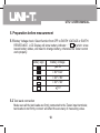
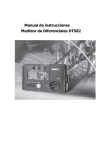
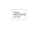
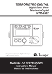
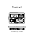
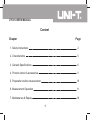
UT521 USERS MANUAL
Content
Chapter
Page
1. Safety Instructions
2
2. Characteristics
5
3. General Specifications
6
4. Product outlook & accessories
9
5. Preparation before measurement
10
6. Measurement Operation
11
7. Maintenance & Repair
18
1
UT521 USERS MANUAL
1.Safety Instructions
This operation manual includes the user guidance and safety instruction when using
the tester, please read it before using.
Before using the Tester, please read and understand the operating manual
including the content.
Keep the operating manual properly, and let it easy to get it for reference during
the process of testing.
When using the Tester, user must follow the testing procedure as mentioned in
the operating manual.
Careful reading the operating manual regarding the safety information and it is
content.
Must be followed all the related safety instructions, otherwise it may cause
accidents or damage the Tester.
2
UT521 USERS MANUAL
Safety sign "
"has 3 meaning in this manual, user has to pay attention to this
sign"
"for operation.
Danger
Warning
Caution
identifies conditions and actions that most likely pose hazard(s)
or die.
identifies conditions and actions that will pose hazard(s) or
die.
identifies conditions and actions that will pose hazard(s) or
damage the Tester.
Danger
Do not use the Tester around explosive environment, which may cause fire and
explosion.
Do not use the Tester in wet environment or do not make any connection work
when your fingers are wet.
Do not apply the load more than the Tester capacity or range.
Do not open battery compartment while testing.
3
UT521 USERS MANUAL
Warning
Do not use the Tester if it is damaged or metal part is exposed.
Do not disassemble the tester un-intentionally. If it needs repair, please contact
our after-sales services or our agents.
Do not change battery or open battery compartment when the Tester is wet. Soft
cloth should be used to dry it first, and then carry on.
Make sure the Tester is turned off when changing battery or opening the battery
compartment.
Caution
Ensure test lead probe insert into the corresponding port before measurement.
Take the battery out from the Tester if it is not used for a long time.
Do not expose the Tester in extreme temperature and wet environment.
Soft cloth and mild detergent should be used to clean the surface of the Tester
when servicing. No abrasive and solvent should be used
Dry the tester before storing if it is wet.
This Tester has the follow signs,please pay attention to the content when using:
identifies danger, warning, caution
identifies double or reinforced insulation
identifies AC[AC]
Grounding
Conforms to Standards of European Union
4
UT521 USERS MANUAL
2.Characteristics
The Tester is using micro controller with high accuracy and reliability; it can measure
every electric wire, electric installation, anti-thunder equipmentís earth resistance
value of those earth system. Also, it can carry earth voltage measurement. (Note:
the Tester should not be used outdoor hazard environment, like raining, thunder
etc.)
2.1
2.2
2.3
2.4
2.5
With backlight display and battery check function.
Data logging for 20 sets of data.
With auto switch-off save energy function.
Precision 3-Wires Testing and Simple 2-Wires Testing.
During earth voltage testing, if C port or E port don't contact properly, LCD display
will show"- - - - "indication.
2.6 Over-range Display"OL"indication.
2.7 Double insulation or reinforced insulation safety manufacturing.
5
UT521 USERS MANUAL
3.General Specifications
3.1 Operating temperature and Relative humidity(20
Range
Earth Voltage
Earth
Resistance
Measure Range
0V~200V(50/60Hz)
20
0.00 ~20.00
200
0.0
2000
0
~200.0
5 & 75%RH):
Best Accuracy
(1.0%+4)
(2.0%+10) (20
position)
(2.0%+3)(200
or 2000
position)
(Auxiliary earth resistance 500
~2000
(accuracy
5%);earth voltage 10Vac)
3.2 Application standard:
IEC 61010-1 CATIII 600V Polluting Grading: Grade II
IEC 61557-1,5
IEC 61010-2-31
6
UT521 USERS MANUAL
3.3 Measure methods:
(1) Earth Voltage Testing:average respond
(2) Earth Resistance Testing : testing signal frequency : around 820Hz,current :
20 position around 3.2mA
3.4 Maximum operating accuracy:
Maximum operating accuracy within measure range:( 30%)
20 : 5.00 ~20.00
200 : 20.0 ~200.0
2000 : 200 ~2000
3.5 Working condition:
Temperature:5 ~40
Relative humidity: 80%RH(no fog)
Height above Sea Level: 2000 meters
3.6 Storage condition:
Temperature:-20 ~60
Relative humidity: 75%RH(no fog)
7
UT521 USERS MANUAL
3.7 Power source:[1.5V Alkaline Battery (AA)*6]
3.8 Overload protection:
Earth Resistance:200 Vac (10 seconds)
Earth Voltage:400 Vac (30 seconds)
3.9 Insulation Resistance:The insulation impedance between measure circuit and
housing is not less than 20M
.
3.10 Product size:160mmx70.5mmx100mm.
3.11 Product Weight:around 560g.
3.12 Accessories:
Green test lead 5 meter
Yellow test lead 10 meter
Red test lead 20 meter
Auxiliary earth stakes
One plug test lead with alligator clip
1.5V Alkaline Battery (AA)
Carrying Bag
English manual
8
1 piece
1 piece
1 piece
2 pieces
1 set
6 pieces
1 set
1 piece
UT521 USERS MANUAL
4. Product outlook & accessories:(figure 1)
1
LCD Display
2
LIGHT/LOAD button
3
HOLD/SAVE button
4
TEST button
5
ON/OFF function
6
Input terminals
7
Standard 3-Wires test leads
8
Simple 2-Wires test leads
9
figure 1
9
Auxiliary earth stakes
UT521 USERS MANUAL
5. Preparation before measurement
5.1 Battery Voltage check: Select function from OFF to EARTH VOLTAGE or EARTH
RESISTANCE, LCD Display will show battery indicator : "
" which show
lowest battery status, and need to change battery, otherwise the Tester cannot
work properly.
Battery sign
Battery Voltage
8.2V
7.8V~8.2V
7.4V~7.8V
7.0V~7.4V
7V
5.2 Test leads connection
Make sure all the test leads are firmly connected to the Tester input terminals;
test leads do not firmly connect will affect the accuracy of measuring value.
10
UT521 USERS MANUAL
6. Measure method
Warning
When the Tester carry out earth resistance testing, the distance
between E and C have the maximum voltage around 50V volt.
Do not touch the external part of test leads and auxiliary earth
stake in order to avoid shock hazard.
6.1 Precision Measurement (using standard test leads for measurement):
a. place 2 ground stakes in earth/dirt. Minimum distance between earth electrode(E),
probe(P) and auxiliary earth (C) should be 5-10 meter apart, as below connection
figure 2:
(Attention:ensure the ground stakes in the moisture soil. If the soil is too dry, it
need to fill-in sufficient water. Rock or sand also needs moisture before testing.
If the testing site is inside the urban city with concrete cover which is hard to
put in the ground stakes, it can use 25cm X 25 cm two steel plates (or using
the existing ground stakes) place horizontally in concrete surface, and cover
by moisture towel with sufficient water, replace measurement earth, it still can
make measurement in general situation.)
11
UT521 USERS MANUAL
Red
Yellow
Green
m
Auxiliary
Earth Spikes
m
Earthed Electrode
Under Test
figure2
C: auxiliary electrode
P: potential electrode
12
E: earth electrode
UT521 USERS MANUAL
b. Earth Voltage Testing:Select function OFF to EARTH VOLTAGE, LCD display will
show voltage, connect test leads in V and E, then connect to the testing point,
LCD display will show earth voltage value (Attention:measure earth voltage does
not need to press TEST button). If the measuring value>10V, then it need to
switch-off all the related voltage equipment. Wait until the earth voltage decrease,
and then do it again. Otherwise, it will affect the accuracy of earth resistance.
Warning:
Earth voltage testing only work in V and E, C and P connecting cable must be
separated. Otherwise, it will cause danger and damage the Tester.
c. Earth Resistance Testing:Select function OFF to EARTH RESISTANCE 2000
(Maximum),press"TEST"button, LCD display will show earth resistance value. If
the resistance value <200 ,then select function from OFF to earth resistance
200 ,LCD display will show earth resistance value. If the resistance value
<20 ,then select function from OFF to earth resistance 20 ,LCD display will
show earth resistance value; Of course, you can follow the other selecting order
for testing. In summary, you need to select the best measurement position to
measure for getting the best accuracy.
13
UT521 USERS MANUAL
press"TEST"button, the button's light will be on, which shows the Tester is in
measurement.
(Note:when C or E does not connect properly, auxiliary earth resistance or earth
resistance excess the load (like 20 excess around 14K ),or testing terminal open
circuit,LCD display will show"- - - - ",then it need to double check the connection
parts, whether soil is too dry, whether auxiliary earth stakes is close to earth.)
When the earth resistance testing point over the selected measuring range,
meanwhile the selected 20 position less than around 14K , or 200
position less than around 26K , or 2000 position less than around 78K ,LCD
display will show "OL"(overload). Warning:If the auxiliary earth stake is banning
or touch the other materials, it will affect the reading. When connect the test leads,
it must clean the auxiliary earth stake. If the auxiliary earth stake value is too large,
it also cause the deviation in reading.
d. The tester should be switch - on when press the button and select the function
key.Auto switch off after around 10 minutes for power save(except earth resistance
testing function on).
e. Backlight on:while testing in poorly lighted area, it needs backlight press
"Light/Load"button,backlight function will be on and LCD display the corresponding
sign. Press"Light/Load"button again, then it will switch-off backlight function.
14
UT521 USERS MANUAL
f. Hold function:while testing, press slightly"Hold/Save"button,save data function
will be on, the corresponding testing value will be saved and LCD display the
corresponding sign. Press slightly"Hold/Save"button again, then it will cancel this
function.
g. Storage function:
1.storage data press"Hold/Save"button for around 2 seconds. Storage function
will be on and save the corresponding data. Press "Hold/Save"button once again
to save the 2nddata; press"Hold/Save"button again to save the 3rd data...,For
switch-off this function, press"Hold/Save"button for around 2 seconds.
2.Read data press"Light/Load"button for around 2 seconds, it will show address
serial number 01 saved data. Press"Light/Load"button once again to show the
address serial number 02 saved data...until the 20th saved data. If you want to
return back the previous saved data, press "Hold/ Save"once; (In the situation"Hold/
Save"button"Light/Load"button (slightly press) is working like up and down button).
For switch-off this function, press"Light/Load"button for around 2 seconds.
3. Clear saved data
press"Hold/Save"button and "Light/Load"button simultaneously, then switch-on
the Tester, LCD display will show"C L .",
Meanwhile, all the data in the storage will be deleted(20 sets of data or part of
data can be deleted).
15
UT521 USERS MANUAL
6.2 Simple measurement(use simple 2-Wires test leads for measurement):
This method will be used when the auxiliary earth stake cannot be used. Use
the expose earth resistance object from the ground as earth, like metal water
bath, water pile, wire ground, building earth, also can use 2-wires test leads
method (E and P&C terminals).Connection as figure 3:
Supply Transformer
Primary
Side
Red
Secondary
Side
Green
r
Reference Earthed
Electrode
Earthed Electrode
Under Test
figure 3
16
UT521 USERS MANUAL
When using this method, P and C have already connected together.
Danger
When using commercial electricity power systemís grounding point as a
reference testing point, please be careful for voltage pose a shock hazard
17
UT521 USERS MANUAL
7. Maintenance & Repair
7.1 Maintenance
7.1.1 Replacing battery and repair(please see figure 4) After low battery indicator
show, replacing battery immediately as follows:
figure 4
18
UT521 USERS MANUAL
a. switch-off the Tester and remove all the test leads.
b. release the screw in bottom part,and open battery compartment.
c. Replacing all old battery (6) with new battery.
d. After replacing the battery, rejoin the battery compartment and firmly screw.
Remove all the batteries if the Tester do not use for a long time, so that it
avoid the leakage and corrosion in the battery compartment.
7.1.2 Cleaning the Tester
Soft cloth and mild detergent should be used to clean the surface of the Tester,
because solvent will corrosive the display.
7.1.3 Must be avoiding moisture.
7.2 Repair
7.2.1 Contact our after-sales service department or agents when the following thing
happens:
a. The Tester is being damage.
b. LCD display abnormal.
c. Unreasonable deviation when in normal use.
d. Buttons do not function properly and confusion.
7.2.2 when the Tester needs repair, please bring it to the professional technician or
authorized repair department for repair.
**END**
19
UT521 USERS MANUAL
This operating manual is subject to change without notice.
20
UT521 USERS MANUAL
21