1
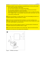
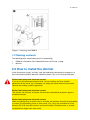
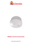
EM6610 e-Domotica Flush-Mounted Universal
Dimmer 1-gang
2 | ENGLISH
EM6610 e-Domotica Flush-Mounted Universal
Dimmer 1-gang
Table of contents
1.0 Introduction................................................................................................................. 2
1.1 Functions and features .......................................................................................... 2
1.2 Packing contents.................................................................................................... 4
2.0 How to install the dimmer........................................................................................... 4
3.0 How to put the dimmer into operation ....................................................................... 5
3.1 Add the switch to an e-Domotica e-Centre ........................................................... 5
4.0 How to operate the dimmer ....................................................................................... 6
5.0 What should I do if there is a problem?..................................................................... 6
5.1 Resetting the dimmer to the factory settings (Reset) ........................................... 7
6.0 Z-wave Commands .................................................................................................... 7
7.0 Frequently Asked Questions...................................................................................... 7
8.0 Service and support ................................................................................................... 7
9.0 Warning and points of attention ................................................................................. 8
10.0 Warranty conditions ................................................................................................. 9
11.0 Declaration of Conformity ........................................................................................ 9
1.0 Introduction
Congratulations with the purchase of this high-quality Eminent e-Domotica product!
This product has undergone extensive testing by Eminent’s technical experts. Should
you experience any problems with this product, you are covered by a five-year
Eminent warranty. Please keep this manual and the receipt in a safe place.
1.1 Functions and features
The EM6610 Flush-Mounted Universal Dimmer 1-gang, will be referred to below as
"dimmer". The dimmer is used to switch and dim luminaires (see technical data) via Zwave using the e-Domotica e-Centre 2.
The dimmer automatically recognizes the connect load, is overload-proof, short-circuitproof and hum-free, and has a soft start function which slowly dims up a connected
load.
Caution: The dimmer requires a minimum load of 25 VA for operation. If this is not
met, the dimmer may be damaged.
Caution: Connected devices can be damaged if you connect mixed loads (inductive
and capacitive) at the same time.
3 | ENGLISH
Caution! If you operate devices that do not correspond to the technical specifications
(see technical data), you can damage the connected devices and the radio receiver.
•
Only connect luminaires to the dimmer.
•
Do not connect luminaires with energysaving lamp(s).
•
Do not connect combinations of electronic and conventional transformers
•
Only dimmable transformers may be connected.
•
Connecting combinations of transformers and ohmic loads, incandescent lamps,
230 V halogen lamps is only permitted if the power of the ohmic load is max. 30%
of the entire connected load.
Note: Do not use dimmers on socket-outlets! The risk of overloading and the risk of
unsuitable appliances being connected is too high.
Note: If the load on connected wound transformers is too low, the dimmer may
malfunction during operation. The load on the transformer should therefore be at least
40% of the nominal power of the transformer.
Note: An excessive load will trigger the dimmer's overload protection. Reduce the
connected load and then switch the dimmer on again.
Note: If you install several dimmers next to each other, reduce the maximum load
allowed by 20% because of the reduced heat dissipation.
Figure 1 – EM6610 connectors
4 | ENGLISH
Figure 2 – Mounting the EM6610
1.2 Packing contents
The following parts need to be present in the packing:
•
EM6610 e-Domotica Flush-Mounted Universal Dimmer 1-gang
•
Manual
2.0 How to install the dimmer
Install the dimmer simply "invisibly" near the load to be connected, for example in a
flush-mounted installation box with a blanking cover (Fig. 2) or ceiling junction box.
Risk of fatal injury from electrical current.
If you do not have enough electrical skills, do not continue and let a certified
electrician do the job for you. Otherwise you might get injured and/or electrocuted.
Observe the country specific regulations.
Risk of fatal injury from electrical current.
The dimmer has no basic insulation and must be installed with protection against
accidental contact.
Risk of fatal injury from electrical current.
When a blanking cover or other cover is installed, the distance from the fixing brackets
or screws (of the blanking cover or other cover, Fig. 2 A) to the connections of the
dimmer (Fig. 2 B) must be at least 4 mm once installed. Suitable covers or a lower
installation box might have to be used.
5 | ENGLISH
The fixing brackets or fixing screws of the blanking cover may also not press against
the housing; if necessary, change the mounting position of the dimmer accordingly.
Risk of fatal injury from electrical current.
The outputs may carry an electrical voltage even when the dimmer is switched off.
Always disconnect the fuse in the incoming circuit from the supply before working on
connected loads.
1.
2.
3.
Disconnect the circuit from the mains.
Connect the dimmer as shown (Fig. 1):
a. Neutral conductor at terminal "N" (A).
b. Phase at terminal "L" (B).
c. Luminaire at terminal "~" (C).
d. Extension push-button (optional) at terminal "1" (D).
Place the antenna as far as possible from metal parts (connecting cables,
retaining rings, etc.) to avoid interruptions to the Z-wave signal.
Metal surfaces in the immediate vicinity of the dimmer can affect reception. Therefore,
do not install the dimmer in a flush-mounted box made of metal.
3.0 How to put the dimmer into operation
After installation:
1. Switch on the mains voltage.
2. The connected luminaires flicker for around ten seconds and then switch off
again. The dimmer has detected the load and is ready for operation.
Note: The lights will flicker in this way (load detection) after every interruption in the
mains voltage.
3.1 Add the switch to an e-Domotica e-Centre
1.
2.
3.
4.
5.
6.
7.
Make sure your computer is completely started.
Open your computer’s web browser.
Enter “http://ecentre” in the address bar of your web browser and press the
‘Enter’ key on your keyboard.
The webpage of the e-Centre will be shown. If the Wizard is started, click ‘Exit
Wizard’ to go to the ‘e-Domotica Products’ page.
Click the ‘Include’ button. The e-Centre will start to search for new e-Domotica
devices.
Press the button on the dimmer three times within 1,5 seconds.
A message will appear: ‘Product found’.
If the device is not found, press the ‘Exclude’ button in the e-Centre’s webpage and
then click the button on your switch. After this procedure you can add the new device
correctly.
6 | ENGLISH
8.
9.
Give the connected and found device a name, choose a location and click ‘Save’.
The dimmer has now been added to the e-Centre. The e-Centre will now be able
to control the switch.
10. You can now put the dimmer into the junction box. We suggest to disable the
mains by turning off the main switch of the house when putting the dimmer in the
junction box.
4.0 How to operate the dimmer
You can operate the dimmer by means of the following operating elements:
•
EM6505 e-Domotica e-Centre
•
EM6625 e-Domotica Push-button
•
EM6511 e-Domotica Remote Control (using a scene)
•
Smart phone or tablet
Switching/dimming luminaires
•
Switching on/off: Press the button briefly. The luminaire is always switched on at
the level of brightness that was last set (memory function).
•
Dimming brighter/darker: Press on the device button on the e-Centre screen to
set the level of brightness.
If the dimmer is switched on, the LED lights up (Fig. 1F).
You can also operate the dimmer at the device via the switch button (Fig. 1E). Only
insulated tools may be used for this operation, e.g. an insulated phase tester.
5.0 What should I do if there is a problem?
The dimmer switches off regularly in the operating state or cannot be switched back
on.
•
The connected load is too great and the dimmer has overheated. Allow the
dimmer to cool down and reduce the connected load.
•
Rectify any possible short circuits. Then switch the dimmer on and wait until the
load detection has ended (light stops flickering).
The load cannot be operated by the e-Centre, push-button or remote control?
•
Make sure that the maximum range is not exceeded and that there are no metal
surfaces such as metal cabinets in the Z-wave transmission path. If you want to
check whether the problem is due to the transmission path, carry the transmitter
to the receiver and operate it there.
7 | ENGLISH
5.1 Resetting the dimmer to the factory settings (Reset)
Under certain circumstances, it may be necessary to reset the dimmer to factory
settings and to reconfigure:
1.
2.
Press the dimmer's switch button three times within approx. 1.5 seconds (with an
insulated tool such as an insulated phase tester; Fig.1E). The LED (Fig.1F) in the
dimmer blinks.
Then press and hold the switch button for approx. five seconds until the LED
goes out. The dimmer has been reset to its factory settings.
Caution! When you reset to the factory settings, all the settings and connections for
this device are deleted. The radio system may no longer work and will need to be
reconfigured.
6.0 Z-wave Commands
Inclusion:
Have your Z-wave Controller entered inclusion mode, press the On/off button of the
mini switch three times.
Exclusion:
Have your Z-wave Controller entered exclusion mode, press the On/off button of the
mini switch three times. Once the node has been excluded, the LED will go into an
interval of two seconds on and two seconds off.
Reset:
Press the On/Off button three times to enter inclusion mode. Within one second, press
On/Off button again until LED is off. The home ID and node ID will be cleared and
reset to factory default.
7.0 Frequently Asked Questions
The latest frequently asked questions for your product can be found on the support
page of your product. Eminent will update these pages frequently to assure you have
the most recent information. Visit www.e-domotica.com/support/faqs for more
information about your product.
8.0 Service and support
This users manual has been carefully written by Eminent’s technical experts. If you
have problems installing or using the product, please fill out the support form at the
website www.e-domotica.com/support/customer-service
You can also contact us by phone. Below you will find a list with phone numbers for
each supported country.
8 | ENGLISH
Country
Belgium (Dutch)
Belgium (French)
Denmark
Finland
Germany
Italy
Norway
Spain
Sweden
The Netherlands
UK
Phone number
070 277 286
070 277 286
+45 69918565
+35 8942415826
+49 (0)30 887 89 298
+39 0240042016
+47 21075033
807 080 042
+46 840 309985
0900-3646368
+44 (0)203 318 9998
Rate per minute*
€0.30
€0.30
Local costs
Local costs
Local costs
Local costs
Local costs
€0.41
Local costs
€0.45
Local costs
* Rates mentioned in this table do not include cell phone charges.
9.0 Warning and points of attention
Due to laws, directives and regulations set out by the European parliament, some
(wireless) devices could be subject to limitations concerning its use in certain
European member states. In certain European member states the use of such devices
could be prohibited. Contact your (local) government for more information about this
limitations.
Always follow up the instructions in the manual, especially where it concerns devices
which need to be assembled.
Warning: In most cases this concerns an electronic device. Wrong/improper use may
lead to (severe) injuries!
Repairing of the device should be done by qualified Eminent staff. The warranty
immediately voids when products have undergone self repair and/or by misuse. For
extended warranty conditions, please visit our website at:
www.e-domotica.com/support/warranty
*Tip: Eminent e-Domotica manuals are written with great care. However, due to new
technological developments it can happen that a printed manual does not longer
contain the most recent information.
If you are experiencing any problems with the printed manual or you can not find what
you are looking for, please always check our website www.e-domotica.com first for the
newest updated manual.
Also, you will find frequently asked questions in the FAQ section. It is highly
recommended to consult the FAQ section. Very often the answer to your questions will
be found here.
9 | ENGLISH
10.0 Warranty conditions
The five-year Eminent warranty applies to all Eminent e-Domotica products unless
mentioned otherwise before or during the moment of purchase. When having bought a
secondhand Eminent e-Domotica product the remaining period of warranty is
measured from the moment of purchase by the product’s first owner. The Eminent
warranty applies to all Eminent e-Domotica products and parts inextricably connected
to and/or mounted on the main product. Power supply adapters, batteries, antennas
and all other products not integrated in or directly connected to the main product
and/or products of which, without reasonable doubt, can be assumed that wear and
tear show a different pattern than the main product are not covered by the Eminent
warranty. Products are not covered by the Eminent warranty when subjected to
incorrect/improper use, external influences and/or when opened by parties other than
Eminent.
11.0 Declaration of Conformity
To ensure your safety and compliance of the product with the directives and laws
created by the European Commission you can obtain a copy of the Declaration of
Conformity concerning your product by sending an e-mail message to: [email protected]. You can also send a letter to:
Eminent Computer Supplies
P.O. Box 276
6160 AG Geleen
The Netherlands
Clearly state ‘Declaration of Conformity’ and the article code of the product of which
you would like to obtain a copy of the Declaration of Conformity.
EM6610 | 10-2012