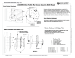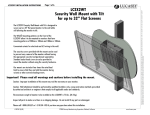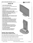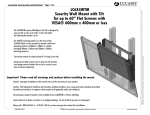
1
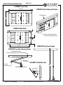
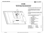
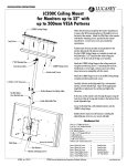
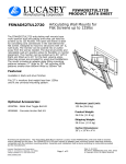
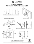
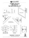
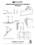
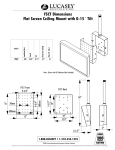
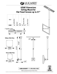
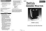
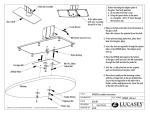
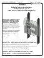
Page 1 of 5
LC200DS2
Double Stud Dual Articulating Wall Mount
for Flat Panel Screens up to 32"
with up to 200mm x 200mm VESA® Mounting Patterns
Multi-position triple pivoting arms allows you to position
the monitor in hard to reach areas. Use the LC200DS2
with flat screens up to 75 Pounds. Ideal for concealing
cord connections in the wall behind the flat screen.
Designed to mount to structures with 16" CL wall studs.
The monitor can be pushed into or pulled away from the
wall as needed. The dual pivot points and relocatable
wall arm position allow for flexibility in monitor placement.
The viewing angle can be adjusted 45 for the best
viewing angle.
Wood lag screws are provided for wood stud installations.
Concrete anchor bolts or Toggle bolts for metal studs
can be ordered separately using part numbers:
WMAAB6 or WMATB6.
Open pattern of wall plate allows access holes to be cut
into wall.
Important! Please read all warnings and cautions before installing the mount.
Caution: Improper installaion of this wall mount may void the warranty on your monitor.
Caution: Wall attachment should be performed by qualified installers only, using construction methods prescribed
by authorized architects or engineers that comply to all applicable codes and standards.
The maximum weight of each monitor to be installed on theLC200DS2 is 75Lbs. (34.1 Kg.)
Inspect all parts to make sure there is no shipping damage. Do not install if any parts are damaged.
Please call 1-800-LUCASEY or 1-510-534-1435 if you have any questions about this installation.
LC200DS2_Ins (1/07) DOC#20070003A
©2007 Lucasey Manufacturing Corporation, Oakland, California
www.lucasey.com
Protected under one or more of these U.S. Patent numbers: 3,291,432 3,559,942 3,724,798 DES.270,689 4,613,109 4,878,645 4,852,842 DES.309,5624,973,023 5,169,114 5,255,884 5,310,152 5,522,576 5,621,614 Re.35,677 DES.398,834 5,826,384 5,941,492 5,964,068 6,060,661 6,102,398 6,158,704 6,454,116B1 6,761,276B2 6,806,425B1
LC200DS2 INSTALLATION INSTRUCTIONS
Page 2 of 5
LC200DS2 INSTALLATION INSTRUCTIONS
WARNING: The structure to which the mount is attached needs to be capable of supporting five times the stated load limit.
Additional reinforcement of the structure to which the mount is attached may be necessary and a certified architect
or engineer is needed to make this determination.
WARNING: Take into consideration the combined weight of the mount, the monitor and any auxiliary equipment when
determining the total load on the wall and mount.
WARNING: Do not place body parts between movable parts on the LC200DS2 mount. The mount has pinch points that can
cause injury.
WARNING: Make sure that the screws used to attach the monitor to the mount are the appropriate size and length. An
assortment of monitor attaching screws is provided for convenience. The appropriate screws to use for mounting the
monitor are determined by the monitor manufacturer. Failure to use the screws recommended by the monitor manufacurer
can result in the montior dropping from the mount and/or damage to the electronic components inside the monitor.
Item List
Table of Contents
Page 1
Page 2
Page 3
Page 4
Page 5
...
...
...
...
...
Title Page & Product Description
Warnings, Item List & Tools Required
Dimensional Drawings
Installation Instructions for LC200DS2
Tilt Adjustment, Monitor Removal & Warranty
Tools Required
1/8" Hex Wrench
9/16" Box Wrench or Socket Driver
1/2" Box Wrench or Socket Driver
7/16" Box Wrench or Socket Driver
Phillips Screw Driver
LC200DS2_Ins (1/07) DOC#20070003A
1 ...
1 ...
1 ...
2 ...
2 ...
1 ...
4 ...
1 ...
1 ...
1 ...
3 ...
2 ...
2 ...
1 ...
1 ...
2 ...
4 ...
6 ...
LC200DS2 Wall Bracket Assembly
LC200DS2 Double Action Wall Arm
LC200DS2 Tilt Assembly with VESA® Mounting Plate
Top and Bottom Covers for Wall Bracket Assembly
Side Covers for Wall Bracket Assembly
3/8-16 x 9" Flanged Head Hex Bolt
3/8" Belleville Washers
3/8-16 Nylock Nut
5/16-18 x 2" Hex Button Head Screw
5/16-18 x 2-1/4" Hex Head Bolt
5/16" Flat Washers
5/16" Belleville Washers
5/16-18 Nylock Nuts
1/4-20 x 2" Hex Button Head Screw
1/4" Flat Washer
1/4" Belleville Washers
#8-32 x 3/8" Self Tapping Phillips Screws
#14 x 2-1/2" Lag Screws
Monitor Attaching Screw Assortment
6
12
6
12
6
12
6
36
6
18
6
...
...
...
...
...
...
...
...
...
...
...
4mm x 25mm Set Screws
4mm Hex Nuts
5mm x 30mm Set Screws
5mm Hex Nuts
6mm x 30mm Set Screws
6mm Hex Nuts
4mm x 12mm Phillips Screws
5mm Flat Washers
5mm x 12mm Phillips Screws
1/4" Flat Washers
6mm x 12mm Phillips Screws
©2007 Lucasey Manufacturing Corporation, Oakland, California
www.lucasey.com
Protected under one or more of these U.S. Patent numbers: 3,291,432 3,559,942 3,724,798 DES.270,689 4,613,109 4,878,645 4,852,842 DES.309,5624,973,023 5,169,114 5,255,884 5,310,152 5,522,576 5,621,614 Re.35,677 DES.398,834 5,826,384 5,941,492 5,964,068 6,060,661 6,102,398 6,158,704 6,454,116B1 6,761,276B2 6,806,425B1
WARNING: Improper installation can result in serious personal injury. It is the responsibility of the installer to ensure
that all safety precautions are taken during the installation and that all safety features of the mount are properly utilized.
Page 3 of 5
LC200DS2 INSTALLATION INSTRUCTIONS
LC200DS2 Front View
19-1/4"
3" Min. Projection
11-1/4"
LC200DS2 Wall Plate
5"
Inside arm folds past outside arms
for closest to the wall home position.
5"
16"
LC200DS2 Top View Straight
LC200DS2 Top View Showing Pivots
Pivot point for articulation
(Can be relocated for best monitor viewing locaiton)
Pivot point
for articulation
LC200DS2 Tilted Side View
Pivot point
for articulation
24.7"
45 Max. Tilt
LC200DS2_Ins (1/07) DOC#20070003A
©2007 Lucasey Manufacturing Corporation, Oakland, California
www.lucasey.com
Protected under one or more of these U.S. Patent numbers: 3,291,432 3,559,942 3,724,798 DES.270,689 4,613,109 4,878,645 4,852,842 DES.309,5624,973,023 5,169,114 5,255,884 5,310,152 5,522,576 5,621,614 Re.35,677 DES.398,834 5,826,384 5,941,492 5,964,068 6,060,661 6,102,398 6,158,704 6,454,116B1 6,761,276B2 6,806,425B1
LC200DS2 Fully Collapsed Position
LC200DS2 INSTALLATION INSTRUCTIONS
Page 4 of 5
Wall Bracket
Wood Lag Screws are provided for 16" on center wood stud
installations. If you are installing onto metal studs follow
the toggle bolt instructions on page 5. If installing into
concrete, use our WMAAB6, concrete anchor bolt kit.
See http://www.lucasey.com for details and drawings of
all available mount accessories.
1. Determine the proper height and viewing location for the
monitor taking into consideration the proper ceiling and head
clearance for the monitor being mounted. Also, consider
where the monitor pivot point location will be placed and the
final desired viewing angle for the monitor.
Lag Screws
2. Find the location of the center of two wood studs 16"
appart using a stud finder. Using the LC200DS2 Wall Bracket
as a template, mark the location for the six Wood Lag Screws.
3. Using a 1/8" Drill bit, drill the six pilot holes 2-3/4" deep
at the marked locations on the wall.
3/8" Threaded Bolt
3/8" Belleville Washers
(Curved side down)
3/8" Belleville Washers
(Curved side up)
3/8" Nylock Nut
Monitor Attaching Screw
Flat Washer
LC200DS2 VESA® Mounting Plate
Wall Arm Tubing
Monitor Threaded Insert
4. Attach the Wall Bracket to the wall using the provided
Wood Lag Screws or Toggle Bolt Machine Screws. Make
sure all the screws are tight before proceeding with the
remainder of the installation.
Wall Arm Attachment
1. Using the pivot position determined from step 1 in mounting
the Wall Bracket place the Wall Arm in the proper pivot hole
position.
2. Insert the 3/8" Threaded Bolt through the Wall Bracket
and Wall Arm Tubing.
3. Secure the Wall Arm using the 3/8" Spacer, 3/8" Belleville
Washers and Nyclock Nut as shown.
4. Adjust the tension of the 3/8" Nylock Jam Nut to keep
the monitor from swinging unintentionally.
Monitor Attachment
Determine which type of monitor attaching hardware is required
for the monitor as specified by the monitor manufacturer.
Various sizes of monitor attaching screws are provided for
convenience.
1. Use fasteners as specified by the monitor manufacturer to
attach the monitor directly to the LC200DS2 VESA® Mounting
Plate.
2. Ensure that the monitor attaching hardware is securely
fastened and tight and that none of the threaded inserts are
damaged in any way.
LC200DS2_Ins (1/07) DOC#20070003A
©2007 Lucasey Manufacturing Corporation, Oakland, California
www.lucasey.com
Protected under one or more of these U.S. Patent numbers: 3,291,432 3,559,942 3,724,798 DES.270,689 4,613,109 4,878,645 4,852,842 DES.309,5624,973,023 5,169,114 5,255,884 5,310,152 5,522,576 5,621,614 Re.35,677 DES.398,834 5,826,384 5,941,492 5,964,068 6,060,661 6,102,398 6,158,704 6,454,116B1 6,761,276B2 6,806,425B1
Wall Bracket Mounting
Page 5 of 5
LC200DS2 Tilted Side View
Monitor Tilt Adjustment
1. Carefully loosen, but do not remove, theTilt Adjustment
Screw. Do not loosen more than is needed to make the
monitor moveable. See Detail A.
2. Slide the monitor into the appropriate viewing angle
45 .
C
3. Tighten the Tilt Adjustment Screw and make sure the
monitor can not be moved.
Monitor Removal
Detail A
1. With one person holding the monitor in place,
have a second person remove the 5/16-18 Hex
Bolt from the mount Pivot Point.
2. Carefully lower the monitor to the ground and
remove the mounting plate from the monitor.
5/16-18 Hex Bolt
B
Pivot Point
Detail B
LIMITED WARRANTY
LUCASEY MANUFACTURING CORPORATION MAKES NO WARRANTY OF ANY KIND, EXPRESS OR IMPLIED except that the goods sold under this agreement
shall be free of defects in materials and workmanship for a period of one year from the user's date of purchase. User assumes all risk and liability
resulting from the use of the goods, whether used singly or in combination with other goods. Lucasey Manufacturing Corporation neither assumes
nor authorizes any person to assume for it any other liability in connection with the sale or use of the goods sold and there are no oral agreements
or warranties collateral to or affecting this limited warranty. Lucasey Manufacturing Corporation will repair or replace defective parts or equipment
within one year of the date of purchase, at its option, provided the part or equipment is returned pre-paid to Lucasey Manufacturing Corporation's
plant. The repaired or replaced part shall be shipped to the user, FOB Lucasey Manufacturing Corporation's plant. NO allowance for outside labor
charges are implied within the terms of this limited warranty. Under no circumstances will Lucasey Manufacturing Corporation be responsible for
special, indirect or consequential damages. The remedies set forth in this Limited Warranty are exclusive and the liability of Lucasey Manufacturing
Corporation with respect to any contract of sale or anything done in connection therewith, whether in contract, in tort, under any warranty or
otherwise shall not, except as expressly provided herein, exceed the price of the equipment or part on which such liability is based. Any damage
caused by the improper use, operation beyond capacity, substitution of parts or equipment not approved by Lucasey Manufacturing Corporation,
improper packaging, failure to observe installation or other instructions, transit, or repair by one other than Lucasey Manufacturing Corporation,
will not be covered by and shall void this Limited Warranty.
LC200DS2_Ins (1/07) DOC#20070003A
©2007 Lucasey Manufacturing Corporation, Oakland, California
www.lucasey.com
Protected under one or more of these U.S. Patent numbers: 3,291,432 3,559,942 3,724,798 DES.270,689 4,613,109 4,878,645 4,852,842 DES.309,5624,973,023 5,169,114 5,255,884 5,310,152 5,522,576 5,621,614 Re.35,677 DES.398,834 5,826,384 5,941,492 5,964,068 6,060,661 6,102,398 6,158,704 6,454,116B1 6,761,276B2 6,806,425B1
LC200DS2 INSTALLATION INSTRUCTIONS