1
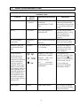
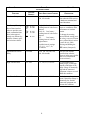
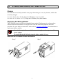
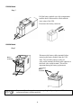
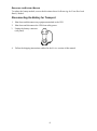
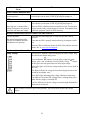
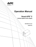
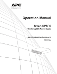
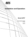
Installation and Operation
Smart-UPS®
SUA1000-BR/SUA1500-BR
120 VAC
English
This manual and the safety guide are available in English on the enclosed CD and the APC Web site, www.apc.com.
Este manual e o guia de segurança estão disponíveis em português no CD incluso e no website da APC, www.apc.com.
Introduction
The APC® by Schneider Electric Smart-UPS® is a high performance uninterruptible power supply
(UPS). It provides protection for electronic equipment from utility power blackouts, brownouts, sags,
and surges; small utility fluctuations and large disturbances. The UPS also provides battery backup
power until utility power returns to safe levels or the batteries are fully discharged.
1:
INSTALLATION
Read the Safety Instruction sheet before installing the UPS.
Unpacking
Inspect the UPS upon receipt. APC designed robust packaging for your product. However, accidents
and damage may occur during shipment. Notify the carrier and dealer if there is damage.
The packaging is recyclable; save it for reuse or dispose of it properly.
Check the package contents. The package contains the UPS, a literature kit containing one CD, one
serial cable, one USB cable, product documentation and Safety Information.
The UPS is shipped with the battery disconnected.
Positioning the UPS
The UPS is heavy. Select a location sturdy enough to handle the weight.
Do not operate the UPS where there is excessive dust or the temperature and humidity are outside the
specified limits.
PLACEMENT
0º- 40ºC (32º-104ºF)
0-95% Relative
Humidity
2.5cm (1in)
1
Connecting Equipment and Power to the UPS
SMART-UPS REAR PANEL
Y
X
1.
Plug in the battery connectorn.
2.
Connect equipment to the UPS. Note: Do not connect a laser printer to the UPS. A laser
printer draws significantly more power than other types of equipment and may overload
the UPS.
3.
Add any optional accessories to the SmartSlotY.
4.
Using the power cord, plug the UPS into a two-pole, three-wire, grounded receptacle only.
Avoid using extension cords.
5.
Turn on all connected equipment. To use the UPS as a master ON/OFF switch, be sure all
connected equipment is switched ON. The equipment will not be powered until the UPS is
turned on.
6.
To power up the UPS press the
7.
button on the front panel.
•
The UPS charges its battery when it is connected to utility power. The battery charges to
90% capacity during the first three hours of normal operation. Do not expect full battery run
capability during this initial charge period.
•
Check the site wiring fault LED located on the rear panel. It lights up if the UPS is plugged
into an improperly wired utility power outlet. Refer to Troubleshooting in this manual.
®
For additional computer system security, install PowerChutePlus UPS Power Management and
Diagnostic Software.
2
BASIC CONNECTORS
Serial Port
USB Port
Power management software and interface kits can be used
with the UPS. Use only interface kits supplied or approved
by APC.
Use the APC supplied cable to connect to the Serial Port. DO NOT use a standard
serial interface cable since it is incompatible with the UPS connector.
Both Serial and USB Ports are provided. They cannot be used simultaneously.
TVSS Screw
The UPS features a transient voltage surge-suppression (TVSS) screw for
connecting the ground lead on surge suppression devices such as
telephone and network line protectors.
When connecting grounding cable, disconnect the unit from the utility
power outlet.
2:
OPERATION
SMART-UPS FRONT PANEL
Power On
Power Off
Online
The online LED illuminates when the UPS is supplying utility power
to the connected equipment. If the LED is not lit, the UPS is either not
turned ON, or is supplying battery power.
AVR Trim
This LED illuminates to indicate the UPS is compensating for a high
utility voltage.
AVR Boost
This LED illuminates to indicate the UPS is compensating for a low
utility voltage.
3
On Battery
When the on battery power LED is lit the UPS is supplying battery
power to the connected equipment. When on battery, the UPS sounds
an alarm—four beeps every 30 seconds.
Overload
The LED illuminates and the UPS emits a sustained alarm tone when
an overload condition occurs.
Replace Battery
Failure of a battery self-test causes the UPS to emit short beeps for
one minute and the replace battery LED illuminates.
Refer to Troubleshooting in this manual.
Battery
Disconnected
The replace battery LED flashes and short beep is emitted every two
seconds to indicate the battery is disconnected.
Automatic Self-Test
The UPS performs a self-test automatically when turned on, and every
two weeks thereafter (by default).
During the self-test, the UPS briefly operates the connected
equipment on battery.
lights and
If the UPS fails the self-test, the replace battery LED
immediately returns to online operation. The connected equipment is
not affected by a failed test. Recharge the battery for 24 hours and
perform another self-test. If it fails, the battery must be replaced.
Manual Self-Test
Press and hold the
self-test.
button for a few seconds to initiate the
On Battery Operation
The Smart-UPS switches to battery operation automatically if the utility power fails. While running
on battery, an alarm beeps four times every 30 seconds.
button (front panel) to silence the UPS alarm (for the current alarm only. If the utility
Press the
power does not return, the UPS continues to supply power to the connected equipment until the
battery is exhausted.
If PowerChute is not being used you must manually save your files and power down before the UPS
turns off.
DETERMINING ON BATTERY RUN TIME
UPS battery life differs based on usage and environment. It is recommended that the battery/batteries
be changed once every three years. See the APC Web site, www.apc.com, for on battery run times.
4
3:
USER CONFIGURABLE ITEMS
NOTE: SETTINGS ARE MADE THROUGH SUPPLIED POWERCHUTE SOFTWARE OR OPTIONAL SMART SLOT
ACCESSORY CARDS.
FUNCTION
FACTORY
DEFAULT
USER SELECTABLE CHOICES
DESCRIPTION
Automatic Self-Test
Every 14 days
(336 hours)
Every 7 days
(168 hours),
On Startup Only, No SelfTest
This function sets the
interval at which the UPS
will execute a self-test. Refer
to your software manual for
details.
UPS ID
UPS_IDEN
Up to eight characters to
define the UPS
Use this field to uniquely
identify the UPS, (ie. server
name or location) for
network management
purposes.
Date of Last Battery
Replacement
Manufacture
Date
Date of Battery Replacement
Reset this date when you
replace the battery module.
Minimum Capacity Before Return from Shutdown
0 percent
0, 15, 30, 45, 50, 60,
75, 90 percent
The UPS will charge its
batteries to the specified
percentage before return
from a shutdown.
Brightly lit: UPS is set to
high sensitivity (default).
To change the UPS
sensitivity, press the voltage
(rear
sensitivity button
panel). Use a pointed object
(such as a pen) to do so.
Voltage Sensitivity
The UPS detects and
reacts to line voltage
distortions by transferring
to battery operation to
protect the connected
equipment. Where power
quality is poor, the UPS
may frequently transfer to
battery operation. If the
connected equipment can
operate normally under
such conditions, reduce
the sensitivity setting to
conserve battery capacity
and service life.
Alarm Control
mm/dd/yy
Dimly lit: UPS is set to
medium sensitivity.
Off:
Low battery
warning interval is about
eight minutes.
Enable
Enable, Mute, Disable
5
You can change the
sensitivity level through
PowerChute software.
User can mute an ongoing
alarm or disable all existing
alarms permanently.
NOTE: SETTINGS ARE MADE THROUGH SUPPLIED POWERCHUTE SOFTWARE OR OPTIONAL SMART SLOT
ACCESSORY CARDS.
FUNCTION
Shutdown Delay
FACTORY
DEFAULT
90 seconds
Low Battery Warning.
PowerChute interface
software provides automatic, unattended shutdown when approximately two minutes (by
default) of battery operated run time remains.
USER SELECTABLE CHOICES
DESCRIPTION
0, 90, 180, 270, 360, 450,
540, 630 seconds
Sets the interval between the
time when the UPS receives
a shutdown command and
actual shutdown.
Brightly lit: Low battery
warning interval is about two
minutes.
Dimly lit: Low battery
warning interval is about five
minutes.
Off:
Low battery
warning interval is about
eight minutes.
The low battery warning
beeps are continuous when
two minutes of run time
remain.
Possible interval settings:
2, 5, 8, 11, 14, 17, 20,
23 minutes.
To change the warning
interval default setting, press
the voltage sensitivity button
(use a pointed object such as
a pen to do so), while
pressing and holding the
button (front panel).
Synchronized Turn-on
Delay
0 seconds
0, 60, 120, 180, 240, 300,
360, 420 seconds
The UPS will wait the
specified time after the
return of utility power before
turn-on (to avoid branch
circuit overload).
High Transfer Point
127 VAC
127, 130, 133, 136 VAC
To avoid unnecessary
battery usage, set the high
transfer point higher if the
utility voltage is chronically
high and the connected
equipment is known to work
under this condition.
Low Transfer Point
106 VAC
97, 100, 103, 106 VAC
Set the low transfer point
lower if the utility voltage is
chronically low and the
connected equipment can
tolerate this condition.
6
4:
STORAGE, MAINTENANCE, AND TRANSPORTING
Storage
Store the UPS covered and positioned as for proper functioning, in a cool, dry location, with the batteries fully charged.
At -15 to +30 °C (+5 to +86 °F), charge the UPS battery every six months.
At +30 to +45 °C (+86 to +113 °F), charge the UPS battery every three months.
Replacing the Battery Module
This UPS has an easy to replace, hot-swappable battery module. Replacement is a safe procedure,
isolated from electrical hazards. You may leave the UPS and connected equipment on for this
procedure. See your dealer or contact APC at the web site, www.apc.com/support for information on
replacement battery modules.
Once the battery is disconnected, the connected equipment is not protected from
power outages.
Be careful during the following steps-the battery module is heavy.
REMOVING THE FRONT BEZEL AND BATTERY MODULE
Step 1
Step 2
7
1500VA Model
Step 3
Pull the battery module out of the compartment
until the back of the module is flush with the
outer edges of the UPS.
Disconnect the battery connector.
Step B
Step A
1000VA Model
Step 3
Disconnect the battery cable terminals before
removing the battery module from the UPS.
Battery
Terminals
Note: The red cable connects to the red
color-coded terminal; the black cable connects to
the black color-coded terminal. This will be
important during the battery replacement
procedure.
Battery
Terminals
Be sure to deliver the spent battery to a recycling facility or ship it to APC in the
replacement battery packing material.
8
REPLACING THE BATTERY MODULE
To replace the battery module, reverse the directions above for Removing the Front Bezel and
Battery Module.
Disconnecting the Battery for Transport
1.
Shut down and disconnect any equipment attached to the UPS.
2.
Shut down and disconnect the UPS from utility power.
3.
Unplug the battery connector
(rear panel).
4.
Follow the shipping instructions outlined in the Service section of this manual.
9
5:
TROUBLESHOOTING
Use the chart below to solve minor Smart-UPS installation and operation problems. Refer to the APC
Web site, www.apc.com, for assistance with complex UPS problems.
SOLUTION
PROBLEM AND POSSIBLE
CAUSE
UPS WILL NOT TURN ON
Battery not connected properly.
Check that the battery connector (rear panel) is fully engaged.
button not pushed.
Press the
button once to power the UPS and the connected equipment.
UPS not connected to utility
power supply.
Check that the power cable from the UPS to the utility power supply is
securely connected at both ends.
Very low or no utility voltage.
Check the utility power supply to the UPS by plugging in a table lamp.
If the light is very dim, have the utility voltage checked.
UPS WILL NOT TURN OFF
Internal UPS fault.
UPS BEEPS OCCASIONALLY
Normal UPS operation.
Do not attempt to use the UPS. Unplug the UPS and have it serviced
immediately.
None. The UPS is protecting the connected equipment.
UPS DOES NOT PROVIDE EXPECTED BACKUP TIME
The UPS battery is weak due
Charge the battery. Batteries require recharging after extended outages.
to a recent outage or is near
They wear faster when put into service often or when operated at elevated
the end of its service life.
temperatures. If the battery is near the end of its service life, consider
replacing the battery even if the replace battery LED is not yet lit.
ALL LEDS ARE LIT AND THE UPS EMITS A CONSTANT BEEPING
Internal UPS fault.
Do not attempt to use the UPS. Turn the UPS off and have it serviced
immediately.
FRONT PANEL LEDS FLASH SEQUENTIALLY
None. The UPS will restart automatically when utility power returns.
The UPS has been shut down
remotely through software or
an optional accessory card.
ALL LEDS ARE OFF AND THE UPS IS PLUGGED INTO A WALL OUTLET
The UPS is shut down and the
None. The UPS will return to normal operation when the power is restored
and the battery has a sufficient charge.
battery is discharged from an
extended outage.
10
SOLUTION
PROBLEM AND POSSIBLE
CAUSE
THE OVERLOAD LED IS LIT AND THE UPS EMITS A SUSTAINED ALARM TONE
The UPS is overloaded.
The connected equipment exceeds the specified “maximum load” as
defined in Specifications at the APC web site, www.apc.com.
The alarm remains on until the overload is removed. Disconnect
nonessential equipment from the UPS to eliminate the overload.
The UPS continues to supply power as long as it is online and the circuit
breaker does not trip; the UPS will not provide power from batteries in the
event of a utility voltage interruption.
If a continuous overload occurs while the UPS is on battery, the unit turns
off output in order to protect the UPS from possible damage.
THE REPLACE BATTERY LED IS LIT
Check that the battery connectors are fully engaged.
Replace Battery LED flashes
and short beep is emitted every
two seconds to indicate the
battery is disconnected.
Weak battery.
Allow the battery to recharge for 24 hours. Then, perform a self-test. If the
problem persists after recharging, replace the battery.
Failure of a battery self-test.
The UPS emits short beeps for one minute and the replace battery LED
illuminates. The UPS repeats the alarm every five hours. Perform the
self-test procedure after the battery has charged for 24 hours to confirm the
replace battery condition. The alarm stops and the LED clears if the
battery passes the self-test.
THE SITE WIRING FAULT LED IS LIT
The UPS is plugged into an improperly wired utility power outlet. Wiring
The site wiring LED is lit
faults detected include missing ground, hot-neutral polarity reversal, and
(rear panel).
overloaded neutral circuit. Contact a qualified electrician to correct the
building wiring.
120V models only.
THE INPUT CIRCUIT BREAKER TRIPS
The plunger on the circuit
Reduce the load on the UPS by unplugging equipment and press the
breaker (located above the input plunger in.
cable connection) pops out.
AVR BOOST OR AVR TRIM LEDS LIGHT
AVR Boost or Trim LEDs light Have qualified service personnel check your facility for electrical
problems. If the problem continues, contact the utility company for further
Your system is experiencing
assistance.
excessive periods of low r high
voltage.
11
PROBLEM AND POSSIBLE
CAUSE
SOLUTION
UTILITY CIRCUIT BREAKER TRIPS
Utility circuit breaker trips during
normal operation.
Reduce the load on the UPS by unplugging equipment and resetting the
circuit breaker (on the back of UPS) by pressing the plunger in.
UPS OPERATES ON BATTERY ALTHOUGH NORMAL LINE VOLTAGE EXISTS
UPS input circuit breaker tripped.
Reduce the load on the UPS by unplugging equipment and resetting the
circuit breaker (on the back of UPS) by pressing the plunger in.
Very high, low, or distorted line
voltage. Inexpensive fuel powered
generators can distort the voltage.
Move the UPS to a different outlet on a different circuit. Test the input
voltage with the utility voltage display (see below). If acceptable to the
connected equipment, reduce the UPS sensitivity.
BATTERY CHARGE AND BATTERY LOAD LEDS FLASH SIMULTANEOUSLY
UPS has shutdown.
The internal temperature of the
UPS has exceeded the allowable
threshold for safe operation.
Check that the room temperature is within the specified limits for
operation.
Check that the UPS is properly installed allowing for adequate ventilation.
Allow the UPS to cool down. Restart the UPS. If the problem continues
contact APC at, www.apc.com/supoport.
DIAGNOSTIC UTILITY VOLTAGE FEATURE
The UPS has a diagnostic feature that displays the utility voltage. Plug
Utility Voltage
the UPS into the normal utility power.
Press and hold the
button to view the utility voltage bar graph
display
display. After a few seconds the five-LED, Battery Charge
on the right of the front panel shows the utility input voltage.
Refer to the figure at left for the voltage reading (values are not listed on
the UPS).
The display indicates the voltage is between the displayed value on the
list and the next higher value.
Three LEDs light, indicating utility voltage within the normal range.
If no LEDs are lit and the UPS is plugged into a working utility power
outlet, the line voltage is extremely low.
If all five LEDs are lit, the line voltage is extremely high and should be
checked by an electrician.
The UPS starts a self-test as part of this procedure. The self-test does not affect the voltage
display.
12
Service
If the unit requires service, do not return it to the dealer. Follow these steps:
1. Review the Troubleshooting section of the manual to eliminate common problems.
2. If the problem persists, contact APC Customer Support through the APC Web site,
www.apc.com.
a. Note the model number and serial number and the date of purchase. The serial number is
located on the rear panel of the unit and is available through the LCD display on select
models.
b. Call APC Customer Support and a technician will attempt to solve the problem over the
phone. If this is not possible, the technician will issue a Returned Material Authorization
Number (RMA#).
c. If the unit is under warranty, the repairs are free.
d. Service procedures and returns may vary internationally. Refer to the APC Web site for
country specific instructions.
3. Pack the unit in its original packaging. If this is not available, refer to www.apc.com to obtain
a new set.
a. Pack the unit properly to avoid damage in transit. Never use foam beads for packaging.
Damage sustained in transit is not covered under warranty.
b. For the UPS, always DISCONNECT THE BATTERY before shipping in compliance with U.S. Department of Transportation (DOT) and IATA regulations. The
battery may remain in the unit.
c. Internal batteries may remain connected in the XLBP during shipment, (if applicable,
not all units have XLBPs).
4. Write the RMA# provided by Customer Support on the outside of the package.
5. Return the unit by insured, pre-paid carrier to the address provided by Customer Support.
APC Worldwide Customer Support
Refer to www.apc.com (Corporate Headquarters)
Connect to localized APC Web sites for specific countries, each of which provides customer
support information.
Contact the APC Customer Support Center by telephone or e-mail.
Telephone: Global (888) 272 2782
Brazil (11) 4689 8600
13
6:
RADIO FREQUENCY WARNINGS AND WARRANTY
This device complies with FCC Part 15 Class A requirements. Operation is subject to the following
two conditions: (1) this device may not cause harmful interference and (2) this device must accept
any interference received, including interference that may cause undesired operation.
Limited Warranty
The limited warranty provided by American Power Conversion (APC®) in this Statement of Limited
Factory Warranty applies only to Products you purchase for your commercial or industrial use in the
ordinary course of your business.
Terms of Warranty
APC warrants its products to be free from defects in materials and workmanship for a period of two
years from the date of purchase. The APC obligation under this warranty is limited to repairing or
replacing, at its sole discretion, any such defective products. This warranty does not apply to
equipment that has been damaged by accident, negligence or misapplication or has been altered or
modified in any way. Repair or replacement of a defective product or part thereof does not extend the
original warranty period. Any parts furnished under this warranty may be new or factory
remanufactured.
Non-transferable Warranty
This warranty applies only to the original purchaser who must have properly registered the product.
Product may be registered at www.apc.warranty.com.
Exclusions
APC shall not be liable under the warranty if its testing and examination disclose that the alleged
defect in the product does not exist or was caused by end user or any third person misuse, negligence,
improper installation or testing. Further APC shall not be liable under the warranty for unauthorized
attempts to repair or modify wrong or inadequate electrical voltage or connection, inappropriate onsite operation conditions, corrosive atmosphere, repair, installation, start-up by non-APC designated
personnel, a change in location or operating use, exposure to the elements, Acts of God, fire, theft, or
installation contrary to APC recommendations or specifications or in any event if the APC serial
number has been altered, defaced, or removed, or any other cause beyond the range of the intended
use.
THERE ARE NO WARRANTIES, EXPRESS OR IMPLIED, BY OPERATION OF LAW
OR OTHERWISE, OF PRODUCTS SOLD, SERVICED OR FURNISHED UNDER THIS
AGREEMENT OR IN CONNECTION HEREWITH. APC DISCLAIMS ALL IMPLIED
WARRANTIES OF MERCHANTABILITY, SATISFACTION AND FITNESS FOR A
PARTICULAR PURPOSE. APC EXPRESS WARRANTIES WILL NOT BE
ENLARGED, DIMINISHED, OR AFFECTED BY AND NO OBLIGATION OR
LIABILITY WILL ARISE OUT OF, APC RENDERING OF TECHNICAL OR OTHER
ADVICE OR SERVICE IN CONNECTION WITH THE PRODUCTS. THE
FOREGOING WARRANTIES AND REMEDIES ARE EXCLUSIVE AND IN LIEU OF
ALL OTHER WARRANTIES AND REMEDIES. THE WARRANTIES SET FORTH
ABOVE CONSTITUTE APC SOLE LIABILITY AND PURCHASER’S EXCLUSIVE
14
REMEDY FOR ANY BREACH OF SUCH WARRANTIES. APC WARRANTIES RUN
ONLY TO PURCHASER AND ARE NOT EXTENDED TO ANY THIRD PARTIES.
IN NO EVENT SHALL APC, ITS OFFICERS, DIRECTORS, AFFILIATES OR EMPLOYEES
BE LIABLE FOR ANY FORM OF INDIRECT, SPECIAL, CONSEQUENTIAL OR PUNITIVE
DAMAGES, ARISING OUT OF THE USE, SERVICE OR INSTALLATION, OF THE
PRODUCTS, WHETHER SUCH DAMAGES ARISE IN CONTRACT OR TORT, IRRESPECTIVE OF FAULT, NEGLIGENCE OR STRICT LIABILITY OR WHETHER APC HAS
BEEN ADVISED IN ADVANCE OF THE POSSIBILITY OF SUCH DAMAGES.
SPECIFICALLY, APC IS NOT LIABLE FOR ANY COSTS, SUCH AS LOST PROFITS OR
REVENUE, LOSS OF EQUIPMENT, LOSS OF USE OF EQUIPMENT, LOSS OF
SOFTWARE, LOSS OF DATA, COSTS OF SUBSTITUANTS, CLAIMS BY THIRD
PARTIES, OR OTHERWISE.
NO SALESMAN, EMPLOYEE OR AGENT OF APC IS AUTHORIZED TO ADD TO OR
VARY THE TERMS OF THIS WARRANTY. WARRANTY TERMS MAY BE MODIFIED,
IF AT ALL, ONLY IN WRITING SIGNED BY AN APC OFFICER AND LEGAL
DEPARTMENT.
Warranty Claims
Customers with warranty claims issues may access the APC worldwide customer support network by
referring to the APC Web site, www.apc.com . Select your country from the country selection
pull-down menu. Open the Support tab at the top of the web page to obtain contact information for
customer support in your region.
1
To determine which factory warranty applies to the APC product you purchased, consult the factory
warranties located on the APC Web site, www.apc.com/products.
© 2009 APC by Schneider Electric. APC, the APC logo, and Smart-UPS are owned by Schneider Electric Industries
S.A.S., American Power Conversion Corporation, or their affiliated companies. All other trademarks are property of
their respective owners.
15
990-3828
12/2009