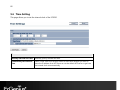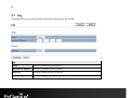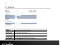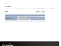
1
1 11N Long Range Multi-Function Gigabit CB / AP ECB350 11N Long Range Multi-Function Gigabit CB / AP V1.0 1 Table of Contents 1 Introduction ....................................................................................................................................................................... 5 1.1 1.2 1.3 1.4 2 Before you Begin ............................................................................................................................................................... 9 2.1 2.2 2.3 2.4 3 Default Settings ................................................................................................................................................................................................. 16 Web Configuration........................................................................................................................................................................................... 17 Building a Wireless Network ......................................................................................................................................... 19 4.1 4.2 4.3 4.4 4.5 4.6 4.7 5 Considerations for Wireless Installation .....................................................................................................................................................9 Computer Settings (Windows XP/Windows 7) ..................................................................................................................................... 10 Apple Mac X OS................................................................................................................................................................................................. 13 Hardware Installation ...................................................................................................................................................................................... 14 Configuring Your Client Bridge ..................................................................................................................................... 16 3.1 3.2 4 Features and Benefits .........................................................................................................................................................................................5 Package Contents ................................................................................................................................................................................................6 System Requirements.........................................................................................................................................................................................7 Applications............................................................................................................................................................................................................7 Client Bridge Mode .......................................................................................................................................................................................... 19 Client Router Mode.......................................................................................................................................................................................... 20 Access Point Mode ........................................................................................................................................................................................... 21 Access Point Router Mode ............................................................................................................................................................................ 22 WDS AP / WDS Station Mode...................................................................................................................................................................... 23 WDS Bridge Mode ............................................................................................................................................................................................ 24 Repeater mode .................................................................................................................................................................................................. 25 Status ................................................................................................................................................................................ 26 5.1 5.2 Save/Reload......................................................................................................................................................................................................... 26 Main........................................................................................................................................................................................................................ 27 2 5.3 5.4 5.5 6 System .............................................................................................................................................................................. 32 6.1 6.2 6.3 7 Operation Mode................................................................................................................................................................................................ 32 IP Settings ............................................................................................................................................................................................................ 33 Spanning Tree Setting..................................................................................................................................................................................... 34 Router ............................................................................................................................................................................... 36 7.1 7.1.1 7.1.2 7.1.3 7.1.4 7.2 7.3 7.4 7.5 7.6 7.7 7.8 7.9 8 Connection Status............................................................................................................................................................................................. 29 Wireless Client List............................................................................................................................................................................................ 30 System Log .......................................................................................................................................................................................................... 31 WAN Settings ..................................................................................................................................................................................................... 36 Static IP............................................................................................................................................................................................................. 36 DHCP ................................................................................................................................................................................................................. 39 PPPoE ................................................................................................................................................................................................................ 41 PPTP ................................................................................................................................................................................................................... 43 LAN Settings........................................................................................................................................................................................................ 45 VPN Pass Through ............................................................................................................................................................................................ 46 Port Forwarding ................................................................................................................................................................................................. 47 Port Triggering ................................................................................................................................................................................................... 49 DMZ........................................................................................................................................................................................................................ 51 MAC Filter............................................................................................................................................................................................................. 52 IP Filter................................................................................................................................................................................................................... 53 URL Filter .............................................................................................................................................................................................................. 55 Wireless ............................................................................................................................................................................ 56 8.1 8.2 8.3 8.4 8.5 Wireless Network .............................................................................................................................................................................................. 56 Wireless Security ............................................................................................................................................................................................... 60 Site Survey ........................................................................................................................................................................................................... 63 Wireless MAC Filter .......................................................................................................................................................................................... 67 Wireless Advanced ........................................................................................................................................................................................... 68 3 8.6 8.7 9 WPS (Wi-Fi Protected Setup)........................................................................................................................................................................ 70 WDS Link Settings............................................................................................................................................................................................. 72 Management.................................................................................................................................................................... 74 9.1 9.2 9.3 9.4 9.5 9.6 9.7 9.8 9.9 9.10 9.11 Administration.................................................................................................................................................................................................... 74 Management VLAN.......................................................................................................................................................................................... 75 SNMP Settings ................................................................................................................................................................................................... 76 Backup/Restore.................................................................................................................................................................................................. 78 Firmware Upgrade ............................................................................................................................................................................................ 79 Time Setting ........................................................................................................................................................................................................ 80 Log .......................................................................................................................................................................................................................... 81 Diagnostics .......................................................................................................................................................................................................... 82 LED Control.......................................................................................................................................................................................................... 83 Logout ................................................................................................................................................................................................................... 84 Reset....................................................................................................................................................................................................................... 85 Appendix A – FCC Interference Statement .......................................................................................................................... 86 Appendix B – IC Interference Statement ............................................................................................................................. 87 Appendix C – CE Interference Statement............................................................................................................................. 89 4 Revision History Version 1.0 Date 2012/02/22 Notes First Release 5 1 Introduction The ECB350 is a multi-function 802.11b/g/n product with 8 major multi-functions. The ECB350 is designed to operate in every working environment including enterprises. The ECB350 is a Wireless Network device that delivers up to 6x faster speeds and 7x extended coverage than 802.11b/g devices. The ECB350 supports use in the home network with superior throughput, performance, and significant wireless range. To protect data during wireless transmissions, the ECB350 encrypts all wireless transmissions through WEP data encryption and supports WPA/WPA2 encryption. The ECB350 has MAC address filtering to allow users to select differing stations to access the network. The ECB350 is an ideal product to ensure network safety for both home and enterprise environments. 1.1 Features and Benefits Features Benefits High Speed Data Rate Up to 300 Mbps Capable of handling heavy data payloads such as HD multimedia streaming. 10/100/1000 Fast Ethernet Support up to 1000Mbps networking speed. IEEE 802.11n Draft Compliant and Backwards Compatible with 802.11b/g devices Fully compatible with IEEE 802.11b/g/n devices. Multi-Function Allowing users to select Access Point, Client Bridge, WDS AP, WDS Bridge, WDS Station, Universal Repeater, Router or Client Router mode in various applications. Point-to-Point or Point-to-Multipoint Wireless Connectivity Allows transfer of data from building to building. 6 Support Multiple SSID in AP mode (up to 4) Allow clients to access different networks through a single access point and assign different policies and functions for each SSID through the built in software. WPA/WPA2/IEEE 802.1x Support Powerful data security. MAC Address Filtering in AP Mode Ensure a secure network connection. User Isolation Support (AP mode) Protect the private network between client users. Power-over-Ethernet (IEEE802.3af) Flexible Access Point locations. Save User Settings Firmware upgrade does not delete user settings. SNMP Remote Configuration Management Allows remote connection to configure or manage the ECB350 easily. QoS (WMM) support Enhanced user performance and density. 1.2 Package Contents The ECB350 package contains the following items (all items must be in package to issue a refund): ECB350 Wireless Long Range Multi-Function CB / AP 12V/1A 100V~240V Power Adapter RJ-45 Ethernet LAN Cable CD-ROM with User's Manual Quick User Guide 7 1.3 System Requirements The following are the minimum system requirements in order configure the device. Computer with an Ethernet interface or Wireless Network function Windows OS (XP, Vista, 7), Mac OS, or Linux based operating systems Web-Browsing Application (i.e.: Internet Explorer, FireFox, Safari, or other similar software) 1.4 Applications Wireless LAN products are easy to install and highly efficient. The following list describes some of the many applications made possible through the power and flexibility of wireless LANs: a) Difficult-to-Wire Environments There are many situations where wires cannot be laid easily or cannot be hidden from view. Older buildings, sites with multiple buildings, and/or areas make the installation of a Wired LAN impossible, impractical, and/or expensive. b) Temporary Workgroups Create temporary workgroups/networks in open areas such as parks, athletic arenas, exhibition centers, temporary offices, and construction sites where one wants a temporary Wireless LAN established and easily removed. c) The Ability to Access Real-Time Information Doctors/Nurses, Point-of-Sale Employees, and/or Warehouse Workers can access real-time information while dealing with patients, serving customers, and/or processing information. d) Frequently Changing Environments Set up networks in environments that change frequently (i.e.: Show Rooms, Exhibits, etc.). e) Small Office and Home Office (SOHO) Networks SOHO users need a cost-effective, easy and quick installation of a small network. 8 f) Wireless Extensions to Ethernet Networks Extend network coverage where the network cannot reach (i.e.: There is no wired internet connection to reach certain location of the environment). g) Wired LAN Backup Implement wireless LANs to provide backup for mission-critical applications running on wired networks. h) Training/Educational Facilities Training sites at corporations or students at universities use wireless connectivity to ease access to information, information exchanges, and learning. 9 2 Before you Begin This section will guide you through the installation process. Placement of the ENGENIUS ECB350 is essential to maximize the ECB350’s performance. Avoid placing the ECB350 in an enclosed space such as a closet, cabinet, or wardrobe. 2.1 Considerations for Wireless Installation The operating distance of all wireless devices cannot be pre-determined due to a number of unknown obstacles in the environment that the device is deployed in. These could be the number, thickness, and location of walls, ceilings, or other objects that the ECB350’s wireless signals must pass through. Here are some key guidelines to allow the ECB350 to have optimal wireless range. Keep the number of walls and/or ceilings between the ECB350 and other network devices to a minimum. Each wall and/or ceiling can reduce the signal strength, resulting in lower signal strength. Building materials makes a difference. A solid metal door and/or aluminum stubs may have a significant negative effect on the signal strength of the ECB350. Locate your wireless devices carefully so the signal can pass through a drywall and/or open doorways. Materials such as glass, steel, metal, concrete, water (example: fish tanks), mirrors, file cabinets and/or brick can also lower your wireless signal strength. Interferences can also come from your other electrical devices and/or appliances that generate RF noise. The most usual types are microwaves, or cordless phones. 10 2.2 Computer Settings (Windows XP/Windows 7) In order to use the ECB350, you must first configure the TCP/IPv4 connection of your computer system. Click Start button and open Control Panel. Windows XP Windows 7 11 In Windows XP, click Network Connections In Windows 7, click View Network Status and Tasks in the Network and Internet section, then select Change adapter settings Right click on Local Area Connection and select Properties 12 Select “Internet Protocol Version 4 (TCP/IPv4)” and then select Properties Select Use the following IP address and enter an IP address that is different from the ECB350 and subnet mask then click OK. Note: Ensure that the IP address and subnet mask are on the same subnet as the device. For example: ECB350 IP address: 192.168.1.1 PC IP address: 192.168.1.2 – 192.168.1.255 PC subnet mask: 255.255.255.0 13 2.3 Apple Mac X OS Go to System Preferences (can be opened in the Applications folder or selecting it in the Apple Menu) Select Network in the Internet & Network section Highlight Ethernet In Configure IPv4, select Manually Enter an IP address that is different from the ECB350 and subnet mask then press OK Note: Ensure that the IP address and subnet mask are on the same subnet as the device. For example: ECB350 IP address: 192.168.1.1 PC IP address: 192.168.1.2 – 192.168.1.255 PC subnet mask: 255.255.255.0 Click Apply when done. 14 2.4 Hardware Installation 1. Ensure that the computer in use has an Ethernet Controller (RJ-45 Ethernet Port). For more information, verify with your computer user manual. 2. Connect one end of the Category 5 Ethernet cable into the RJ-45 port of the ECB350 and the other end to the RJ-45 port of the computer that will use the ECB350. Ensure that the cable is securely connected to both the ECB350 and the Computer. 3. Connect the Power Adaptor DC Inlet to the DC-IN port of the ECB350 and the Power Adaptor to the electrical outlet. Once both connections are secure, verify the following: a) b) c) d) Ensure that the POWER light is on (it will be green). Ensure that the WLAN light is on (it will be green). Ensure that the LAN (Computer/ECB350 Connection) light is on (it will be green). Once all three lights are on, proceed to setting up the computer. This diagram depicts the hardware configuration. 15 Front Panel Rear Panel Front Panel LED Lights LED lights for Wireless, Ethernet port and Power. Rear Panel DC IN DC IN for Power. Reset Button One click for reset the device. Press over 10 seconds for reset to factory default. Ethernet Port Ethernet port for RJ-45 cable. 16 3 Configuring Your Client Bridge This section will show you how to configure the device using the web-based configuration interface. 3.1 Default Settings Please use your Ethernet port or wireless network adapter to connect the Client Bridge. Default Settings IP Address 192.168.1.1 Username / Password admin / admin Operation Mode Client Bridge 17 3.2 Web Configuration Open a web browser (Internet Explorer/Firefox/Safari) and enter the IP Address http://192.168.1.1 Note: If you have changed the default LAN IP Address of the Access Point, ensure you enter the correct IP Address. The default username and password are admin. Once you have entered the correct username and password, click the Login button to open the web-base configuration page. 18 If successful, you will be logging in and see the ECB350 User Menu. 19 4 Building a Wireless Network The ECB350 has the ability to operate in various operating modes. The ECB350 is the ideal device in which you can build your WLAN. This chapter describes how to build a WLAN around your ECB350 using the operating modes of the ECB350. 4.1 Client Bridge Mode In Client Bridge Mode, the ECB350 acts as a wireless dongle that connects to an Access Point to allow a system wireless access to the network. This mode requires you to connect the Ethernet port on your PC to the ECB350 LAN port. If you use the client bridge operating mode, use the ECB350 Site Survey feature to scan for Access Points within range. When you find an Access Point, configure the ECB350 to use the same SSID and Security Password as the Access Point to associate with it. 20 4.2 Client Router Mode In the Client Router Mode, the ECB350 grants Internet access to multiple LANs. In this mode, the ECB350’s internal Dynamic Host Configuration Protocol (DHCP) server automatically allocates ranges of IP addresses to each LAN that will access the Internet through the ECB350. This mode requires you to connect the ECB350 wirelessly to an Access Point or Wireless Router and then connect the LANs to the ECB350 using a wired connection. 21 4.3 Access Point Mode In Access Point Mode, ECB350 behaves likes a central connection for stations or clients that support IEEE 802.11b/g/n networks. The stations and clients must be configured to use the same SSID and security password to associate with the ECB350. The ECB350 supports up to four SSIDs at the same time for secure guest access. 22 4.4 Access Point Router Mode In Access Point Router Mode, ECB350 grants Internet access to multiple wireless clients. In this mode, the ECB350’s internal Dynamic Host Configuration Protocol (DHCP) server automatically allocates ranges of IP addresses to each wireless client that will access the Internet through the ECB350. This mode requires you to connect the ECB350’s Ethernet port to a modem or router. And the wireless clients must be configured to use the same SSID and security password to associate with the ECB350. The ECB350 supports up to four SSIDs at the same time for secure guest access. 23 4.5 WDS AP / WDS Station Mode The ECB350 also supports WDS AP mode. This operating mode allows wireless connections to the ECB350 using WDS technology. In this mode, configure the MAC addresses in both Access Points to enlarge the wireless area by enabling WDS Link settings. WDS supports four AP MAC addresses. Note: WDS Station Mode does not support Access Point feature. 24 4.6 WDS Bridge Mode In WDS Bridge Mode, the ECB350 can wirelessly connect different LANs by configuring the MAC address and security settings of each ECB350 device. Use this mode when two wired LANs located a small distance apart want to communicate with each other. The best solution is to use the ECB350 to wirelessly connect two wired LANs, as shown in the following figure. WDS Bridge Mode can establish four WDS links, creating a star-like network. Note: WDS Bridge Mode does not act as an Access Point. Access Points linked by WDS are using the same frequency channel. More Access Points connected together may lower throughput. Please be aware to avoid loops in your wireless connection, otherwise enable Spanning Tree Function. 25 4.7 Repeater mode Repeater is used to regenerate or replicate signals that are weakened or distorted by transmission over long distances and through areas with high levels of electromagnetic interference (EMI). 26 5 Status The Status section contains the following options: Main, Wireless Client List, and System Log. The following sections describe these options. 5.1 Save/Reload This page lets you save and apply the settings shown under Unsaved changes list, or cancel the unsaved changes and revert them to the previous settings that were in effect. 27 5.2 Main Clicking the Main link under the Status menu or clicking Home at the top-right of the ECB350 Page shows the status information about the current operating mode. - The System Information section shows general system information such as Device Name, MAC Address, Current Time, Firmware Version, and Management VLAN ID (Note: VLAN ID is only applicable in Access Point or WDS AP mode). - The LAN Settings section shows the Local Area Network settings such as the LAN IP Address, Subnet Mask, and DNS Address. - The WAN Settings section shows WAN setting such as the MAC Address, Connection Type, Connection Status, IP Address, Subnet Mask, and DNS Address. 28 Note: WAN Settings is only in Client Router and Router mode. - The Current Wireless Settings section shows wireless information such as Operating Mode, Frequency, and Channel. Since the ECB350 supports multiple-SSIDs, information about each SSID, the ESSID and security settings, are displayed (Note: Profile Settings is only applicable in Access Point, WDS AP, or Router mode). 29 5.3 Connection Status Click on the Connection Status link under the Status menu. This page displays the current status of the Network, including Network Type, SSID, BSSID, Connection Status, Wireless Mode, Current Channel, Security, Data Rate, Noise Level, and Signal Strength. Note: Only applicable in Client Bridge, Client Router, WDS Station, and Repeater mode. 30 5.4 Wireless Client List Clicking the Wireless Client List link under the Status menu displays the list of clients associated to the ECB350, along with the MAC addresses and signal strength for each client. Clicking Refresh updates the client list. Note: Only applicable in Access Point, WDS AP, Repeater and Router mode. 31 5.5 System Log The ECB350 automatically logs (records) events of possible interest in its internal memory. To view the logged information, click the System Log link under the Status menu. If there is not enough internal memory to log all events, older events are deleted from the log. When powered down or rebooted, the log will be cleared. System Log Refresh Update the log. Clear Clear the log. 32 6 System 6.1 Operation Mode The ECB350 supports 8 operating modes: Access Point, Client Bridge, WDS AP, WDS Bridge, WDS Station, Universal Repeater, Router, and Client Router. System Properties Device Name Enter a name for the device. The name you type appears in SNMP management. This name is not the SSID and is not broadcast to other devices. Country/Region Select a Country/Region to conform to local regulations. Operation Mode Use the radio button to select an operating mode. Save & Apply / Cancel Click Save & Apply to confirm the changes or Cancel to cancel and return previous settings. 33 6.2 IP Settings This page allows you to modify the device's IP settings. Note: Only applicable in Access Point, Client Bridge, WDS AP, WDS Bridge, WDS Station, and Repeater mode. IP Settings IP Network Setting Select whether the device IP address will use the static IP address specified in the IP Address field or be obtained automatically when the device connects to a DHCP server. IP Address The IP Address of this device. IP Subnet Mask The IP Subnet Mask of this device. Default Gateway The Default Gateway of this device. Leave it blank if you are unsure of this setting. Primary / Secondary DNS The primary / secondary DNS address for this device. 34 6.3 Spanning Tree Setting This page allows you to modify the Spanning Tree settings. Enabling Spanning Tree protocol will prevent network loops in your LAN network. Note: Only in Access Point, Client Bridge, WDS AP, WDS Bridge, WDS Station, and Repeater mode. Spanning Tree Spanning Tree Status Enable or disable the Spanning Tree function. Bridge Hello Time Specify Bridge Hello Time, in seconds. This value determines how often the device sends handshake packets to communicate information about the topology throughout the entire Bridged Local Area Network. Bridge Max Age Specify Bridge Max Age, in seconds. If another bridge in the spanning tree does not send a hello packet for a long period of time, it is assumed to be dead. Bridge Forward Delay Specify Bridge Forward Delay, in seconds. Forwarding delay time is the time spent in each of the Listening and Learning states before the Forwarding state is entered. This delay is provided 35 so that when a new bridge comes onto a busy network, it analyzes data traffic before participating. Priority Specify the Priority Number. A smaller number has greater priority. Accept / Cancel Click Accept to confirm the changes or Cancel to cancel and return previous settings. 36 7 Router This section is only applicable for AP Router Mode or Client Router Mode. 7.1 WAN Settings There are four types of WAN connections: Static IP, DHCP, PPPoE, and PPTP. Please contact your ISP to find out which settings you should choose. 7.1.1 Static IP If your ISP Provider has assigned you a fixed IP address, enter the assigned IP Address, Subnet mask, Default Gateway IP Address, and Primary DNS and Secondary DNS (if available) of your ISP provider. 37 38 Static IP Internet Connection Type Select Static IP to begin configuration of the Static IP connection. Account Name Enter the account name provided by your ISP. Domain Name Enter the domain name provided by your ISP. MTU Specify the Maximum Transmit Unit (MTU) size. It is recommended that you accept the default setting of Auto. Otherwise, packets will be fragmented downstream if the MTU is set too high or too low, which impacts network performance. In extreme cases, an MTU setting that is too low can prevent the ECB350 from establishing some connections. IP Address Assign an IP address Manually. IP Subnet Mask Specify an IP address’s subnet mask. Gateway IP Address Specify the gateway of your network. Primary DNS Specify the primary DNS server’s IP address. Secondary DNS Specify the second DNS server’s IP address. Discard Ping on WAN Check to Enable to recognize pings on the ECB350 WAN interface or Disable to block pings on the ECB350 WAN interface. Note: Pinging IP addresses is a common method used by hackers to test whether the IP address is valid. Blocking pings provides some extra security from hackers. Accept / Cancel Click Accept to confirm the changes or Cancel to cancel and return previous settings. Note: Clicking Accept does not apply the changes. To apply them, use Status > Save/Load (see section 4.1). 39 7.1.2 DHCP Select DHCP as your WAN connection type to obtain an IP address automatically. You will need to enter the account name as your hostname and, optionally, enter DNS information. 40 DHCP Internet Connection Type Select DHCP to begin configuration of the DHCP connection. Account Name Enter the account name provided by your ISP. Domain Name Enter the domain name provided by your ISP. MTU Specify the Maximum Transmit Unit (MTU) size. It is recommended that you accept the default setting of Auto. Otherwise, packets will be fragmented downstream if the MTU is set too high or too low, which impacts network performance. In extreme cases, an MTU setting that is too low can prevent the ECB350 from establishing some connections. Get Automatically From ISP Click this radio button to obtain the DNS automatically from the DHCP server. Use These DNS Servers Click the radio button to set up the Primary DNS and Secondary DNS servers manually. Discard Ping on WAN Check to Enable to recognize pings on the ECB350 WAN interface or Disable to block pings on the ECB350 WAN interface. Note: Pinging IP addresses is a common method used by hackers to test whether the IP address is valid. Blocking pings provides extra security from hackers. Accept / Cancel Click Accept to confirm the changes or Cancel to cancel and return previous settings. 41 7.1.3 PPPoE Select Point-to-Point Protocol over Ethernet (PPPoE) if your ISP uses a PPPoE connection. Your ISP will provide you with a username and password. This selection is typically used for DSL services. Remove your PPPoE software from your computer, as it is not needed and will not work with your ECB350. 42 PPPoE Internet Connection Type Select PPPoE to begin configuration of the PPPoE connection. MTU Specify the Maximum Transmit Unit (MTU) size. It is recommended you accept the default setting of Auto. Otherwise, packets will be fragmented downstream if the MTU is set too high or too low, which impacts network performance. In extreme cases, an MTU setting that is too low can prevent the ECB350 from establishing some connections. Login Enter the Username provided by your ISP. Password Enter the Password provided by your ISP. Service Name Enter the Service Name provided by your ISP. Connect on Demand Select the radio button to specify the maximum idle time. Internet connection will disconnect when it reach the maximum idle time, but it will automatically connect when user tries to access the network. Keep Alive Select whether to keep the Internet connection always on, or enter a redial period once the internet lose connection. Get Automatically From ISP Click this radio button to obtain the DNS automatically from the DHCP server. Use These DNS Servers Click the radio button to set up the Primary DNS and Secondary DNS servers manually. Discard Ping on WAN Check to Enable to recognize pings on the ECB350 WAN interface or Disable to block pings on the ECB350 WAN interface. Note: Pinging IP addresses is a common method used by hackers to test whether the IP address is valid. Blocking pings provides some extra security from hackers. Accept / Cancel Click Accept to confirm the changes or Cancel to cancel and return previous settings. 43 7.1.4 PPTP Select PPTP as your WAN connection type if your Internet Service Provider (ISP) uses a Point-to-Point Tunneling Protocol (PPTP) connection. You will need to provide the IP address, Subnet Mask, Default Gateway (Optional), DNS (Optional), Server IP, Username, and Password provided by your ISP. 44 PPTP Internet Connection Type Select PPTP to begin configuration of the PPTP connection. MTU Specify the Maximum Transmit Unit (MTU) size. It is recommended that you accept the default setting of Auto. Otherwise, packets will be fragmented downstream if the MTU is set too high or too low, which impacts network performance. In extreme cases, an MTU setting that is too low can prevent the ECB350 from establishing some connections. IP Address Enter the WAN port IP address. Subnet Mask Enter the WAN IP subnet mask. Default Gateway Enter the WAN gateway IP address. PPTP Server Enter the IP address of the PPTP server. Username Enter the Username provided by your ISP. Password Enter the Password provided by your ISP. Service Name Enter the Service Name provided by your ISP. Connect on Demand Select the radio button to specify the maximum idle time. Internet connection will disconnect when it reach the maximum idle time, but it will automatically connect when user tries to access the network. Keep Alive Select whether to keep the Internet connection always on, or enter a redial period once the internet loses connection. Get Automatically From ISP Click this radio button to obtain the DNS automatically from the DHCP server. Use These DNS Servers Click the radio button to set up the Primary DNS and Secondary DNS servers manually. Discard Ping on WAN Check to Enable to recognize pings on the ECB350 WAN interface or Disable to block pings on the ECB350 WAN interface. Note: Pinging IP addresses is a common method used by hackers to test whether the IP address is valid. Blocking pings provides some extra security from hackers. Accept / Cancel Click Accept to confirm the changes or Cancel to cancel and return previous settings. 45 7.2 LAN Settings This page allows you to modify the device's LAN settings. LAN Settings IP Address The LAN IP Address of this device. IP Subnet Mask The LAN Subnet Mask of this device. Use Router As DHCP Server Check this option to enable the Internal DHCP server. Starting /Ending IP Address The range of IP addresses of the DHCP server will allocate to LAN device. WINS Server IP Enter the IP address of the WINS server. Accept / Cancel Click Accept to confirm the changes or Cancel to cancel and return previous settings. 46 7.3 VPN Pass Through The VPN Passthrough allows a secure virtual private network (VPN) connection between two computers. Enabling the options on this page opens a VPN port and enables connections to pass through the ECB350 without interruption. 47 7.4 Port Forwarding Port forwarding can be used to open a port or range of ports to a device on your network. Using port forwarding, you can set up public services on your network. When users from the Internet make certain requests on your network, the ECB350 can forward those requests to computers equipped to handle the requests. For example, if you set the port number 80 (HTTP) to be forwarded to IP address 192.168.1.150, all HTTP requests from outside users are forwarded to 192.168.1.150. 48 Port Forwarding Port Forwarding Enables or disables the Port Forwarding feature. Service Name Enter a name or description to help you identify this entry. Protocol Select a protocol for the application. Choices are Both, TCP, and UDP. Start / End Port The port range that the server is running on the local computer. IP Address The local IP address of the computer the server is hosted on. Add / Cancel Click Add to add port forwarding rule or Cancel to discard the settings Accept / Cancel Click Accept to confirm the changes or Cancel to cancel and return previous settings. 49 7.5 Port Triggering If you use Internet applications which use non-standard connections or port numbers, you may find that they do not function correctly because they are blocked by the device’s firewall. Port Triggering will be required for these applications to work. 50 Port Triggering Port Triggering Enables or disables the Port Triggering feature. Service Name Enter a name or description to help you identify this entry. Trigger Port This is the outgoing (outbound) port numbers for this application. Trigger Type Select whether the application uses TCP, UDP or Both types of protocols for outbound transmissions. Forwarded Port These are the inbound (incoming) ports for this application. Public Type Select whether the application uses TCP, UDP or Both types of protocols for inbound transmissions. Add / Cancel Click Add to add port forwarding rule or Cancel to discard the settings Accept / Cancel Click Accept to confirm the changes or Cancel to cancel and return previous settings. 51 7.6 DMZ If you have a computer that cannot run Internet applications properly from behind the ECB350, you can allow the computer to have unrestricted Internet access. Enter the IP address of that computer as a Demilitarized Zone (DMZ) host with unrestricted Internet access. Adding a client to the DMZ may expose that computer to a variety of security risks, so use this option as a last resort. DMZ DMZ Hosting Enables or disables the DMZ function. DMZ Address Enter an IP Address of the computer that will have unlimited Internet access. Accept / Cancel Click Accept to confirm the changes or Cancel to cancel and return previous settings. 52 7.7 MAC Filter You can choose whether to Deny or Allow only those devices listed in the MAC Filtering table to access the Internet. MAC Filter MAC Filter Enables or disables the MAC Filter function. Deny all clients with MAC addresses listed below to access the network When selected, the computers listed in the MAC Filter Table will be Denied to access the Internet. Allow all clients with MAC addresses listed below to access the network When selected, only the computers listed in the MAC Filter table will be Allowed to access the Internet. 53 7.8 IP Filter You can choose whether to Deny or Allow only devices with those IP Addresses listed on the IP Filter Table from accessing certain ports. This can be used to control which Internet applications the computers can access. Note: You will need to have knowledge of which Internet port numbers each application uses. 54 IP Filter IP Filter Enables or disables the IP Filter function. Deny all clients with IP addresses listed below to access the network When selected, the computers listed in the IP Filter table will be Denied to access the Internet. Allow all clients with IP addresses listed below to access the network When selected, only the computers listed in the IP Filter table will be Allowed to access the Internet. 55 7.9 URL Filter You can deny access to certain websites by blocking keywords in the URL web address. For example, “gamer” has been added to the URL Filter Table. Any web address that includes “gamer” will be blocked. 56 8 Wireless 8.1 Wireless Network This page displays the current status of the Wireless settings of the ECB350. Access Point / WDS AP / Router mode: 57 Wireless Network (Access Point / WDS AP / Router mode) Wireless Mode Wireless mode supports 802.11b/g/n mixed mode. Channel HT Mode The default channel bandwidth is 20/40MHz. The larger the channel, the better the transmission quality and speed. Extension Channel Select upper or lower channel. Your selection may affect the Auto channel function. Channel / Frequency Select the channel and frequency appropriate for your country’s regulation. Auto Check this option to enable auto-channel selection. AP Detection AP Detection can select the best channel to use by scanning nearby areas for Access Points. Current Profile Configure up to four different SSIDs. If many client devices will be accessing the network, you can arrange the devices into SSID groups. Click Edit to configure the profile and check whether you want to enable extra SSID. Profile Isolation Restricted client to communicate with different VID by selecting the radio button. Accept / Cancel Click Accept to confirm the changes or Cancel to cancel and return previous settings. 58 SSID Profile SSID Profile SSID Specify the SSID for the current profile. VLAN ID Specify the VLAN tag for the current profile. Suppressed SSID Check this option to hide the SSID from clients. If checked, the SSID will not appear in the site survey. Station Separation Click the appropriate radio button to allow or prevent communication between client devices. Wireless Security See the Wireless Security section. Save / Cancel Click Save to accept the changes or Cancel to cancel and return previous settings. 59 Client Bridge / Client Router / WDS Station / Repeater mode: Wireless Mode Wireless mode supports 802.11b/g/n mixed mode. SSID The SSID is a unique named shared amongst all the points of the wireless network. The SSID must be identical on all points of the wireless network and cannot exceed 32 characters. You may specify an SSID or select one from the Site Survey. Site Survey Click on Site Survey to search the existing Access Points. Preferred BSSID Specify the BSSID (Access Point’s MAC Address). Wireless Security The encryption is using. It must the same as Access Point’s encryption. Accept / Cancel Click Accept to confirm the changes or Cancel to cancel and return previous settings. 60 8.2 Wireless Security The Wireless Security section lets you configure the ECB350's security modes: WEP, WPA-PSK, WPA2-PSK, WPA-PSK Mixed, WPA, WPA2, and WPA Mixed. We strongly recommend you use WPA2-PSK. WEP Encryption: WEP Encryption Auth Type Select Open System or Shared Key. Input type ASCII: Regular Text (recommended) HEX: Hexadecimal Numbers (For advanced users) Key Length Select the desired option and ensure the wireless clients use the same setting. Choices are 64, 128, 152-bit password lengths. Default Key Select the key you wish to be default. Transmitted data is ALWAYS encrypted using the Default Key; the other Keys are for decryption only. 61 You must enter a Key Value for the Default Key. Encryption Key # Enter the key value or values you wish to use. Only the Key selected as Default is required. The others are optional. WPA-PSK (WPA Pre-Shared Key) Encryption: WPA-PSK (WPA Pre-Shared Key) Encryption Encryption Select the WPA encryption type you would like. Please ensure that your wireless clients use the same settings. Passphrase Wireless clients must use the same key to associate the device. If using passphrase format, the Key must be from 8 to 63 characters in length. Group Key Update Interval Specify how often, in seconds, the group key changes. 62 WPA Encryption: Only in Access Point / WDS AP / Router mode WPA Encryption Encryption Select the WPA encryption type you would like. Please ensure that your wireless clients use the same settings. Radius Server Enter the IP address of the Radius Server. Radius Port Enter the port number used for connections to the Radius server. Radius Secret Enter the secret required to connect to the Radius server. Group Key Update Interval Specify how often, in seconds, the group key changes. Note: 802.11n does not allow WEP/WPA-PSK TKIP/WPA2-PSK TKIP security mode. The connection mode will automatically change from 802.11n to 802.11g. 63 8.3 Site Survey Use this feature to scan nearby Access Points. Note: Only applicable in Client Bridge, Client Router, or Repeater modes. 1. Click Site Survey. 64 2. Scanning the nearby Access Points 3. The ECB350 will list the available access points after site survey. 65 Site Survey (Client Bridge / Client Router / Repeater mode) BSSID Access Point's wireless MAC address. SSID SSID that the Access Point is broadcasting. Channel Channel that the Access Point is using. Signal Level (dBm) Signal strength from the Access Point to your station. Type The band that the Access Point is using. Security Encryption method that the Access Point is using to secure data over the WLAN. Refresh Click Refresh to rescan nearby Access Point. 4. Select an Access Point and click that Access Point’s BSSID. 66 5. Enter the correct security setting. 67 8.4 Wireless MAC Filter Wireless MAC Filters are used to allow or deny network access to wireless clients according to their MAC addresses. You can manually add a MAC address to restrict the permission to access ECB350. The default setting is Disable Wireless MAC Filter. Note: Only applicable in Access Point, WDS AP, and Router mode. Wireless Filter (Access Point / WDS AP / Router mode) ACL Mode Determines whether network access is granted or denied to clients whose MAC addresses appear in the MAC Address table on this page. Choices are: Disabled, Deny MAC in the list, or Allow MAC in the list. MAC Address Enter the MAC address of the wireless client. Add Click Add to add the MAC address to the MAC Address table. Delete Delete the selected entries. Apply Click Apply to apply the changes. 68 8.5 Wireless Advanced This page allows you to configure wireless advance settings. It is recommended that the default settings are used unless the user has experience with more advanced networking features. 69 Wireless Advanced Data Rate Select a data rate from the drop-down list. The data rate affects throughput of data in the ECB350. The lower the data rate, the throughput will be lower, but so will the transmission distance. Transmit Power Set the power output of the wireless signal. RTS/CTS Threshold Specify the threshold package size for RTC/CTS. A small number causes RTS/CTS packets to be sent more often and consumes more bandwidth. Distance Specify the distance between Access Points and clients. Longer distances may drop high-speed connections. Aggregation Merges data packets into one packet. This option reduces the number of packets, but increases packet sizes. Wireless Traffic Shaping Check this option to enable wireless traffic shaping. Traffic shaping regulates the flow of packets leaving an interface to deliver improved Quality of Service. Incoming Traffic Limit Specify the wireless transmission speed used for downloading. Outgoing Traffic Limit Specify the wireless transmission speed used for uploading. Accept / Cancel Click Accept to confirm the changes or Cancel to cancel and return previous settings. 70 8.6 WPS (Wi-Fi Protected Setup) Wi-Fi Protected Setup (WPS) feature is following the Wi-Fi Alliance WPS standard and it eases the set up of securityenabled Wi-Fi networks in the home and small office environment. It reduces the user steps required to configure a network and supports two methods that are familiar to most consumers to configure a network and enable security. Note: Only applicable in Access Point, WDS AP, and Router mode. 71 Wi-Fi Protected Setup (WPS) WPS Select to Enable or Disable the WPS feature. WPS Current Status Shows whether the WPS function is Configured or unConfigured. When it is Configured, the WPS has been used to authorize connection between the device and wireless clients. Self Pin Code The PIN code of this device. SSID The SSID (wireless network name) used when connecting using WPS. Authentication Mode Shows the encryption method used by the WPS process. Passphrase Key This is the passphrase key that is randomly generated during the WPS process. It is required if wireless clients that do not support WPS attempts to connect to the wireless network. WPS via Push Button Click this button to initialize WPS feature using the push button method. WPS via PIN Enter the PIN code of the wireless device and click this button to initialize WPS feature using the PIN method. 72 8.7 WDS Link Settings Using WDS (Wireless Distribution System) will allow you to connect to Access Points wirelessly. Doing so will extend the wired infrastructure to locations where cabling is not possible or inefficient to implement. Note: Compatibility between different brands and models of access points is not guaranteed. It is recommended that the WDS network be created using the same models for maximum compatibility. Also note: All Access Points in the WDS network needs to use the same Channel and Security settings. To create a WDS network, please enter the MAC addresses of the Access Points that you want included in the WDS. There can be a maximum of four access points. Note: Only applicable in WDS AP and WDS Bridge mode. 73 WDS Link Settings MAC Address Enter the Access Point’s MAC address to which you want to extend the wireless area. Mode Select Disable or Enable from the drop-down list. Accept / Cancel Click Accept to confirm the changes or Cancel to cancel and return previous settings. 74 9 Management 9.1 Administration This page allows you to change the ECB350 password as well as configure the device by remote access. By default, the username is admin and the password is: admin. The password can contain 0 to 12 alphanumeric characters and is case sensitive. Note: Remote Access is only applicable in AP Router and Client Router mode. Change Password Name Enter a new username for logging in to the New Name entry box. Password Enter a new password for logging in to the Password entry box. Confirm Password Re-enter the new password in the Confirm Password entry box for confirmation. Save/Apply / Cancel Click Save/Apply to apply the changes or Cancel to return previous settings. Remote Access (only applicable in AP Router and Client Router mode) Remote Management Enable or Disable remote management. Remote Upgrade Specify whether the firmware of the ECB350 can be upgraded remotely. Remote Management Port If remote management is enabled, enter the port number to be used for remote management. Example: If you specify the port number to 8080, enter http://<IP address>:8080 to access the ECB350. 75 9.2 Management VLAN This page allows you to assign a VLAN tag to the packets. A VLAN is a group of computers on a network whose software has been configured so to behave as if they were on a separate Local Area Network (LAN). Computers on a VLAN do not have to be physically located next to one another on the LAN. Note: Only applicable in Access Point and WDS AP mode. Management VLAN (Only applicable in Access Point mode) Management VLAN ID If your network includes VLANs, you can specify a VLAN ID for packets pass through the Access Point with a tag. Otherwise, select No VLAN tag. Accept / Cancel Click Accept to confirm the changes or Cancel to cancel and return previous settings. Note: 1. If you reconfigure the Management VLAN ID, you may lose your connection to the ECB350. Verify that the DHCP server supports the reconfigured VLAN ID and then reconnect to the ECB350 using the new IP address. 2. Clicking Accept does not apply the changes. To apply them, use Status > Save/Load (see section 4.1). 76 9.3 SNMP Settings This page allows you to assign the Contact Details, Location, Community Name, and Trap Settings for Simple Network Management Protocol (SNMP). This is a networking management protocol used to monitor network attached devices. SNMP allows messages (called protocol data units) to be sent to various parts of the network. Upon receiving these messages, SNMP compatible devices (called agents) return the data stored in their Management Information Bases. SNMP SNMP Enable/Disable Enable or Disable SNMP feature. Contact Specify the contact details of the device Location Specify the location of the device. Community Name (Read Only) Specify the password for the SNMP community for read only access. 77 Community Name (Read/Write) Specify the password for the SNMP community with read/write access. Trap Trap Destination Address Specify the IP address of the computer that will receive the SNMP traps. Trap Destination Community Name Specify the password for the SNMP trap community. 78 9.4 Backup/Restore This page allows you to save the current device configurations. When you save the configurations, you also can reload the saved configurations into the device through the Restore Saved Settings from A File section. If extreme problems occur, or if the you have set the ECB350 wrongly, you can use the Factory Default button in the Revert to Factory Default Settings section to restore all the configurations of the ECB350 to the original default settings. Backup/Restore Save A Copy of Current Settings Click Backup to save the current configured settings. Restore Saved Settings from A File To restore settings that have been previously backed up, click Browse, select the file, and click Restore. Revert to Factory Default Settings Click Factory Default button to restore the ECB350 to its factory default settings. 79 9.5 Firmware Upgrade This page allows you to upgrade the firmware of the ECB350. To perform the Firmware Upgrade: 1. Click the Browse button and navigate the OS File System to the location of the upgrade file. 2. Select the upgrade file. The name of the file will appear in the Upgrade File field. 3. Click the Upload button to commence the firmware upgrade. Note: The device is unavailable during the upgrade process and must restart when the upgrade is completed. Any connections to or through the device will be lost. 80 9.6 Time Setting This page allows you to set the internal clock of the ECB350. Time Manually Set Date and Time Manually specify the date and time. Automatically Get Date and Time Select a time zone from the drop-down list and check whether you want to enter the IP address of an NTP server or use the default NTP server to get have the internal clock set automatically. 81 9.7 Log This page allows you to setup Syslog and local log functions of the ECB350. Log Syslog Enable or disable the syslog function. Log Server IP Address Enter the IP address of the log server. Local Log Enable or disable the local log service. Save/Apply / Cancel Click Save/Apply to apply the changes or Cancel to return previous settings. 82 9.8 Diagnostics This page allows you to analyze the connection quality of the ECB350 and trace the routing table to a target in the network. Diagnosis Target IP Enter the IP address you would like to search. Ping Packet Size Enter the packet size of each ping. Number of Pings Enter the number of times you want to ping. Start Ping Click Start Ping to begin pinging target device (via IP). Traceroute Target Enter an IP address or domain name you want to trace. Start Traceroute Click Start Traceroute to begin the trace route operation. 83 9.9 LED Control This page allows you to control LED for Power, LAN interface and WLAN interface of the ECB350. 84 9.10 Logout Click Logout in the Management menu to logout of the ECB350 interface. 85 9.11 Reset In some circumstances, it may be required to force the device to reboot. Click on Reboot the Device to reboot the ECB350. 86 Appendix A – FCC Interference Statement Federal Communication Commission Interference Statement This equipment has been tested and found to comply with the limits for a Class B digital device, pursuant to Part 15 of the FCC Rules. These limits are designed to provide reasonable protection against harmful interference in a residential installation. This equipment generates, uses and can radiate radio frequency energy and, if not installed and used in accordance with the instructions, may cause harmful interference to radio communications. However, there is no guarantee that interference will not occur in a particular installation. If this equipment does cause harmful interference to radio or television reception, which can be determined by turning the equipment off and on, the user is encouraged to try to correct the interference by one of the following measures: - Reorient or relocate the receiving antenna. Increase the separation between the equipment and receiver. Connect the equipment into an outlet on a circuit different from that to which the receiver is connected. Consult the dealer or an experienced radio/TV technician for help. FCC Caution: Any changes or modifications not expressly approved by the party responsible for compliance could void the user's authority to operate this equipment. This device complies with Part 15 of the FCC Rules. Operation is subject to the following two conditions: (1) This device may not cause harmful interference, and (2) this device must accept any interference received, including interference that may cause undesired operation. This transmitter must not be co-located or operating in conjunction with any other antenna or transmitter. IMPORTANT NOTE: FCC Radiation Exposure Statement: This equipment complies with FCC radiation exposure limits set forth for an uncontrolled environment. This equipment should be installed and operated with minimum distance 20cm between the radiator & your body. Note: The country code selection is for non-US model only and is not available to all US model. Per FCC regulation, all WiFi product marketed in US must fixed to US operation channels only. 87 Appendix B – IC Interference Statement Industry Canada statement: This device complies with RSS-210 of the Industry Canada Rules. Operation is subject to the following two conditions: (1) This device may not cause harmful interference, and (2) this device must accept any interference received, including interference that may cause undesired operation. Ce dispositif est conforme à la norme CNR-210 d'Industrie Canada applicable aux appareils radio exempts de licence. Son fonctionnement est sujet aux deux conditions suivantes: (1) le dispositif ne doit pas produire de brouillage préjudiciable, et (2) ce dispositif doit accepter tout brouillage reçu, y compris un brouillage susceptible de provoquer un fonctionnement indésirable. IMPORTANT NOTE: Radiation Exposure Statement: This equipment complies with IC radiation exposure limits set forth for an uncontrolled environment. This equipment should be installed and operated with minimum distance 20cm between the radiator & your body. NOTE IMPORTANTE: (Pour l'utilisation de dispositifs mobiles) Déclaration d'exposition aux radiations: Cet équipement est conforme aux limites d'exposition aux rayonnements IC établies pour un environnement non contrôlé. Cet équipement doit être installé et utilisé avec un minimum de 20 cm de distance entre la source de rayonnement et votre corps. This device has been designed to operate with a diople antenna have a maximum gain of [5] dB. Antenna having a higher gain is strictly prohibited per regulations of Industry Canada. The required antenna impedance is 50 ohms. Under Industry Canada regulations, this radio transmitter may only operate using an antenna of a type and maximum (or lesser) gain approved for the transmitter by Industry Canada. To reduce potential radio interference to other users, the antenna type and its gain should be so chosen that the equivalent isotropically radiated power (e.i.r.p.) is not more than that necessary for successful communication. This radio transmitter (IC: 10103A-ECB350 / Model: ECB350) has been approved by Industry Canada to operate with the antenna type, maximum permissible gain and required antenna impedance for each antenna type indicated. Antenna types not included in this user’s manual, having a gain greater than the maximum gain indicated for that type, are strictly prohibited for use with this device. 88 Ce dispositif a été conçu pour fonctionner avec une antenne ayant un gain maximal de diople antenne avec dB [5]. Une antenne à gain plus élevé est strictement interdite par les règlements d'Industrie Canada. L'impédance d'antenne requise est de 50 ohms. Conformément à la réglementation d'Industrie Canada, le présent émetteur radio peutfonctionner avec une antenne d'un type et d'un gain maximal (ou inférieur) approuvé pourl'émetteur par Industrie Canada. Dans le but de réduire les risques de brouillage radioélectriqueà l'intention des autres utilisateurs, il faut choisir le type d'antenne et son gain de sorte que lapuissance isotrope rayonnée équivalente (p.i.r.e.) ne dépasse pas l'intensité nécessaire àl'établissement d'une communication satisfaisante. Le présent émetteur radio (IC: 10103A-ECB350 / Modèle: ECB350) a été approuvé par Industrie Canada pour fonctionner avec les types d'antenne énumérés ci-dessous et ayant un gain admissible maximal et l'impédance requise pour chaque type d'antenne. Les types d'antenne non inclus dans cette liste, ou dont le gain est supérieur au gain maximal indiqué, sont strictement interdits pour l'exploitation de l'émetteur. 89 Appendix C – CE Interference Statement Europe – EU Declaration of Conformity This device complies with the essential requirements of the R&TTE Directive 1999/5/EC. The following test methods have been applied in order to prove presumption of conformity with the essential requirements of the R&TTE Directive 1999/5/EC: - EN60950-1:2006 A11:2009+A1:2010 Safety of Information Technology Equipment - EN50385 : 2002 Generic standard to demonstrate the compliance of electronic and electrical apparatus with the basic restrictions related to human exposure to electromagnetic fields (0 Hz - 300 GHz) - EN 300 328 V1.7.1: 2006-10 Electromagnetic compatibility and Radio spectrum Matters (ERM); Wideband Transmission systems; Data transmission equipment operating in the 2,4 GHz ISM band and using spread spectrum modulation techniques; Harmonized EN covering essential requirements under article 3.2 of the R&TTE Directive - EN 301 489-1 V1.8.1: 2008-04 Electromagnetic compatibility and Radio Spectrum Matters (ERM); ElectroMagnetic Compatibility (EMC) standard for radio equipment and services; Part 1: Common technical requirements - EN 301 489-17 V2.1.1 2009-05 Electromagnetic compatibility and Radio spectrum Matters (ERM); ElectroMagnetic Compatibility (EMC) standard for radio equipment and services; Part 17: Specific conditions for 2,4 GHz wideband transmission systems and 5 GHz high performance RLAN equipment This device is a 2.4 GHz wideband transmission system (transceiver), intended for use in all EU member states and EFTA countries, except in France and Italy where restrictive use applies. In Italy the end-user should apply for a license at the national spectrum authorities in order to obtain authorization to use the device for setting up outdoor radio links and/or for supplying public access to telecommunications and/or network services. 90 This device may not be used for setting up outdoor radio links in France and in some areas the RF output power may be limited to 10 mW EIRP in the frequency range of 2454 – 2483.5 MHz. For detailed information the end-user should contact the national spectrum authority in France. 0560 Česky [Czech] Dansk [Danish] Deutsch [German] Eesti [Estonian] English Español [Spanish] Ελληνική [Greek] Français [French] Italiano [Italian] [Jméno výrobce] tímto prohlašuje, že tento [typ zařízení] je ve shodě se základními požadavky a dalšími příslušnými ustanoveními směrnice 1999/5/ES. Undertegnede [fabrikantens navn] erklærer herved, at følgende udstyr [udstyrets typebetegnelse] overholder de væsentlige krav og øvrige relevante krav i direktiv 1999/5/EF. Hiermit erklärt [Name des Herstellers], dass sich das Gerät [Gerätetyp] in Übereinstimmung mit den grundlegenden Anforderungen und den übrigen einschlägigen Bestimmungen der Richtlinie 1999/5/EG befindet. Käesolevaga kinnitab [tootja nimi = name of manufacturer] seadme [seadme tüüp = type of equipment] vastavust direktiivi 1999/5/EÜ põhinõuetele ja nimetatud direktiivist tulenevatele teistele asjakohastele sätetele. Hereby, [name of manufacturer], declares that this [type of equipment] is in compliance with the essential requirements and other relevant provisions of Directive 1999/5/EC. Por medio de la presente [nombre del fabricante] declara que el [clase de equipo] cumple con los requisitos esenciales y cualesquiera otras disposiciones aplicables o exigibles de la Directiva 1999/5/CE. ΜΕ ΤΗΝ ΠΑΡΟΥΣΑ [name of manufacturer] ∆ΗΛΩΝΕΙ ΟΤΙ [type of equipment] ΣΥΜΜΟΡΦΩΝΕΤΑΙ ΠΡΟΣ ΤΙΣ ΟΥΣΙΩ∆ΕΙΣ ΑΠΑΙΤΗΣΕΙΣ ΚΑΙ ΤΙΣ ΛΟΙΠΕΣ ΣΧΕΤΙΚΕΣ ∆ΙΑΤΑΞΕΙΣ ΤΗΣ Ο∆ΗΓΙΑΣ 1999/5/ΕΚ. Par la présente [nom du fabricant] déclare que l'appareil [type d'appareil] est conforme aux exigences essentielles et aux autres dispositions pertinentes de la directive 1999/5/CE. Con la presente [nome del costruttore] dichiara che questo [tipo di apparecchio] è conforme ai requisiti essenziali ed alle altre disposizioni pertinenti stabilite dalla direttiva 1999/5/CE. 91 Latviski [Latvian] Ar šo [name of manufacturer / izgatavotāja nosaukums] deklarē, ka [type of equipment / iekārtas tips] atbilst Direktīvas 1999/5/EK būtiskajām prasībām un citiem ar to saistītajiem noteikumiem. Lietuvių [Lithuanian] Šiuo [manufacturer name] deklaruoja, kad šis [equipment type] atitinka esminius reikalavimus ir kitas 1999/5/EB Direktyvos nuostatas. Nederlands [Dutch] Hierbij verklaart [naam van de fabrikant] dat het toestel [type van toestel] in overeenstemming is met de essentiële eisen en de andere relevante bepalingen van richtlijn 1999/5/EG. Malti [Maltese] Hawnhekk, [isem tal-manifattur], jiddikjara li dan [il-mudel tal-prodott] jikkonforma malħtiġijiet essenzjali u ma provvedimenti oħrajn relevanti li hemm fid-Dirrettiva 1999/5/EC. Magyar [Hungarian] Alulírott, [gyártó neve] nyilatkozom, hogy a [... típus] megfelel a vonatkozó alapvetõ követelményeknek és az 1999/5/EC irányelv egyéb elõírásainak. Polski [Polish] Niniejszym [nazwa producenta] oświadcza, że [nazwa wyrobu] jest zgodny z zasadniczymi wymogami oraz pozostałymi stosownymi postanowieniami Dyrektywy 1999/5/EC. Português [Portuguese] [Nome do fabricante] declara que este [tipo de equipamento] está conforme com os requisitos essenciais e outras disposições da Directiva 1999/5/CE. Slovensko [Slovenian] [Ime proizvajalca] izjavlja, da je ta [tip opreme] v skladu z bistvenimi zahtevami in ostalimi relevantnimi določili direktive 1999/5/ES. Slovensky [Slovak] [Meno výrobcu] týmto vyhlasuje, že [typ zariadenia] spĺňa základné požiadavky a všetky príslušné ustanovenia Smernice 1999/5/ES. Suomi [Finnish] [Valmistaja = manufacturer] vakuuttaa täten että [type of equipment = laitteen tyyppimerkintä] tyyppinen laite on direktiivin 1999/5/EY oleellisten vaatimusten ja sitä koskevien direktiivin muiden ehtojen mukainen. Svenska [Swedish] Härmed intygar [företag] att denna [utrustningstyp] står I överensstämmelse med de väsentliga egenskapskrav och övriga relevanta bestämmelser som framgår av direktiv 1999/5/EG.