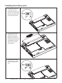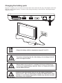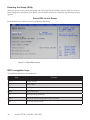
1
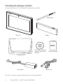
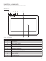
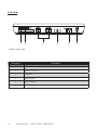
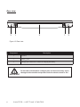
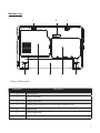
EM-220
User Manual
Copyright
This publication, including all photographs, illustrations and software, is protected under international
copyright laws, with all rights reserved. Neither this manual, nor any of the material contained herein, may be
reproduced without written consent of the author.
Disclaimer
The information in this document is subject to change without notice. The manufacturer makes no
representations or warranties with respect to the contents hereof and specifically disclaims any implied
warranties of merchantability or fitness for any particular purpose. The manufacturer reserves the right to
revise this publication and to make changes from time to time in the content hereof without obligation of the
manufacturer to notify any person of such revision or changes.
Trademark recognition
All product names used in this manual are the properties of their respective owners and are acknowledged.
Federal Communications Commission (FCC)
This equipment has been tested and found to comply with the limits for a Class A digital device, pursuant
to Part 15 of the FCC Rules. These limits are designed to provide reasonable protection against harmful
interference in a residential installation. This equipment generates, uses, and can radiate radio frequency
energy and, if not installed and used in accordance with the instructions, may cause harmful interference
to radio communications. However, there is no guarantee that interference will not occur in a particular
installation. If this equipment does cause harmful interference to radio or television reception, which can be
determined by turning the equipment off and on, the user is encouraged to try to correct the interference by
one or more of the following measures:
Reorient or relocate the receiving antenna.
Increase the separation between the equipment and the receiver.
Connect the equipment onto an outlet on a circuit different from that to which the receiver is connected.
Consult the dealer or an experienced radio/TV technician for help.
Shielded interconnect cables and a shielded AC power cable must be employed with this equipment to
ensure compliance with the pertinent RF emission limits governing this device. Changes or modifications not
expressly approved by the system’s manufacturer could void the user’s authority to operate the equipment.
WARNING
This is a class A product. In a domestic environment this product may
causeradio interference in which case the user may be required to take
adequate measures.
Declaration of conformity
This device complies with part 15 of the FCC rules. Operation is subject to the following conditions:
This device may not cause harmful interference, and
This device must accept any interference received, including interference that may cause undesired operation.
i
About this manual
This manual is intended for system administrators who are familiar with setting up a new system and
installing an operating system.
The manual consists of the following sections:
Chapter 1 Getting Started:
This section covers unpacking and checking the
package contents, identifying components, installing the
battery pack, charging the battery and powering on.
Chapter 2 BIOS Setup Utility: The BIOS chapter provides information on navigating
and changing settings in the BIOS Setup Utility.
Chapter 3 Upgrading Components:This section provides information on upgrading
components.
Appendix: The appendix covers troubleshooting, information
on having the EM-220 serviced, and technical
specifications.
Safety information
Before installing and using the EM-220, take note of the following precautions:
• Read all instructions carefully.
• SAR compliance for body-worn operations is restricted which provide at least 2 cm separation between
the device and the user’s body
• Do not place the unit on an unstable surface, cart, or stand.
• Do not block the slots and opening on the unit, which are provided for ventilation.
• Do not push objects in the ventilation slots as they may touch high voltage components and result in
shock and damage to the components.
• Do not place anything on the power cord. Place the power cord where it will not be in the way of foot
traffic.
• Follow all warnings and cautions in this manual and on the unit case.
• When replacing parts, ensure that your service technician uses parts specified by the manufacturer.
• Avoid using the system near water, in direct sunlight, or near a heating device.
• Never throw the battery into a fire or put it near a fire.
WARNING
Warning! Batteries may explode if not handled properly. Do not disassemble or dispose of them in fire. Keep them away from children. Follow
local regulations when disposing of used batteries.
不正確地更換電池會有爆炸的危險。僅可更換為廠商建議的相同電池或相同型
式電池。請依據廠商說明書棄置電池。
警告
用错误型号电池更换会有爆炸危险务必按照说明处置用完的电池。
注意
ii
TABLE OF CONTENTS
CHAPTER 1 GETTING STARTED������������������������������������������������ 1
Unpacking the machine���������������������������������������������������������������������������������1
Checking the package contents ��������������������������������������������������������������������2
Identifying components ���������������������������������������������������������������������������������3
Installing the battery pack������������������������������������������������������������������������������8
Charging the battery pack������������������������������������������������������������������������������9
Powering on�������������������������������������������������������������������������������������������������10
CHAPTER 2 BIOS SETUP�����������������������������������������������������������11
About the Setup Utility ��������������������������������������������������������������������������������11
Entering the Setup Utility ������������������������������������������������������������������������12
BIOS navigation keys������������������������������������������������������������������������������12
Using BIOS ���������������������������������������������������������������������������������������������13
Main Screen�������������������������������������������������������������������������������������������������14
Advanced Settings���������������������������������������������������������������������������������������15
IDE Configuration������������������������������������������������������������������������������������16
General ACPI Configuration��������������������������������������������������������������������17
USB Configuration�����������������������������������������������������������������������������������18
Boot Settings������������������������������������������������������������������������������������������������19
Boot Settings Configuration���������������������������������������������������������������������20
Boot Device Priority���������������������������������������������������������������������������������21
Hard Disk Drives��������������������������������������������������������������������������������������22
Network Drives����������������������������������������������������������������������������������������23
Security Settings������������������������������������������������������������������������������������������24
Chipset Settings�������������������������������������������������������������������������������������������25
North Bridge Chipset Configuration���������������������������������������������������������26
Exit Menu�����������������������������������������������������������������������������������������������������27
CHAPTER 3 UPGRADING COMPONENTS������������������������������� 29
Safety and precautions��������������������������������������������������������������������������������29
Before you begin������������������������������������������������������������������������������������������30
Upgrading the hard drive�����������������������������������������������������������������������������31
Upgrading the memory module��������������������������������������������������������������������33
Upgrading the Mini-PCIE card���������������������������������������������������������������������34
APPENDIX���������������������������������������������������������������������������������� 37
Troubleshooting�������������������������������������������������������������������������������������������37
iii
Tips for Troubleshooting�������������������������������������������������������������������������������37
General Problems ���������������������������������������������������������������������������������������38
Having the EM-220 Serviced ����������������������������������������������������������������������39
Specification�������������������������������������������������������������������������������������������������40
Revision history
Version 1.0, August 2011
iv
CHAPTER 1
GETTING STARTED
This chapter describes the procedures from unpacking the EM-220, to powering it on. The following topics
are described.
• Unpacking the machine on page 1
• Checking the package contents on page 2
• Identifying components on page 3
• Installing the battery pack on page 8
• Charging the battery pack on page 9
• “Powering on” on page 10
Unpacking the machine
The machine and cable accessories are packed in a cardboard carton with foam padding for protection during
shipping.
Figure 1.1 Unpacking the
machine
Carefully unpack the machine and keep the packing materials. If you need to ship it in the future, repack it as
shown in Figure 1.1.
1
Checking the package contents
After you unpack the device, check that the following items are included.
Metal Stylus
EM-220
Battery
QSG
Driver CD with drivers
and the user manual
PDF file.
Quick Start Guide
Protection pack
AC adapter
If any item is missing or appears damaged, contact your dealer immediately.
2
C H A P T E R 1 G E T T I N G S TA R T E D
Power cord
Identifying components
This section describes the parts and connectors on the machine.
Front view
1
2
3
4 5
6
Figure 1.2 Front view
Component
7
8
9
Description
1
Power indicator
2
Battery charging indicator
3
HDD status indicator
4
WiFi On/ Off indicator
5
Bluetooth On/ Off indicator
6
3.5G LAN On/Off indicator (optional)
7
Built-in Microphone
8
Camera (optional)
9
10.1-inch touch panel
3
Left view
1
2
3
4
Figure 1.3 Left view
Component
4
Description
1
5-in-1 media card slot
2
Express card slot
3
USB port
4
Power button
5
RJ45 LAN jack
6
DC IN
C H A P T E R 1 G E T T I N G S TA R T E D
5
6
Right view
1
2
3
4
5
Figure 1.4 Right view
Component
Description
1
VGA port
2
Ventilation hole
3
USB port
4
Headphone jack
5
Microphone jack
5
Rear view
3
1
2
1
3
Figure 1.5 Rear view
Component
Description
1
Speaker
2
Battery pack
3
Charger pin: connect to a cradle for charging the battery.
Do not short-circuit these 2 charger pins. A short-circuit may cause
damage to the machine and present risks for electric shock or fire.
IMPORTANT
6
C H A P T E R 1 G E T T I N G S TA R T E D
Bottom view
2
1
3
4
5
1
6
7
Figure 1.6 Bottom view
Component
Description
1
Mounting hole
2
Camera (optional)
3
Battery lock switch
4
Memory, WiFi module and 3.5G LAN module (optional) slots
5
Battery pack
6
HDD compartment
7
Battery release latch
7
Installing the battery pack
1. Overturn the EM-220
so that the bottom is
facing up toward you, as
shown in the right. Slide
the battery release latch
to the unlock position.
2. Align EM-220 battery
compartment pins to
the battery connector.
Slightly slide and press
the battery pack into the
compartment until the
battery lock switch is
bounced back.
3. As shown in the right,
slide the battery release
latch to the lock position.
8
C H A P T E R 1 G E T T I N G S TA R T E D
Charging the battery pack
Plug the AC adapter power cord into an electrical outlet, then connect the DC plug of the adapter cable to the
EM-220. It takes approximately 2–4 hours to fully charge the battery for the first time. Subsequent charges
might take longer.
Charge the battery within a temperature range 0˚C to 45˚C.
NOTE
To protect and prolong the life of the battery, do not charge it for 24
hours or longer at a time.
IMPORTANT
IMPORTANT
Please make sure to perform 3 complete full charge and discharge
cycles to get optimal battery capacity. Failure to comply will result in
shorter battery lifespan.
If battery is not used, please store in dry area within a temperature
range of -10˚C ~ 20˚C. It is necessary to charge the battery once every
3 months to avoid battery degradation. Battery may become unusable
IMPORTANT if the above is not respected.
9
Powering on
The power button located on the left side of the EM-220, press the power button the turn it on.
To force power off , long press the power button for 4~5 seconds.
NOTE
10
C H A P T E R 1 G E T T I N G S TA R T E D
CHAPTER 2
BIOS SETUP
The primary function of the BIOS (Basic Input and Output System) is to identify and initiate component
hardware. The BIOS parameters are stored in non-volatile BIOS memory (CMOS). CMOS contents don’t get
erased when the computer is turned off. The following topics are described in this chapter.
•
•
•
•
•
•
•
About the Setup Utility on page 11
Main Screen on page 14
Advanced Settings on page 15
Boot Settings on page 19
Security Settings on page 24
Chipset Settings on page 25
Exit Menu on page 27
About the Setup Utility
The BIOS Setup Utility enables you to configure the following items:
•
Hard drives, diskette drives, and peripherals
•
Video display type and display options
•
Password protection from unauthorized use
•
Power management features
This Setup Utility should be used for the following:
•
When changing the system configuration
•
When a configuration error is detected and you are prompted to make changes to the Setup Utility
•
When trying to resolve IRQ conflicts
•
When making changes to the Power Management configuration
•
When changing the User or Supervisor password
11
Entering the Setup Utility
When you power on the system, BIOS enters the Power-On Self Test (POST) routines. POST is a series of
built-in diagnostics performed by the BIOS. After the POST routines are completed, the following message
appears:
Press DEL to run Setup
Press the delete key <Delete> to access the BIOS Setup Utility:
Figure 2.1 Main BIOS screen
BIOS navigation keys
The BIOS navigation keys are listed below.
Key
Function
←→
Select screens
↑↓
Select items
+–
Modifies the selected field’s values
Enter
Go to sub screen
F1
Displays the general help
F10
Saves the current configuration and exits Setup Esc
Exits the current screen
12
CHAPTER 2 BIOS SETUP
Using BIOS
When you start the Setup Utility, the main screen appears. The main screen of the Setup Utility displays a list
of the options that are available. A highlight indicates which option is currently selected. Use the cursor arrow
keys to move the highlight to other options. When an option is highlighted, execute the option by pressing
<Enter>.
Some options lead to pop-up dialog boxes that prompt you to verify that you wish to execute that option.
Other options lead to dialog boxes that prompt you for information.
Some options (marked with a triangle ►) lead to sub screens that enable you to change the values for the
option. Use the cursor arrow keys to scroll through the items in the sub screen.
13
Main Screen
This screen includes System BIOS Information, Processor, System memory and displays the System Time
and System Date.
Figure 2.2 Main Screen
System Overview
This screen displays System BIOS Information, Processor, System memory, System Time and System Date.
System Time/ System Date
The System Time and System Date items show the current date and time held by the machine. If you are
running a Windows OS, these items are automatically updated whenever you make changes to the Windows
Time and Date Properties utility.
14
CHAPTER 2 BIOS SETUP
Advanced Settings
This setup screen includes sub-menus for IDE Configuration, USB Configuration, ACPI Configurations, MPS
Configurations, Super IO Configurations and Hardware Health Configuration.
Figure 2.3 Advanced Settings Screen
ALL ON/ALL OFF/Customize
This item allows users to on/off expansion modules.
[All On] Enable BT, WLAN, WWAN, G Sensor, Front Camera and Rear Camera.
[All Off] Disable BT, WLAN, WWAN, G Sensor, Front Camera and Rear Camera.
[Customize] Set each module separately.
Touch Panel
This feature allows users to select the type for touch panel.
15
IDE Configuration
Figure 2.4 IDE Configuration sub-menu
ATA/IDE Configuration
This item allows users to specific the integrated IDE controller.
[Disabled] disables the integrated IDE controller.
[Compatible] enables up to two IDE channels for operating systems requiring legacy IDE operation.
[Enhanced] enables all SATA and PATA resources.
16
CHAPTER 2 BIOS SETUP
General ACPI Configuration
Figure 2.5 General ACPI Configuration sub-menu
Suspend mode
Use this item to define how the system suspends. In the default, S1(POS), the suspend mode is equivalent to a
software power down. If you select S3(STR), the suspend mode is a suspend to RAM - the system shuts down
with the exception of a refresh current to the system memory.
Wake-On-Lan (WOL)
This feature allows the system to be woken up by a network message.
17
USB Configuration
Figure 2.6 USB Configuration sub-menu
USB 2.0 Controller Mode
This item allows you to specific the USB 2.0 controller in HiSpeed (480Mbps) or Full Speed (12Mbps).
18
CHAPTER 2 BIOS SETUP
Boot Settings
This screen allow you to configure the boot options.
Figure 2.7 Boot Settings screen
19
Boot Settings Configuration
Figure 2.8 Boot Settings Configuration sub-menu
Quick Boot
Enabling this setting will cause the BIOS power-on self test routine to skip some of its tests during booting
for faster system boot.
Quiet Boot
When enabled, system will boot without message. In contrast, when disabled, system will boot in text mode.
Bootup Num-Lock
This setting is to set the Num Lock status when the system is powered on. Setting to [On] will turn on the
Num Lock key when the system is powered on. Setting to [Off] will allow users to use the arrow keys on the
numeric keypad.
20
CHAPTER 2 BIOS SETUP
Boot Device Priority
Use this screen to specify the order in which the system checks for the device to boot from.
Figure 2.9 Boot Device Priority sub-menu
1st Boot Device
2nd Boot Device
Set the boot device options to determine the sequence in which the computer checks which device to boot
from.
21
Hard Disk Drives
Use this screen to specify the boot sequence from hard disk drives.
Figure 2.10 Hard Disk Drives sub-menu
1st Drive
Use this item to view the hard disk drives in the system.
22
CHAPTER 2 BIOS SETUP
Network Drives
Use this screen to specify the boot sequence from network drives.
Figure 2.11 Network Drives sub-menu
1st Drive
Use this item to view the network drives in the system.
23
Security Settings
This screen allows you to configure the system security settings.
Figure 2.12 Security Settings screen
Supervisor/ User Password
Indicates whether a password has been set. If the password has been installed, Installed displays. If not, Not
Installed displays.
Set Supervisor Password
This item is used to establish password protection when entering the BIOS setup.
Set User Password
This item is used to establish password protection when entering the BIOS setup but some menu items will be
unavailable. A supervisor password must be set before a user password can be used.
Boot Sector Virus Protection
This feature can prevent modifications to the boot sector.
24
CHAPTER 2 BIOS SETUP
Chipset Settings
This screen allow you to configure the North Bridge and South Bridge chipset options.
Figure 2.13 Chipset Settings screen
25
North Bridge Chipset Configuration
Figure 2.14 North Bridge Chipset Configuration sub-menu
Internal Graphics Mode Select
This feature controls the amount of system memory that is allocated to the integrated graphic process when
the system boot up.
Boot Display Device
If you connect an external display to this machine, you can use this setting to turn off the LCD and only use
the external display. To use dual displays this must be set to CRT+LVDS.
Flat Panel Type
This item allows you to select the type of Flat Panel Monitor.
LVDS Backlight Control
This feature allows you to adjust the backlight of the LVDS.
26
CHAPTER 2 BIOS SETUP
Exit Menu
This screen allows you to load the optimal default values, and save or discard changes.
Figure 2.15 Exit Menu screen
Exit Saving Changes
Highlight this item and press <Enter> to save the changes that you have made in the Setup Utility and exit the
Setup Utility. When the dialog box appears, press <OK> to save and exit, or press <Cancel> to return to the
menu.
Exit Discarding Changes
Highlight this item and press <Enter> to discard any changes that you have made in the Setup Utility and exit.
When the dialog box appears, press <OK> to discard changes and exit, or press <Cancel> to return to the
menu.
NOTE
If you have made settings that you do not want to save, use the “Exit
Discarding Charges” item and press OK to discard any changes you
have made.
Load Optimal Defaults
This option opens a dialog box that lets you load optimized defaults for all appropriate items in the Setup
Utility. The optimized defaults place demands on the system that may be greater than the performance level
of the components, such as the CPU and the memory. You can cause fatal errors or instability if you load the
optimized defaults when the hardware does not support them. If you only want to load setup defaults for a
specific option, select and display that option, and then press <F9>.
Follow these instructions to load the optimized defaults:
1. From the Exit screen, scroll to Load Optimized Defaults.
2. Press <Enter> to open the Load Optimized Defaults screen.
3. Select <Ok>.
4. Press <Enter> to load the defaults.
27
Discard Changes
Highlight this item and press <Enter> to discard any changes that you have made in the Setup Utility. When
the dialog box appears, press <OK> to discard changes and exit, or press <Cancel> to return to the menu.
28
CHAPTER 2 BIOS SETUP
CHAPTER 3
UPGRADING COMPONENTS
This chapter describes how to upgrade components for the EM-220. The following topics are described.
•
•
•
•
•
Safety and precautions on page 29
Before you begin on page 30
Upgrading the hard drive on page 31
Upgrading the memory module on page 33
Upgrading the Mini-PCIE card on page 34
Safety and precautions
Computer components and electronic circuit boards can be damaged by discharges of static electricity.
Working on computers that are still connected to a power supply can be extremely dangerous. Follow these
guidelines to avoid damage to the computer or injury to yourself.
• Always disconnect the unit from the power outlet.
• Leave all components inside the static-proof packaging that they ship with until they are ready for installation.
• After replacing optional devices, make sure all screws, springs, or other small parts are in place and are
not left loose inside the case. Metallic parts or metal flakes can cause electrical shorts.
Only qualified personnel should perform repairs on the machine.
Damage due to unauthorized servicing is not covered by the warranty.
If you are not confident of installing a hard drive, memory card or LAN
CAUTION card, we recommend that you refer the job to qualified personnel.
If the LCD breaks and fluid gets onto your hands or into your eyes,
immediately wash with water and seek medical attention.
WARNING
WARNING
The inverter card has high voltage. Do not touch the inverter card while
power is connected to the machine. Unplug the power cord before
attempting to replace any part.
To prevent static damage to components, wear a grounded wrist strap.
Alternatively, discharge any static electricity by touching the bare metal
chassis of the unit case, or the bare metal body of any other grounded
CAUTION appliance.
Hold electronic circuit boards by the edges only. Do not touch the
components on the board unless it is necessary to do so. Do not flex or
stress the circuit board. Do not hold components such as a processor
CAUTION by its pins; hold it by the edges.
29
Before you begin
Make sure you have a stable, clean working environment. Dust and dirt can get into components and may
cause malfunction. Adequate lighting and proper tools can prevent you from accidentally damaging the
internal components.
Most of the electrical and mechanical connections can be disconnected by using your fingers. It is
recommended that you do not use needle-nosed pliers to disconnect connectors as these can damage the soft
metal or plastic parts of the connectors.
CAUTION
30
To prevent scratching the case of the machine, make sure the worktop
surface is clean and flat.
CHAPTER 3 UPGRADING COMPONENTS
Upgrading the hard drive
Refer to the following to remove and replace the hard drive.
1. Turn off the EM-220.
2. Disconnect the AC adapter
cable.
3. Overturn the EM-220.
4. Remove the two screws as
shown in the right.
5. Open and remove the hard drive
compartment cover.
6. Slide the hard drive to
disconnect.
31
7. Remove the hard drive.
8. Remove the four screws, then
remove the hard drive out from
the tray.
To replace the hard drive, reverse the above procedure.
32
CHAPTER 3 UPGRADING COMPONENTS
Upgrading the memory module
Refer to the following to remove and replace the memory.
1. Turn off the EM-220.
2. Disconnect the AC adapter
cable.
3. Overturn the EM-220.
4. Remove the two screws as
shown in the right.
5. Open and remove the memory
module compartment cover.
6. Locate the memory module, as
shown in the right.
33
7. Pop out the two silver latches
holding the memory module
into place. The module pops
up. Grasp the outer edges of the
memory module with thumb
and forefinger, and then gently
remove it.
To replace the memory module, reverse the above procedure.
Upgrading the Mini-PCIE card
Refer to the following to remove and replace the PCIE card.
1. Turn off the EM-220.
2. Disconnect the AC adapter
cable.
3. Overturn the EM-220.
4. Remove the two screws as
shown in the right.
5. Open and remove the MiniPCIE card compartment cover.
34
CHAPTER 3 UPGRADING COMPONENTS
6. Locate the Mini-PCIE card, as
shown in the right.
7. Remove the screw on the MiniPCIE card, Mini-PCIE will pop
up 45 degree.
8. When it pops up, gently remove
it.
To replace the Mini-PCIE card, reverse the above procedure.
35
36
CHAPTER 3 UPGRADING COMPONENTS
APPENDIX
This appendix describes locating and solving problems that you may encounter while using the EM-220.
Troubleshooting
Often after time spent troubleshooting, the problem is traced to something as simple as a loose connection.
Check the following before proceeding to the problem-specific solutions.
Tips for Troubleshooting
In each problem-specific section, try the steps in the order suggested. This may help you to solve the problem
more quickly. Try to pin point the problem and thus avoid replacing non-defective parts. For example, if you
replace batteries and the problem remains, put the original batteries back and go to the next step.
Keep a record of the steps you take when troubleshooting: The information may be useful when calling for
technical support or for passing on to service personnel.
•
Use some other electrical device to confirm that the electrical outlet is working.
•
Ensure all connections are securely attached.
37
General Problems
Refer to the following general problems you may encounter.
PROBLEM
SOLUTION
The display screen is dark.
Make sure that the EM-220 is not in suspend
mode.
An incorrect date and time are displayed.
Set the date and time in BIOS or Operation
System.
Cannot be turned off after crash.
Long press the power button for 4 seconds to force
shutdown.
Cannot be powered on
Connect the AC adapter, if it can be powered on,
there is insufficient battery power. If it still unable
to be powered on after charging, please have the
EM-220 serviced.
38
APPENDIX
Having the EM-220 Serviced
If you are unable to solve the problem, you should have the terminal serviced. Pack the terminal in the
original carton. (See “Unpacking the EM-220” on page 1.) Include a description of the problem and a
checklist of the steps you took when trying to fix the problem. The information may be useful to the service
personnel. Return the terminal to the place you purchased it.
39
Specification
Processor
Intel® ATOM N455 1.66GHz
LCD
10.1” Active TFT color LCD, resolution 1024 x 600, or 1366 x768(option)
Touch
4-wire Resistive touch
Memory
DDR3 1GB Standard, Maximum 2 GB (1 x DDR3 SO-DIMM Slots)
Ethernet
On board LAN chip 10/100/1000 BASE-T Gigabit Ethernet
Storage
2.5” type SATA HDD
1 * DB-15 VGA port
1 * RJ-45 LAN port
2 * Audio ports (1 * Line-out , 1 * MIC-in)
I/O Interface
3 * USB 2.0
1 * 5 in 1 card reader slot, support SD,MMC,MS,MS pro , XD
1 * express34 slot
1* SIMM slot
Expansion Options
2 * Mini PCI-e, Support wireless LAN and 3G Module(option)
Battery life
3 hours (estimated)
Operation System
Windows 7, Windows XP, XPe, Linux (ubuntu, Fedora) , WEPOS, POSReady
POS Base
Optional
Peripherals
Charging Base
EM-220 Jacket with MSR , RFID or Barcode scanner modules (1D or 2D)
VESA mount (75x75mm, 100x100mm)
Power Supply
AC100~240V/DC12V, 36 watt power adaptor
Dimensions
Physical:189mm (W) x268mm (H) x 25.7mm (T)
Weight
Appox.1160g
Operating Temp
* specification subject to change without prior notice
40
APPENDIX
0°C ~ +40°C