1
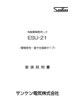
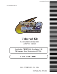
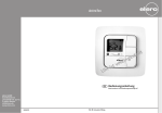
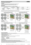
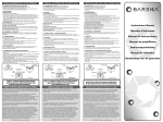
UFO®micro-Steckdose
UFO®micro socket
Prise UFO ®micro
Die UFO®micro-Steckdose ESU 32 ist speziell für den Einsatz in Verbindung mit
der Einkabel-Matrix EXU 544 entwickelt worden
Gleichspannungsdurchlässiger Sat-Anschluss (max. 24 VDC)
Abschaltfunktion für die Spannung bei Überlast (typ. 85 mA)
Hinweis: Zurücksetzung der Abschaltung durch kurzzeitige Abschaltung der LNBSpannung am Receiver.
Die Steckdose ESU 32 stimmt mit den zum Zeitpunkt der Auslieferung gültigen
Anforderungen der Richtlinie 73/23 EWG und 89/336/EWG überein
Weitere Hinweise zur Steckdose ESU 32 finden Sie im Anwendungshinweis der
Einkabel-Matrix EXU 544
Selektive Anschlüsse für TV, FM und Sat-ZF
The UFO®micro socket ESU 32 has been designed for use in connection with the single
cable matrix EXU 544
Sat connection point allows DC feed-through (max. 24 V DC)
The feed-through tension will be switched off in case of surcharge
(typ. 85 mA). Note: The disconnection is cancelled if the LNB current is shortly
interrupted on the receiver
The socket ESU 32 complies with the requirements of the guidelines EEC 73/23 and
EEC 89/336
More information about the socket ESU 31 is found in the user guides for the single
cable matrix EXU 544
Selective connections for TV, FM and Sat IF
La prise UFO®micro ESU 32 est destinée à être utilisée conjointement avec la matrice
EXU 544.
Connecteur FI satellite permet le passage de la tension DC (max. de 24 V DC).
La tension de téléalimentation est coupée s’il y a de surtension (typ. 85 mA)
Remarque: La téléalimentation est restituée après une bréve coupure de
l’alimentation LNB au récepteur.
La prise ESU 32 répond aux prescriptions 73/23 CEE et CEE 89/336
Plus d’information sur la prise ESU 32 peut être enlevée de la notice pour la matrice
EXU 544
Connecteur sélectif pour TV, FM et BIS
ESU 32
21110005
TV
47–68/118–862 MHz
FM
87–108 MHz
Sat-ZF + DC
+ DiSEqC
950–2150 MHz
Montagefreundlich durch:
– unverlierbare, aufklappbare Kabelschelle – kurzschlusssichere Kabelklemmen – Für AP- und UP-Montage, mit Schraub- oder Krallenbefestigung Für Gerätedosen mit einem Innendurchmesser
von 55 bis 65 mm.
Anschlüsse nach IEC 169-2 und IEC 169-24.
Installation friendly thanks to:
– hinged cable clamp that cannot be lost – short-circuit proof clamp connections for surface
and flush-mounting with screw and claw-fixing For 55 – 65 mm Ø insulation boxes
Connections acc. to Standard IEC 169-2 and
IEC 169-24
Facile à monter grâce à:
– clapet de câble rebattable, imperdable – montage sous crépi ou en saillie par vis ou à griffes Pour des boîtiers isolants de 55 – 65 mm Ø.
Raccordement selon Standard IEC 169-2 et
IEC 169-24
Achtung! Die Steckdose ESU 32 ist ausschließlich für das folgende Anlagen-System
zu verwenden:
In Verbindung mit der Einkabel-Matrix EXU 544 und UFO® micro-Mode tauglichen
Receivern. Es soll in einem Systemabschnitt nur die ESU 32 eingesetzt werden
(nicht mit ESU 31, BN 274436, mischen)
Attention! The socket ESU 32 is exclusively designed for the following system:
Used in conjunction with the single-cable matrix EXU 544 and UFO® micro mode compatible receivers. Only the ESU 32 should be used in one
system segment (not to be mixed up with ESU 31, order no. 274436).
Attention! La prise ESU 32 doit être utilisée uniquement en combinaison avec les système de réception mentionnés ci-dessous:
Pour systèmes avec la matrice monocâble EXU 544 et des récepteurs UFO® micro compatibles. Montez dans un secteur du système seulemente
des prises ESU 32 (ne mêlez pas avec ESU 31, Réf. 274436)
Technische Daten / Technical Data / Données techniques
Übertragungsbereich
Frequency ranges
Gammes de fréquences
FM
MHz
dB
1,0
dB
11,0
dB
10,0
470–862
Sat-ZF
Sat-IF
FI Sat
950–2150
1,1
2,0
10,0
10,0
47– 300 MHz ≥ 85, 300– 470 MHz ≥ 80, 470–862 MHz ≥ 75, 950–2 150 MHz ≥ 55
dB
) Damit die angegebenen Werte erreicht werden,
müssen nicht genutzte Ausgänge mit Abschlusswiderständen oder Kappen schirmdicht
verschlossen werden.
1
87–108
UHF
Max. 24 V DC + 22 kHz + DiSEqC/max. 80 mA
Abschaltung der Spannung vom Sat-Anschluss zum Stamm durch Erkennung einer Überlast von typ. 85 mA
Remote power feeding is cut off in case a surcharge of typ. 85 mA occurs
La tension de téléalimentation est coupée s’il y a de surtension de 85 mA typique
) In order to ensure that the given values are adhered
to, all unused outputs must be closed with a
terminating resistor or with a cap.
1
) Il faut fermer les sorties non-utilisées avec une
charge afin que les valeurs de blindage soient
respectées.
1
936.2438/0803/1.2def
Durchgangsdämpfung/Through loss
Affaiblissement de passage
Anschlussdämpfung/Tap loss
Affaiblissement de raccordement
Schirmungsmaß1)
Screening factor1)/
Facteur de blindage1)
Fernspeisung
Remote power feeding
Téléalimentation
BI/USB/BIII/OSB/ESB
BI/MSB/BIII/SB/ESB
BI/IBH/BIII/IBB/HYB
47–68/118–470
Anlagenbeispiel
Installation example
Exemple d’utilisation
UAS 484
4 x Sat-ZF, 12 Teilnehmer
4 x Sat IF, 12 subscribers
4 x IF Sat, 12 abonnés
EBC 02
STATUS
1/18 V = 0,40 A
1/18 V = 0,40 A
2/14 V = 30 mA
2/14 V = 30 mA
3/14 V = 30 mA
3/14 V = 30 mA
3/14 V = 30 mA
4/18 V = 0,40 A
Terr.
ESUESU
32 31
ERA 14
4/18 V = 0,40 A
4/18 V = 0,40 A
EXU 544
ERA 14
STATUS
STATUS
1/18 V = 0,40 A
2/14 V = 30 mA
Select
EXU 544
Terr.
Select
EXU 544
Terr.
Copy
Copy
Copy
Out
Out
Out
EBC 20
Select
ESU 31
32
ESU
Montagehinweise:
– Installation durch Fachpersonal
– Einsatz nur in trockenen Innenräumen
– Montagewerkzeug:
– Messer oder Abisolierhilfe
– Kreuzschlitzschraubendreher Gr. 1
oder Schlitzschraubendreher 5 x 0,8.
– Außenleiter beim Abisolieren nicht
beschädigen, weil sonst die angegebenen
Schirmungsmaße nicht erreicht werden
– Geflechtadern dürfen nach dem Anklemmen
des Kabels wegen Kurzschlussgefahr den
Innenleiter nicht berühren.
– Vorsicht vor Krallenspitzen: Verletzungsgefahr!
Montage / Mounting / Montage
1. Kabel abisolieren
1. Baring the cable
1. Elèvement de l’isolation
80mm
15
Installation advice:
– Only by qualified technicians
– Only indoor in dry places
– Mounting tools:
– Knife or stripping aid
– Philips screwdriver size 1 or standard
screwdriver 5 x 0.8
– Do not damage the outer conductor
when baring screening factor cannot be
attained)
– After the connection of the cable, make
sure that no wires of the outer conductor
touch the interior conductor, otherwise a
short-circuit may occur
– Do not touch the tips of the claws.
Danger of injury.
2. Kabel anklemmen:
– Klappe öffnen
– Innenleiter anklemmen
– Klappe schließen, Schraube anziehen
2.
the cable:
2. Connect
Kabel anklemmen:
– open the flap
– connect the centre conductor
– close the flap, tighten the screw
Conseils de montage:
– Installation seulement par des techniciens
spécialisés
– Installation seulement à l’intérieur en endroits
secs.
– Outils de montage:
– Couteau ou aide de dégainement
– Tournevis Philips No. 1 ou tournevis plat 5 x 0,8
– N’endommagez pas la tresse extérieure
lors du dégainement (le facteur de blindage
sera mis en cause)
– Lors du branchement du câble, veillez à ce
qu’aucun fil de la tresse ne touche le conducteur
intérieur (court-circuit)
– Ne touchz pas les pointes des griffes
(Danger de blessure)
3. Dose mit Kabel um 180°
drehen.
3. Turn socket with cable by
180°.
3. Tourner prise avec câble
par 180°.
5
Ø
mm
4,1-7mm
¯ 4,1–7
2.
Raccorder
le câble:
- Klappe
ˆffnen
– Ouvrir le klemmen
clapet
- Innenleiter
– Raccorder
le conducteur intérieur
- Klappe
schlieflen,
– Fermer le clapet, serrer la vis
Schraube anziehen
4. Steckdose in Gerätedose
drücken und festklemmen.
4. Place socket into insulation box
and fix it
4. Placer prise dans le boitier et fixer
KATHREIN-Werke KG · Anton-Kathrein-Straße 1–3 · Postfach 10 04 44 · D-83004 Rosenheim · Deutschland · Telefon (0 80 31) 18 40 · Telefax (0 80 31) 18 43 06
Subject to technical changes.
Anschlussmöglichkeiten an der ESU 32
Connection possibilities for ESU 32
Possibilités de raccordement ESU 32
936.2438/0803/2.2def/SKS Technische Änderungen vorbehalten.
Hinweis:
– Nur UFO®micro-Mode-taugliche Receiver verwenden
– Die letzte Steckdose im Stamm ist immer mit einem Abschlusswiderstand mit kapazitiver Trennung (ERA 14) abzuschließen
– Nur UFO®micro-Steckdosen ESU 32 in einem System-Abschnitt verwenden. Nicht mit ESU 31 (BN 274436) mischen
Note:
– Use UFO®micro mode compatible receivers only.
– Terminate the last socket in a line with terminating capacitive resistor (ERA 14)
– Only use UFO®micro compatible sockets ESU 32 in a system segment. Do not mix with ESU 31, order no. 274436.
Remarque:
– N’utilisez que des récepteurs satellite compatibles avec UFO®micro.
– Fermez toujours la dernière prise de ligne avec une charge capacitive (ERA 14).
– Utilisez seulement des prises ESU 32. Ne pas mélanger avec ESU 31, Réf. 274436.
Nous nous réservons le droit de toutes modifications techniques.
ERA 14