1
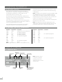
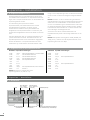
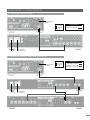
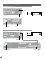
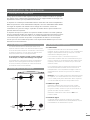
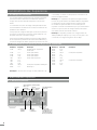
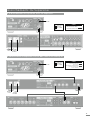
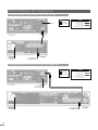
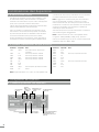
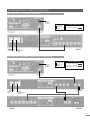
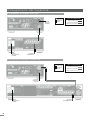
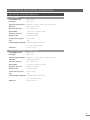
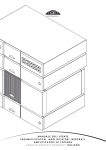
OWNERS MANUAL
SuperLine
ENGLISH DEUTSCH FRANÇAIS ITALIAN0
I ntrod u c tio n
Naim Audio products are conceived with performance as the top priority. Careful
installation will help ensure that their full potential is achieved. This manual covers
the SuperLine phono amplifier. It begins with some general installation notes. Product
specific information begins in Section 3.
1 Con n ect ions
It is important for both safety and performance that
any standard cables supplied with Naim Audio
products are not modified.
1. 1 Interconne c t C able s
Interconnect plugs and sockets should be kept clean
and free from corrosion. The easiest way to clean them
is to switch off the equipment, pull the plugs out of their
sockets, and push them back in again. Contact cleaners
and “enhancers” should not be used as the film they
deposit may degrade the sound.
2 Gen er al Instal l a ti o n
Naim equipment is designed to offer the finest
performance possible avoiding compromise
wherever practical. This can lead to circumstances
that may be unfamiliar. The notes that follow contain
advice specifically related to Naim equipment as
well as more general warnings about the use of
domestic audio products. Please read them carefully.
2. 1 S iting The Equipme nt
In order to reduce the risk of hum audible from the
loudspeakers, power supplies and power amplifiers
should be located a reasonable distance away from
other equipment. The maximum separation distance for
connected equipment is that allowed by the standard
interconnect lead.
2. 2 S witching O n
Source components and power supplies should be
switched on before power amplifiers. Always switch
amplifiers off and wait a minute before connecting or
disconnecting any leads. Always use the power switch on
the product rather than a mains outlet switch.
2. 3 Running In
Naim equipment takes a considerable time to run in
before it performs at its best. The duration varies, but under
some conditions the sound may continue to improve for
over a month. Better and more consistent performance
will be achieved if the system is left switched on for long
periods. It is worth remembering however that equipment
left connected to the mains can be damaged by
lightning.
2 . 4 R a d i o I n t er f er en ce
In some circumstances, depending on where you live
and the earthing arrangements in your home, you may
experience radio frequency interference. Controls on
broadcasting in some territories allow very high levels of
radio frequency radiation and both the choice and exact
siting of equipment may be critical. Susceptibility to radio
frequency interference is related to the wide internal
bandwidth necessary for high sound quality. A radio
frequency filter kit is available for some Naim equipment
but sound quality will be progressively compromised as
more elements of the kit are fitted. In situations of extreme
radio interference Naim equipment may be unsuitable.
2 . 5 L i g h t n i n g P r eca u t i on s
Your Naim hi-fi system can be damaged by lightning and
should be turned off and disconnected from the mains
when there is risk of lightning strike.
2 . 6 P r ob l em s ?
Consumer protection varies from country to country. In
most territories a retailer must be prepared to take back
any equipment he has sold if it cannot be made to work
satisfactorily. A problem may be due to a fault in the
system or its installation so it is essential to make full use of
your dealer’s diagnostic skills. Please contact your local
distributor, or Naim Audio directly, if any difficulties cannot
be resolved.
Some Naim equipment is made in special versions for
different territories and this makes it impracticable to
arrange international guarantees. Please establish the
local guarantee arrangements with your retailer. Contact
Naim Audio directly for help and advice if necessary.
2 . 7 S er v i ce a n d Up d a t es
It is essential that repairs and updates are only carried
out by an authorised Naim retailer or at the factory by
Naim itself. Many components are custom made, tested
or matched and appropriate replacements are often
unobtainable from other sources.
Direct contact to Naim for service or update information
should be made initially through Customer Services:
Tel: Email:
+44 (0)1722 426600
[email protected]
Please quote the product serial number (found on its rear
panel) in all correspondence.
Su p e rL ine Insta lla tio n
3 Su per Lin e Instal l a ti o n
The SuperLine moving coil phono amplifier is designed to extract the best possible musical
performance from vinyl disc replay. It should be mounted horizontally on an equipment
stand intended for the purpose. It is important to ensure that it is level.
The SuperLine contains no internal power supply and must be connected either to a Naim
amplifier incorporating an appropriate power supply output, or to a dedicated Naim
power supply. SuperLine output is muted for 2 minutes following switch-on to allow its
circuitry to reach optimal status.
Cartridge loading resistance and capacitance can be adjusted by inserting combinations
of resistive and capacitive “load plugs” into sockets on the SuperLine rear panel.
The SuperLine incorporates a suspension system to isolate its sensitive components from
vibrational energy. The suspension system is protected during shipping by two transit
screws. The transit screws must be removed before use. Once the transit screws are
removed the SuperLine must not be inverted. Transit screw removal is best carried out
once the SuperLine is installed in its final location and all connections are made.
3. 1 Transit S c re ws
Two transit screws must be removed from the underside of
the SuperLine before use and replaced if it is to be carried
any distance, packed or shipped. Transit screw removal is
illustrated in Diagram 3.2. SuperLine transit screws must not
be used with any other Naim product.
Damage may result if the SuperLine is inverted either
during or after transit screw removal.
To gain access to the transit screws, position one end
of the SuperLine over the edge of a table, remove (or
replace) the screw that becomes accessible and then
repeat with the other end.
3. 2 Transit S c re w Re mo v al
front transit
screw
3 . 3 C on n ect i n g S u p er L i n e
3.3.1 Power Supply
The SuperLine must be connected to a dedicated
Supercap, Hi-Cap or Flatcap power supply (option
one) or a Naim preamplifier or integrated amplifier that
incorporates an appropriate power supply output (option
two).
If option one is chosen, connect the SuperLine to the
dedicated power supply using, in the case of a Hi-Cap
or Flatcap, a Naim SNAIC interconnect cable, and in the
case of a Supercap, the appropriate Naim Burndy cable.
In either case take care to connect with the correct cable
orientation.
If option two is chosen, connect the SuperLine to the
preamplifier or integrated amplifier’s 5 pin DIN aux input/
power output socket using a Naim SNAIC interconnect
cable. Take care to connect with the correct cable
orientation.
Note: If the SuperLine’s Burndy power supply socket is
not used the supplied Burndy link plug must be inserted.
Similarly, if the SuperLine’s DIN power supply socket is not
used the supplied dust cover should be fitted.
3.3.2 Signal Input
Connect the output cable of the pick-up arm to either
the BNC or phono input sockets. Only one option, phono
or BNC, should be connected at any time. Take care to
ensure that the left and right channels are connected to
the appropriate sockets.
Connect the pick-up arm earth lead to the rear panel
ground terminal.
3.3.3 Signal Output
rear transit
screw
The SuperLine output signal is carried on the power supply
cable either directly to the preamplifier or via an optional
power supply.
1
Su p e rL ine Insta lla tio n
3. 4 Cartridge Lo ading
The resistive and capacitive input load presented by
the SuperLine to the pick-up cartridge can be adjusted
by inserting a combination of “load plugs” into the
appropriate sockets in the rear panel.
The appropriate load plug combination will depend on
both the manufacturer’s recommendations for the pick-up
cartridge in use and subjective preference.
Each load plug is constructed from a 5-pin DIN plug that
contains the appropriate passive components. A label on
each load plug identifies its load value.
Seven standard load plugs are supplied - four resistive
and three capacitive - to provide 20 combinations
(including the default input loads applied when no load
plugs are inserted). Table 3.5 lists the standard load plug
combinations.
Note: In addition to the standard load plugs supplied, 470Ω
and 560Ω resistive plugs are also available on request.
Other values may also be created either by modifying
standard plugs or manufacturing new ones. Contact your
retailer or local distributor for more information.
Always ensure that resistive and capacitive load plugs are
inserted in the correct socket.
Note: The SuperLine incorporates 10kΩ resistance and
100pF (0.1nF) capacitance loads internally. With no load
plugs fitted these values constitute the default load.
3. 5 Cartridge Lo ad P lug C o mbinati on s
Resistance
Capacitance Comments
Resistance
Capacitance Comments
10kΩ
100pF Internal load only. No plugs fitted.
500Ω
4.7nF
10kΩ
10kΩ
10kΩ
1kΩ
1kΩ
1kΩ
1kΩ
500Ω
500Ω
1nF 4.7nF 10nF 100pF 1nF
4.7nF
10nF
100pF 1nF No resistive plug fitted.
No resistive plug fitted.
No resistive plug fitted.
No capacitive plug fitted.
500Ω
220Ω
220Ω
220Ω
220Ω
100Ω
100Ω
100Ω
100Ω
10nF
100pF
1nF
4.7nF
10nF
100pF 1nF
4.7nF
10nF
No capacitive plug fitted.
Note 1
Note 1: Approximates to a Naim ‘K’ load (560Ω and 1nF).
4 Su per Lin e Connecti o ns
4. 1 S uperLine Re ar
pick-up arm
ground
BNC input
sockets. Ch. phono input
1 - left, Ch. 2 sockets. Ch. 1
- left, Ch. 2 - right
- right
to Supercap
power supply
Note: SuperLine output
is muted for 2 minutes
following switch-on to
allow its circuitry to reach
optimal status.
resistive
load plug
socket
2
capacitive
load plug
socket
to amplifier power
supply output or to
Hi-Cap or Flatcap
power supply
No capacitive plug fitted.
No capacitive plug fitted.
Su p e rL ine Co nnec tio ns
4. 2 S uperLine c o nne c te d to Supe rn a i t
link plug
fitted
cable
direction
marker
Interconnect Cables
240° 5 to 5 pin DIN
power
mains
input
and fuse
4. 3 S uperLine c o nne c te d to NAC 1 2 2 x a n d Fl a t ca p 2 x
link plug
fitted
power
cable
direction
marker
Interconnect Cables
240° 5 to 5 pin DIN
4 pin to 5 pin DIN
(or 4 to 5 pin Hi-Line)
mains
input
and fuse
3
Su p e rL ine C o nnec tio ns
4. 4 S uperLine c o nne c te d to H i- C ap
link plug
fitted
mains input
and fuse
cable
direction
marker
Interconnect Cables
240° 5 to 5 pin DIN
4 pin to 5 pin DIN
(or 4 to 5 pin Hi-Line)
to preamplifier
input
4. 5 S uperLine c o nne c te d to Supe rca p
cable
direction
marker
Interconnect Cables
SuperLine Burndy
4 pin to 5 pin DIN
(or 4 to 5 pin Hi-Line)
dust cover
fitted
mains input
and fuse
4
to preamplifier
input
Su p e rL ine Sp ec if ic a ti ons
5 Su per Lin e Speci fi ca ti o n
5. 1 S tandard M o de l
Cartridge compatibility
100µV to 500µV
Gain 64dB @ 1kHz
Signal to Noise
82dB ref 500µV input, 0 Ohms (A-weighted)
Distortion
<0.005% (500µV @1kHz)
Frequency response
10Hz to >200kHz -3dB
RIAA accuracy + 10Hz HPF
+/-0.1dB (20Hz to 20kHz)
Crosstalk
>80dB (20Hz to 20kHz)
Max output
7.5VRMS (21Vpkpk)
Input overload
5mVrms (1kHz)
Weight
7.7kg
Input load options
1kΩ, 500Ω, 220Ω, 100Ω (resistive)
Dimensions
1nF, 4.7nF, 10nF (capacitive)
87 x 207 x 314mm
5. 2 Low G ain M o de l (E v e rsio n)
Cartridge compatibility
200µV to 1mV
Gain 58dB @ 1kHz
Signal to Noise
78dB ref 500µV input, 0 Ohms (A-weighted)
Distortion
<0.005% (500µV @1kHz)
Frequency response
10Hz to >200kHz -3dB
RIAA accuracy + 10Hz HPF
+/-0.1dB (20Hz to 20kHz)
Crosstalk
>80dB (20Hz to 20kHz)
Max output
7.5VRMS (21Vpkpk)
Input overload
10mVrms (1kHz)
Weight
7.7kg
Input load options
1kΩ, 500Ω, 220Ω, 100Ω (resistive)
Dimensions
1nF, 4.7nF, 10nF (capacitive)
87 x 207 x 314mm
5
6
BEDIENUNGSANLEITUNG
SuperLine
ENGLISH DEUTSCH FRANÇAIS ITALIAN0
E in le itu ng
Bei der Entwicklung von Naim-Audio-Produkten hat die Klangqualität stets oberste Priorität,
und eine sorgfältig durchgeführte Installation gewährleistet, dass das Potenzial der Produkte
ausgeschöpft wird. Diese Bedienungsanleitung enthält Informationen zur Phono-Vorstufe
SuperLine. Die ersten Abschnitte enthalten Allgemeines zur Installation. Produktspezifische
Informationen finden Sie ab Abschnitt 3.
1 An sch lü sse
Zur Gewährleistung der Sicherheit und der
höchstmöglichen Klangqualität sollten die
Standardanschlusskabel nicht modifiziert werden.
Stecker und Buchsen sollten sauber und frei von
Schmutz und Korrosion sein. Am einfachsten sind sie
zu reinigen, indem Sie die Anlage ausschalten, die
Stecker aus den Buchsen ziehen und sie dann wieder
einstecken. Verwenden Sie keine Kontaktreiniger,
da diese oft einen dünnen Film hinterlassen, der die
Klangqualität beeinträchtigen kann.
2 Allgemein e H i nwe i se
Naim-Audio-Produkte werden mit dem Ziel entwickelt, höchste Klangqualität zu bieten. Kompromisse
werden so weit wie möglich vermieden, was ungewohnte Betriebsbedingungen zur Folge haben kann.
Dieser Abschnitt enthält sowohl Naim-spezifische
Informationen als auch allgemeine Warnhinweise
zum Gebrauch von Hifi-Geräten. Bitte lesen Sie die
Hinweise sorgfältig.
2. 1 P latzieren de r G e räte
Netzteile und Endstufen mit integrierten Netzteilen
sollten in angemessenem Abstand von den anderen
Komponenten aufgestellt werden, damit die Magnetfelder
der Transformatoren kein über die Lautsprecher hörbares
Brummen verursachen. Die Länge der mitgelieferten
Signalkabel entspricht dem maximalen Abstand zwischen
den Komponenten.
2. 2 E in- und Aussc halte n
Quellgeräte und Vorstufe sollten immer vor den Endstufen
eingeschaltet werden. Schalten Sie, bevor Sie an Ihrer
Anlage Kabel stecken oder ziehen, grundsätzlich sämtliche Verstärker aus und warten Sie etwa eine Minute.
Verwenden Sie zum Ein- und Ausschalten stets den
Netzschalter an den Geräten.
2. 3 E inspielen
Naim-Geräte benötigen einige Zeit, bevor sie „eingespielt“ sind und ihr klangliches Höchstniveau erreichen. Diese Phase dauert unterschiedlich lange; unter
Umständen kann sich die Klangqualität über einen
Zeitraum von mehr als einem Monat hinweg steigern.
Bessere und gleichmäßigere Qualität lässt sich erreichen,
wenn Sie die Geräte längere Zeit eingeschaltet lassen.
Beachten Sie jedoch, dass alle elektronischen Geräte
durch Blitzschlag beschädigt werden können.
2 . 4 S t ör u n g en d u r ch Fu n k w el l en
Unter Umständen können aufgrund von Funkwellen
Störungen auftreten, je nachdem, wo Sie wohnen und wie
die Erdung in Ihrem Haus ausgeführt ist. In manchen Ländern
lassen die Fernmeldegesetze starke Hochfrequenzstrahlung
zu, und sowohl der genaue Standort Ihrer Anlage als
auch die Wahl der Geräte kann entscheidend sein. Diese
Störungen hängen oft mit der großen Signalbandbreite
von Hifi-Geräten zusammen. Für einige Naim-Geräte ist
ein Entstörsatz erhältlich, der jedoch Abstriche an der
Klangqualität mit sich bringt. Bei extremen Störungen können sich Naim-Geräte als ungeeignet erweisen.
2 . 5 B l i t z s ch l a g
Ihre Naim-Geräte können durch Blitzschlag beschädigt
werden und sollten deshalb während eines Gewitters ausgeschaltet werden. Um die Geräte komplett zu schützen,
sollten alle Netzstecker und Antennen ausgesteckt werden.
2 . 6 B ei P r ob l em en
Verbraucherschutzgesetze sind von Land zu Land verschieden. In den meisten Ländern muss der Händler Produkte
zurücknehmen, wenn sie nicht zu Ihrer Zufriedenheit installiert werden können. Probleme können sich aus Fehlern
an den Produkten oder beim Installieren ergeben; es ist
daher sinnvoll, den Sachverstand des zuständigen Händlers
vor Ort zu nutzen. Sollten etwaige Probleme nicht gelöst
werden können, wenden Sie sich bitte an die zuständige
Vertriebsgesellschaft oder an Naim Audio.
Manche Naim-Produkte werden für einzelne
Länder in Sonderausführungen hergestellt, weshalb
Garantiebedingungen von Land zu Land verschieden
sind. Vergewissern Sie sich beim Kauf der Produkte, welche
Garantiebedingungen für Sie gelten. Falls Sie Rat oder Hilfe
benötigen, können Sie sich auch direkt mit Naim Audio in
Verbindung setzen.
2 . 7 R ep a r a t u r en u n d Up d a t es
Reparaturen und Updates sollten ausschließlich von
einem anerkannten Naim-Händler, der zuständigen
Vertriebsgesellschaft oder Naim Audio durchgeführt werden. Viele Bauteile werden speziell für Naim Audio hergestellt, geprüft oder abgeglichen, weshalb geeignete
Ersatzteile oft nur über Naim erhältlich sind.
Wenn Sie Fragen zum Kundendienst oder zu Updates
haben und Naim Audio direkt kontaktieren möchten, wenden Sie sich bitte an unsere Kundendienstabteilung:
Telefon:
Email:
+44 (0)1722 426600
[email protected]
Bitte geben Sie bei E-Mail-Anfragen stets die Seriennummer
an, die auf der Rückseite Ihres Naim-Geräts steht.
Su p e rL ine – Insta lla tion
3 Su per Lin e – Instal l a ti o n
Die Phono-Vorstufe SuperLine für MC-Tonabnehmer bietet höchste Klangqualität bei der
Wiedergabe von Vinylschallplatten. Stellen Sie das Gerät auf ein dafür vorgesehenes
Rack und achten Sie insbesondere darauf, dass es waagrecht steht.
Die SuperLine besitzt kein eigenes Netzteil und muss zur Stromversorgung an einen NaimVerstärker mit entsprechendem Gleichstromausgang oder an ein geeignetes separates
Naim-Netzteil angeschlossen werden.
Eingangswiderstand und -kapazität der SuperLine lassen sich mithilfe einer Kombination
von Impedanzsteckern festlegen, die in entsprechende Buchsen an der Rückseite des
Geräts gesteckt werden.
Die elektronischen Bauteile der SuperLine sind durch ein entkoppeltes, resonanzarmes
Subchassis vor Vibrationen geschützt. Dieses Subchassis ist während des Transports durch
zwei Transportschrauben gesichert, die vor Inbetriebnahme des Geräts entfernt werden
müssen. Sobald Sie begonnen haben, die Transportschrauben zu entfernen, darf die
SuperLine nicht mehr gekippt werden.
3. 1 Transports c hraube n
Die beiden Transportschrauben an der Unterseite des
SuperLine-Gehäuses müssen vor der Inbetriebnahme entfernt und zum Umstellen oder zum Wiederverpacken und
Versenden des Geräts wieder eingeschraubt werden. Die
Lage der Transportschrauben können Sie Darstellung 3.2
entnehmen. Verwenden Sie die Transportschrauben der
SuperLine nicht für andere Naim-Produkte.
Um eine Beschädigung der SuperLine zu verhindern, sollte
das Gerät nach dem Entfernen der Transportschrauben
nicht mehr gekippt werden.
Um an die Unterseite des Gehäuses zu gelangen, stellen Sie das Gerät auf eine Tischkante und halten Sie es
an der Ihnen zugewandten Seite fest. Entfernen Sie die
Transportschraube an der zugänglichen Seite des Geräts
(bzw. schrauben Sie sie wieder ein), drehen Sie das Gerät
horizontal und wiederholen Sie den Vorgang an der anderen Seite.
3. 2 Transports c hraube n e ntf e rne n
vordere Transportschraube
hintere Transportschraube
3 . 3 A n s ch l i eß en
3.3.1 Stromversorgung
Die SuperLine muss an ein separates Netzteil des Typs
Supercap, Hi-Cap oder Flatcap (Variante 1) bzw. an eine
Naim-Vorstufe oder einen Naim-Vollverstärker mit entsprechendem Gleichstromausgang angeschlossen werden
(Variante 2).
Variante 1: Verwenden Sie ein Naim-Signalkabel des Typs
SNAIC, um die SuperLine an ein Hi-Cap oder Flatcap
anzuschließen, bzw. ein passendes Naim-Kabel des Typs
Burndy, um die SuperLine an ein Supercap anzuschließen.
Achten Sie in beiden Fällen auf die korrekte Ausrichtung
des Kabels.
Variante 2: Verwenden Sie ein Naim-Signalkabel des
Typs SNAIC, um die SuperLine an den kombinierten AuxEingang/Gleichstromausgang (5-polige DIN-Buchse) der
Vorstufe bzw. des Vollverstärkers anzuschließen. Achten Sie
auf die korrekte Ausrichtung des Kabels.
Hinweis: Wenn die SuperLine über ein SNAIC-Kabel mit Strom
versorgt werden soll, muss der im Lieferumfang enthaltene
Brückenstecker in die Burndy-Buchse gesteckt sein. Wenn
die SuperLine über ein Burndy-Kabel mit Strom versorgt wird,
sollte die DIN-Buchse unterhalb der Burndy-Buchse mit der
im Lieferumfang enthaltenen Blindkappe versehen sein.
3.3.2 Signaleingang
Schließen Sie die Ausgangskabel des Tonarms entweder
an die Cinch- oder an die BNC-Buchsen der SuperLine an.
Es sollte stets nur eine der beiden Möglichkeiten gewählt
werden.
Schließen Sie das Massekabel des Tonarms an den
Masseanschluss an der Rückseite der SuperLine an.
3.3.3 Signalausgang
Das Ausgangssignal der SuperLine wird im Stromversorgungskabel geführt (siehe 3.3.1) und direkt bzw. über das
separate Netzteil an die Audio-Vorstufe geleitet.
9
Su p e rL ine – Insta lla tion
3. 4 Impedanz anpassung
Eingangswiderstand und -kapazität der SuperLine lassen
sich mithilfe einer Kombination von Impedanzsteckern festlegen, die in entsprechende Buchsen an der Rückseite der
SuperLine gesteckt werden.
Im Lieferumfang der SuperLine sind sieben
Impedanzstecker (vier Widerstandsstecker und drei
Kapazitätsstecker) enthalten, mit denen sich 20
Kombinationen realisieren lassen (einschließlich der
Möglichkeit, keine Impedanzstecker zu verwenden). Die
Kombinationsmöglichkeiten können Sie Tabelle 3.5 entnehmen.
Die Impedanzstecker sind aus 5-poligen DIN-Steckern mit
passiven Bauteilen konstruiert. Der Widerstand bzw. die
Kapazität jedes Steckers ist auf einem Etikett angegeben.
Welche Kombination von Impedanzsteckern für einen
bestimmten Typ Tonabnehmer verwendet werden sollte,
hängt von den Empfehlungen des Tonabnehmerherstellers
sowie von der von Ihnen bevorzugten Klangcharakteristik
ab.
Hinweis: Zusätzlich zu den im Lieferumfang enthaltenen
Standardsteckern sind optional Widerstandsstecker mit den
Werten 470 und 560 Ω erhältlich. Andere Werte können
auch durch Modifizierung der Standardstecker oder mithilfe speziell angefertigter Stecker realisiert werden. Weitere
Informationen hierzu erhalten Sie von Ihrem Händler oder
der zuständigen Vertriebsgesellschaft.
Achten Sie stets darauf, Widerstandsstecker und
Kapazitätsstecker jeweils in die richtige DIN-Buchse zu stecken.
Hinweis: Die Superline hat eingebaut 10KΩ (10.000R) und
100pF (0.1nF). Entfernt man alle Impedanzstecker, ist die
Impedanz gleich 10K und 100pF.
3. 5 Impedanz ste c ke rko mbinatio nen
Widerstand Kapazität Anmerkungen
Widerstand Kapazität Anmerkungen
10 kΩ
10 kΩ
10 kΩ
10 kΩ
1 kΩ
1 kΩ
1 kΩ
1 kΩ
500 Ω
500 Ω
500 Ω
500 Ω
220 Ω
220 Ω
220 Ω
220 Ω
100 Ω
100 Ω
100 Ω
100 Ω
100 pF 1 nF 4.7 nF 10 nF 100 pF 1 nF
4.7 nF
10 nF
100 pF 1 nF Keine Impedanzstecker – nur interne Werte
Kein Widerstandsstecker
Kein Widerstandsstecker
Kein Widerstandsstecker
Kein Kapazitätsstecker
Kein Kapazitätsstecker; siehe Hinweis 1
Hinweis 1
4.7 nF 10 nF
100 pF
1 nF
4.7 nF
10 nF
100 pF 1 nF
4.7 nF
10 nF
Hinweis 1: Entspricht ungefähr den NaimAnpassungswerten „K“ (560 Ω, 1 nF).
4 Su per Lin e – A nschl üsse
4. 1 Rückseite
Masse
BNC-Buchsen
(Ch. 1 = links,
Ch. 2 = rechts)
Buchse für Widerstandsstecker
10
Cinchbuchsen
(Ch. 1 = links, Ch.
2 = rechts)
Buchse für Kapazitätsstecker
Netzteil Supercap
Endstufe mit Gleichstromausgang
bzw. Netzteil Hi-Cap oder Flatcap
Kein Kapazitätsstecker
Kein Kapazitätsstecker
S u p e rL ine – A nsc hlüsse
4. 2 Anschluss an Supe rnait
Brückenstecker
gesteckt
Kabelrichtungsmarkierung
Netzschalter
Anschlusskabel
DIN-Kabel, 5-polig, 240°
Netzanschluss
und Sicherung
4. 3 A nschluss an NAC 1 2 2 x und F la t ca p 2 x
Brückenstecker
gesteckt
Netzschalter
Kabelrichtungsmarkierung
Anschlusskabel
DIN-Kabel, 5-polig, 240°
DIN-Kabel, 5- und 4-polig
(oder Hi-Line, 5- und 4-polig)
Netzanschluss
und Sicherung
11
Su p e rL ine – Ansc hlü ss e
4. 4 A nschluss an H i- C ap
Brückenstecker
gesteckt
Kabelrichtungsmarkierung
Netzanschluss
und Sicherung
Anschlusskabel
DIN-Kabel, 5-polig, 240°
DIN-Kabel, 5- und 4-polig
(oder Hi-Line, 5- und 4-polig)
Vorstufe
4. 5 A nschluss an Supe rc ap
Kabelrichtungsmarkierung
Anschlusskabel
SuperLine-Burndy
DIN-Kabel, 5- und 4-polig
(oder Hi-Line, 5- und 4-polig)
Blindkappe
gesteckt
Netzanschluss
und Sicherung
12
Vorstufe
Su p e rL ine – Tec hnisc h e Dat en
5 Su per Lin e – Te chni sche D a te n
5. 1 S tandarda usf ührung
Tonabnehmerkompatibilität 100 bis 500 μV
Verstärkung
64 dB (bei 1 kHz)
Rauschabstand
82 dB (bei 500 μV, 0 Ω, A-Gewichtung)
Klirrfaktor
<0,005% (bei 500 μV und 1 kHz)
Frequenzgang
10 Hz bis >200 kHz -3dB
RIAA-Genauigkeit +10 Hz HPF ±0,1 dB (20 Hz bis 20 kHz)
Übersprechen
>80 dB (20 Hz bis 20 kHz)
Max. Ausgangsspannung
7,5 V RMS (21 V Spitze–Spitze)
Überlastungsgrenze
5 mV RMS (bei 1 kHz)
Gewicht
7,7 kg
Anpassungsoptionen1 kΩ, 500 Ω, 220 Ω, 100 Ω (Widerstand)
1 nF, 4.7 nF, 10 nF (Kapazität)
Abmessungen
87 x 207 x 314 mm (H x B x T)
5.2 Ausführung „E“ für Tonabnehmer mit hoher Ausgangsspannung
Tonabnehmerkompatibilität 200 μV bis 1 mV
Verstärkung
58 dB (bei 1 kHz)
Rauschabstand
78 dB (bei 500 μV, 0 Ω, A-Gewichtung)
Klirrfaktor
<0,005% (bei 500 μV und 1 kHz)
Frequenzgang
10 Hz bis >200 kHz -3dB
RIAA-Genauigkeit +10 Hz HPF ±0,1 dB (20 Hz bis 20 kHz)
Übersprechen
>80 dB (20 Hz bis 20 kHz)
Max. Ausgangsspannung
7,5 V RMS (21 V Spitze–Spitze)
Überlastungsgrenze
10 mV RMS (bei 1 kHz)
Gewicht
7,7 kg
Anpassungsoptionen
1 kΩ, 500 Ω, 220 Ω, 100 Ω (Widerstand)
1 nF, 4.7 nF, 10 nF (Kapazität)
Abmessungen
87 x 207 x 314 mm (H x B x T)
13
14
MANUEL DE L’UTILISATEUR
SuperLine
ENGLISH DEUTSCH FRANÇAIS ITALIAN0
I ntrod u c tio n
Les équipements audio Naim sont avant tout conçus pour un fonctionnement optimal. Une
installation adéquate leur permettra de donner leur pleine mesure. Ce manuel porte sur l’étage
phono SuperLine. Vous troµVerez au début de ce document des remarques générales sur
l’installation. Les informations spécifiques au produit commencent à la Section 3.
1 Br an ch ements
Pour la sécurité et les performances, il est important
de ne pas modifier les câbles standards livrés avec
les produits Naim Audio.
1. 1 Câbles
Les prises mâles et femelles doivent être maintenues
propres et exemptes de corrosion. La manière la plus
simple de les nettoyer consiste à mettre l’équipement hors
tension, puis à sortir les prises mâles des prises femelles et à
les réinsérer. N’utilisez pas de produits de nettoyage car le
film qu’ils déposent peut nuire à la qualité du son.
2 Con sign es d ’i nstal l a ti o n g énéra l es
Les équipements Naim sont conçus pour fournir
les meilleurs niveaux de performances tout en
évitant des compromis sur la qualité. Pour cette
raison, vous pourrez être confrontés à des situations
noµVelles. Les remarques qui suivent contiennent des
recommandations liées aux équipements Naim ainsi
que des avertissements plus généraux sur l’utilisation
de systèmes audio. Veuillez les lire attentivement.
2. 1 P ositionneme nt de l’ é quipe me n t
Afin de réduire le risque de bruits parasites dans les
hauts-parleurs, vous devez installer les alimentations et
les amplificateurs à une distance raisonnable du reste de
l’équipement. La distance maximale est celle autorisée
par le câble standard.
2. 2 Mise sous te nsio n
Vous devez mettre sous tension les principaux composants
et les alimentations avant les amplificateurs. Mettez
toujours hors tension les amplicateurs et attendez une
minute avant de brancher ou de débrancher des câbles.
Utilisez toujours l’interrupteur d’alimentation de l’appareil
plutôt que l’interrupteur secteur.
2. 3 Rodage
Les équipements Naim mettent beaucoup de temps à
atteindre leurs performances optimales. La durée varie
mais, dans certains cas, le son continuera de s’améliorer
pendant plus d’un mois. Vous obtiendrez de meilleures
performances si le système est maintenu sous tension
pendant de longues périodes. Il faut toutefois se rappeler
que l’équipement relié au secteur peut être endommagé
par la foudre.
2 . 4 I n t er f ér en ces r a d i o
Dans certains cas, selon le lieu où vous vivez et la
façon dont les appareils sont reliés à la terre, il est
possible qu’il y ait des parasites. Dans certains pays, les
rayonnements radioélectriques autorisés sont très élevés.
Le positionnement de l’équipement peut alors faire une
différence considérable. La susceptibilité aux parasites est
liée à la bande passante interne nécessaire à la qualité
du son. Un filtre anti-parasite est disponible pour certains
appareils Naim mais la qualité du son peut en pâtir. Dans
le cas où les parasites sont trop gênants, l’équipement
Naim pourra être inadapté.
2 . 5 P r éca u t i on s con t r e l a f ou d r e
La foudre peut endommager votre hi-fi Naim. Vous devez
mettre votre équipement hors tension et le débrancher du
secteur en cas d’orage.
2 . 6 Des p r ob l èm es ?
La protection du consommateur varie d’un pays à
l’autre. Dans la plupart des pays, le revendeur doit être
prêt à reprendre l’équipement qu’il a vendu s’il ne
fonctionne pas de manière satisfaisante. Un problème
pourra être causé par un défaut du système ou par une
installation incorrecte. Il est donc essentiel de faire appel
aux compétences de votre distributeur en matière de
diagnostic. Veuillez contacter votre distributeur local
ou Naim Audio, si vous ne parvenez pas à résoudre un
problème.
Certains équipements Naim sont fabriqués dans des
versions spéciales pour certains pays. Pour cette raison,
nous ne proposons pas de garantie internationale. Veuillez
consulter votre distributeur pour plus de précisions sur la
garantie locale. Contactez Naim Audio directement si
vous avez besoin d’aide ou de conseils.
2 . 7 E n t r et i en et m i s es à jou r
Il est essentiel que les réparations et les mises à jour soient
effectuées par un distributeur agréé Naim ou à l’usine
Naim. De nombreux composants sont fabriqués sur mesure
et testés. Il est soµVent impossible d’obtenir des pièces de
rechange auprès d’autres fabricants.
Pour plus d’informations sur l’entretien et les mises à jour,
contactez le service client de Naim :
Tél. : 04.91.06.00.23
Email :
[email protected]
Veuillez indiquer le numéro de série du produit (figurant sur
le panneau arrière) dans toute correspondance.
I nsta lla tio n du Su p er Li ne
3 In st allat ion d e Sup erLi ne
L’étage phono à bobine mobile SuperLine est conçu pour extraire le meilleur son possible
des disques vinyls. Il doit être fixé horizontalement sur un support destiné à cet usage. Il est
important de s’assurer qu’il est parfaitement horizontal.
Le SuperLine ne contient pas d’alimentation interne et doit être relié soit à un amplificateur
Naim incorporant une sortie d’alimentation adéquate, soit à une alimentation Naim dédiée.
Pour régler la capacité et la résistance de la charge de la cartouche, insérez des
combinaisons de “prises de charge” capacitive et résistive dans les prises femelles sur le
panneau arrière du SuperLine.
Le SuperLine incorpore un système de suspension à faible résonance de haute qualité qui
isole les composants fragiles des vibrations. Le système de suspension est protégé par deux
vis durant le transport. Vous devez retirer ces vis avant l’utilisation. Une fois ces vis otées,
vous ne devez plus retourner le SuperLine. Il est préférable de retirer les vis de transport
une fois que vous avez installé le SuperLine à son emplacement définitif et que vous avez
effectué tous les branchements.
3.1 Vis de transport
Vous devez retirer les deux vis de transport situées sous le
SuperLine avant de l’utiliser. Vous devez les remettre en place
avant de transporter le SuperLine. Le retrait des vis de transport
est illustré à la Figure 3.2. Vous ne devez pas utiliser les vis de
transport SuperLine avec un autre appareil Naim.
Si vous retournez le SuperLine pendant ou après le retrait des
vis de transport, vous risquez d’endommager votre appareil.
Pour accéder aux vis de transport, placez une extrémité du
SuperLine dans le prolongement de la table sur laquelle il
est posé, puis retirez (ou remettez) la vis alors accessible et
procédez de même à l’autre extrémité.
3.2 Retrait des vis de transport
vis de
transport
avant
3.3 Branchement SuperLine
3.3.1 Alimentation
Le SuperLine doit être relié à une alimentation dédiée
Supercap, Hi-Cap ou Flatcap (option 1) ou à un amplificateur
intégré ou préamplificateur Naim qui incorpore une sortie
d’alimentation adéquate (option 2).
Si vous choisissez l’option 1, raccordez le SuperLine à
l’alimentation dédiée à l’aide d’un câble SNAIC Naim (pour
Hi-Cap ou Flatcap) ou du câble Burndy Naim adéquat (pour
Supercap). Dans les deux cas, assurez-vous que le sens du
câble est correct.
Si vous choisissez l’option 2, branchez le SuperLine à la prise
de sortie d’alimentation/d’entrée aux DIN 5 broches du
préamplificateur ou de l’amplificateur intégré à l’aide d’un
câble SNAIC Naim. Assurez-vous que le sens du câble est
correct.
Remarque : Si vous n’utilisez pas la prise d’alimentation Burndy
du SuperLine, vous devez insérer bouchon fourni. De même,
si vous n’utilisez pas la prise d’alimentation DIN du SuperLine,
vous devez installer la protection anti-poussière fournie.
3.3.2 Entrée du signal
Branchez le câble de sortie du bras à la prise d’entrée
BNC ou phono. Vous devez brancher une seule prise à la
fois (phono ou BNC). Assurez-vous que les canaux droite et
gauche sont reliés aux prises correctes.
Branchez le câble terre du bras à la borne terre sur le
panneau arrière.
3.3.3 Sortie du signal
Le signal de sortie du SuperLine est transmis par le câble
d’alimentation soit directement au préamplificateur, soit par
l’intermédiaire d’une alimentation en option.
vis de
transport
arrière
17
I nsta lla tio n du Su p er Li ne
3.4 Charge de cartouche
Vous poµVez régler la charge résistive et capacitive présentée
par le SuperLine à la cartouche en insérant des “prises de
charge” dans les prises femelles adéquates sur le panneau
arrière.
La combinaison de “prise de charge” adéquate dépend des
recommandations du fabricant sur la cartouche utilisée et des
préférences de l’utilisateur.
Chaque prise de charge est fabriquée à partir d’une prise DIN
à 5 broches contenant les composants passifs adéquats. Une
étiquette permet de connaître la charge.
Sept prises de charge standards sont fournies (quatre résistives
et trois capacitives) permettant 20 combinaisons différentes (y
compris les charges par défaut appliquées quand aucune prise
n’est insérée). Le tableau 3.5 récapitule les combinaisons de
prises de charge standards.
Remarque : En complément des prises de charge standards
fournies, deux prises résistives de 470Ω et 560Ω sont disponibles
sur demande. D’autres charges peµVent aussi être crées
en modifiant les prises standards ou en en fabriquant de
noµVelles. Contactez votre distributeur pour plus d’informations.
Assurez-vous que les prises de charge capacitive et résistive
sont insérées dans la prise femelle correcte.
Remarque: Le Superline possède une charge interne de
10kΩ (10,000Ω) et 100pf (0.1nf). Lorsqu’aucune prise n’est
connectée, la charge est égale à 10k et 100pf.
3. 5 Combinaiso ns de prise de c ha r g e d e l a ca r t ou ch e
Résistance
Capacité 10 kΩ 100 pF 10 kΩ
1 nF 10 kΩ
4.7 nF 10 kΩ
10 nF 1 kΩ
100 pF 1 kΩ 1 nF
1 kΩ
4.7 nF
1 kΩ
10 nF
500 Ω 100 pF 500 Ω 1 nF
Remarques
Résistance
Capacité Charge interne uniquement.
Pas de prise.
Pas de prise résistive.
Pas de prise résistive.
Pas de prise résistive.
Pas de prise capacitive.
500 Ω 500 Ω 220 Ω
220 Ω
220 Ω
220 Ω
100 Ω 100 Ω 100 Ω
100 Ω 4.7 nF 10 nF
100 pF
1 nF
4.7 nF
10 nF
100 pF 1 nF
4.7 nF
10 nF
Pas de prise capacitive. Remarque 1.
Remarque 1.
Remarque 1 : Proche de la charge ‘K’ Naim (560 Ω et 1 nF).
4 Br an ch ements SuperLi ne
4. 1 A rrière S u pe rLine
terre du
bras
prises d’entrée
BNC. Ch. 1
- gauche,
Ch. 2 - droite
prise de
charge
résistive
18
prises d’entrée
phono.
Ch. 1 - gauche,
Ch. 2 - droite
prise de
charge
capacitive
vers l’alimentation
Supercap
vers la sortie
d’alimentation de
l’amplificateur ou
vers l’alimentation
Hi-Cap ou Flatcap
Remarques
Pas de prise capacitive.
Pas de prise capacitive.
B r a nc h ements du SuperLi ne
4. 2 Branchem e nt du Supe rLine av e c u n S u p er n a i t
prise Link
indicateur
de sens
du câble
alimentation
Câbles
DIN 5 broches 240°
vers DIN 5 broches
prise
secteur
et fusible
4.3 Branchement du SuperLine avec un NAC 122x et une Flatcap 2x
prise Link
alimentation
indicateur
de sens
du câble
Câbles
DIN 5 broches 240° vers
DIN 5 broches
DIN 4 broches vers DIN 5 broches
(ou Hi-Line 4 broches vers
Hi-Line 5 broches)
prise
secteur
et fusible
19
B r a nc h em ents du SuperLi ne
4. 4 Branchem e nt du Supe rLine av e c u n e H i -C a p
prise Link
prise secteur
et fusible
indicateur
de sens
du câble
Câbles
DIN 5 broches 240° vers
DIN 5 broches
DIN 4 broches vers
DIN 5 broches
(ou Hi-Line 4 broches
vers Hi-Line 5 broches)
vers l’entrée du
préamplificateur
4. 5 Branchem e nt du Supe rLine av e c u n e S u p er ca p
indicateur
de sens
du câble
Câbles
SuperLine Burndy
DIN 4 broches vers
DIN 5 broches
(ou Hi-Line 4 broches vers
Hi-Line 5 broches)
protection
anti-poussière
prise secteur
et fusible
20
vers l’entrée du
préamplificateur
S p é c i f i cations SuperLine
5 Spécifications SuperLine
5. 1 S tandard
Compatibilité de cellule:
100µV à 500µV
Gain: 64dB @ 1kHz
Rapport signal / bruit:
82dB à 500µV en entrée, 0ohm (A-pondéré)
Distortion:
<0.005% (500µV @1kHz)
Réponse en Fréquence:
10Hz à >200kHz -3dB
Précision RIAA + 10Hz FPH:
+/-0.1dB (20Hz à 20kHz)
Diaphonie:
>80dB (20Hz à 20kHz)
Tension de sortie Maxi.:
7.5Veff (21Vcc)
Niveau de surcharge en entrée:5mVeff (1kHz)
Poids:
7.7kg
Charges d’entrée:
1kΩ, 500Ω, 220Ω, 100Ω (résistance)
Dimensions (HxLxP):
1nF, 4.7nF, 10nF (capacité)
87 x 207 x 314mm
5. 2 Faible G ain (v e rsio n E)
Compatibilité de cellule:
200µV à 1mV
Gain: 58dB @ 1kHz
Rapport signal / bruit:
78dB à 500µV en entrée, 0ohm (A-pondéré)
Distortion:
<0.005% (500µV @1kHz)
Réponse en Fréquence:
10Hz à >200kHz -3dB
Précision RIAA + 10Hz FPH:
+/-0.1dB (20Hz à 20kHz)
Diaphonie:
>80dB (20Hz à 20kHz)
Tension de sortie Maxi.:
7.5Veff (21Vcc)
Niveau de surcharge en entrée:10mVeff (1kHz)
Poids:
7.7kg
Charges d’entrée:
1kΩ, 500Ω, 220Ω, 100Ω (résistance)
Dimensions (HxLxP):
1nF, 4.7nF, 10nF (capacité)
87 x 207 x 314mm
21
22
MANUALE DELL’UTENTE
SuperLine
ENGLISH DEUTSCH FRANÇAIS ITALIAN0
I ntrod u z io ne
I prodotti Naim Audio sono studiati per offrire prestazioni ottimali. A questo scopo, è necessario
seguire attentamente le istruzioni di installazione. Questo manuale descrive l’amplificatore
SuperLine. La parte iniziale fornisce alcune informazioni generali sull’installazione.
Le informazioni specifiche relative al prodotto iniziano dalla Sezione 3.
1 Collegamenti
È importante per la sicurezza e le prestazioni che i
cavi standard in dotazione ai prodotti Naim Audio non
vengano modificati.
1. 1 Cav i di colle game nto
Le spine e le prese di collegamento devono essere sempre
pulite e senza tracce di corrosione. Per pulirle spegnere
l’apparecchiatura, estrarre le spine dalle prese e reinserirle
al termine dell’operazione. Non utilizzare prodotti di pulizia
per contatti, dato che la pellicola depositata potrebbe
degradare il suono.
2
In st allaz i one g enera l e
Le apparecchiature Naim sono studiate per fornire
prestazioni ottimali, senza compromessi. Questo
porta ad alcune circostanze che potrebbero risultare
insolite. Le note seguenti forniscono informazioni
sull’installazione del prodotto, nonché avvertenze
più generali sull’uso dei prodotti audio in ambiente
domestico. Si prega pertanto di leggerle con
attenzione.
2. 1 P osizioname nto de ll’ appare c c h i o
Per ridurre il rischio di interferenze acustiche dei diffusori,
alimentatori e amplificatori devono essere posti a una
distanza ragionevole dalle altre apparecchiature.
La distanza massima è quella consentita dai cavi di
collegamento standard.
2. 2 A ccensio ne
I componenti sorgente e gli alimentatori devono essere
accesi prima degli amplificatori. Spegnere sempre gli
amplificatori e attendere un minuto prima di collegare o
scollegare i cavi. Utilizzare sempre l’interruttore posto sul
prodotto piuttosto che agire sulla presa di alimentazione.
2. 3 Rodaggio
Prima che l’apparecchiatura raggiunga prestazioni ottimali
è necessario un certo periodo di rodaggio. La durata
del rodaggio varia, ma in certe condizioni il suono può
continuare a migliorare per oltre un mese. Prestazioni migliori
e più uniformi si ottengono se il sistema viene lasciato acceso
per un lungo periodo di tempo. È bene ricordare, tuttavia,
che è necessario scollegare l’apparecchiatura dalla rete
di alimentazione durante i temporali, in quanto i fulmini
potrebbero danneggiarla.
2 . 4 R a d i oi n t er f er en z e
In alcune circostanze, in base al luogo di utilizzo e alle
predisposizioni di messa a terra della casa, potrebbero
verificarsi delle radiointerferenze. I alcuni stati, i controlli
sulla radiodiffusione consentono altissimi livelli di radiazione
di frequenze radio. Di conseguenza, la scelta e l’esatta
collocazione dell’apparecchiatura possono essere di
importanza cruciale. La sensibilità alle radiointerferenze è
legata alla larghezza della banda interna necessaria per
ottenere un’alta qualità del suono. Alcune apparecchiature
Naim dispongono di un kit di filtri anti-interferenza, ma la
qualità del suono potrebbe gradualmente degradarsi in base
al numero di elementi installati. In caso di forti radiointerferenze,
l’apparecchiatura Naim potrebbe rivelarsi inutilizzabile.
2 . 5 P r eca u z i on i con t r o i f u l m i n i
Il sistema Naim può essere danneggiato dai fulmini e deve
pertanto essere spento e scollegato dalla presa elettrica in
caso di temporale.
2 . 6 I n ca s o d i p r ob l em i
La legge sulla tutela dei consumatori varia da stato a stato.
Nella maggior parte degli stati, il rivenditore ha l’obbligo di
ritirare le apparecchiature da lui vendute nel caso in cui non
funzionino in modo soddisfacente. Il problema può essere
causato da un guasto del sistema o dalla sua installazione. È
quindi essenziale fare pieno affidamento sull’esperienza e le
conoscenze tecniche del rivenditore. Se non si riesce a risolvere
il problema, contattare il proprio rivenditore o Naim Audio.
Alcuni apparecchi Naim sono fabbricati in versione speciale
per determinati stati e questo rende impossibile predisporre
delle garanzie internazionali. È quindi necessario stabilire i
termini di garanzia con il proprio rivenditore. Se necessario
contattate direttamente Naim Audio per assistenza e
consulenza.
2 . 7 A s s i s t en z a e a g g i or n a m en t i
È essenziale che le riparazioni e gli aggiornamenti vengano
eseguiti da un rivenditore Naim autorizzato o direttamente
da Naim. Molti componenti sono personalizzati e collaudati
e molto spesso non è possibile ottenere ricambi adeguati da
altre fonti.
Per informazioni sull’assistenza o gli aggiornamenti, si prega di
contattare l’Assistenza Clienti di Naim Audio ai seguenti indirizzi:
Tel: Email: +44 (0)1722 426600
[email protected]
Si prega di indicare il numero di serie del prodotto (indicato sul
pannello posteriore) in tutta la corrispondenza.
I nsta lla z io ne del Su p erLi ne
3 In st allazione d el Sup erLi ne
L’amplificatore SuperLine moving coil è stato progettato per offrire le massime prestazioni dalla
riproduzione di dischi in vinile. Deve essere montato orizzontalmente o su un supporto idoneo.
E’ importante assicurarsi che l’apparecchio sia in piano.
SuperLine non contiene alimentazione elettrica interna e pertanto deve essere collegato a un
amplificatore Naim con uscita alimentata o a un alimentatore Naim dedicato.
La resistenza e la capacità di carico della testina possono essere regolate collegando una
combinazione di pin di carico nelle apposite prese poste sul pannello posteriore del SuperLine.
SuperLine comprende un sistema a sospensione a bassa risonanza di elevata qualità per
isolare i componenti sensibili alle vibrazioni. Durante il trasporto, il sistema a sospensione è
protetto da due viti di fermo. Le viti devono essere rimosse prima dell’uso. Una volta rimosse le
viti di fermo, SuperLine non deve esser capolvolto. Si consiglia di rimuovere le viti di fermo solo
dopo aver posizionato SuperLine nella sua posizione definitiva ed eseguito tutti i collegamenti.
3. 1 V iti di ferm o
Le due viti di fermo devono essere rimosse dalla parte
inferiore del SuperLine prima dell’uso, e rimontate in
caso di un successivo trasporto o spostamento in diversa
posizione. Lo schema 3.2 mostra la rimozione delle viti di
fermo. Non utilizzare queste viti su nessun altro prodotto
Naim.
SuperLine può subire danni se capovolto durante o dopo
la rimozione delle viti di fermo.
Per accedere alle viti di fermo, posizionare un lato del
SuperLine oltre il bordo del tavolo, rimuovere (o rimontare)
la vite e ripetere l’operazione con la vite sul lato opposto.
3. 2 Rimozione de lle v iti di f e rmo
vite di fermo
anteriore
3 . 3 C ol l eg a m en t o d el S u p er L i n e
3.3.1 Alimentazione
SuperLine deve essere collegato a un alimentatore
Supercap, Hi-Cap o Flatcap dedicato (opzione uno), a un
preamplificatore o a un amplificatore integrato Naim che
comprenda una uscita alimentata (opzione due).
Per l’opzione uno, collegare SuperLine all’alimentazione
dedicata usando, nel caso di un Hi-Cap o di un Flatcap,
un cavo di collegamento Naim SNAIC, mentre nel caso di
un Supercap, il cavo Naim Burndy apposito. In entrambi
i casi, prestare attenzione a collegare i cavi nella giusta
direzione.
Per l’opzione due, collegare SuperLine all’ingresso aux
uscita/alimentazione DIN a 5 pin del preamplificatore
o dell’amplificatore integrato mediante un cavo Naim
SNAIC. Prestare attenzione a collegare i cavi nella giusta
direzione.
Nota: Se la presa di alimentazione Burndy del SuperLine
non viene utilizzata, è necessario montare la spina di
chiusura Burndy in dotazione. Analogamente, se non
si utilizza la presa di alimentazione DIN del SuperLine, è
necessario montare il coperchio antipolvere in dotazione.
3.3.2 Ingresso del segnale
Collegare il cavo di uscita ai connettori BNC o agli ingressi
RCA. È possibile collegare una sola presa, RCA o BNC,
per volta. Assicurarsi che entrambi i canali sinistro e destro
siano collegati alle porte appropriate.
Collegare il terminale di terra del braccio al morsetto di
terra posto sul pannello posteriore.
3.3.3 Uscita segnali
vite di fermo
posteriore
Il segnale di uscita di SuperLine viene veicolato sul cavo
di alimentazione direttamente al preamplificatore o
attraverso un alimentatore opzionale.
25
I nsta lla z io ne del Su p erLi ne
3. 4 Carico de lla te stina
Sull’ingresso del Superline, possono essere modificati i valori
di carico della testina (i valori di resistenza e di capacità),
inserendo una combinazione di “pin di carico” nelle apposite
prese posto sul pannello posteriore del Superline.
Il giusto valore dipende dalle specifiche del produttore della
testina e dalle preferenze personali d’ascolto.
l’inserimento di alcuna spina). Nella tabella 3.5 sono elencate
le possibili combinazioni di spine di carico standard.
Nota: In aggiunta ai connettori forniti per il carico standard,
sono anche disponibili, a richiesta, connetori con carichi
resistivi di 470 e 560 ohm. Altri valori possono essere creati sia
modificando i connettori di carico standard che costruendone
di appositi. Contattate il vostro rivenditore o il distributore
nazionale per ulteriori informazioni.
Ogni “pin di carico” è costituita da una presa DIN a 5 poli
che contiene i componenti passivi appropriati. Un’etichetta
apposta sulla spina di carico ne identifica il valore di carico.
Assicurarsi sempre che le spine di carico resistive e capacitive
siano inserite nel giusto alloggiamento.
Sono fornite in dotazione sette spine di carico diverse quattro di resistenza e tre di capacità - al fine di formare 20
combinazioni (compresi i carichi di ingresso predefiniti senza
Nota: il valore standard di carico del Superline settato
in origine è 10kΩ (10,000Ω) e 100pf (0.1nf). Quindi in
mancanza di utilizzo di pin di carcio, il valore standard del
Superline è appunto 10kΩ e 100pf
3. 5 P ossibili co mbinazio ni de i pin d i ca r i co
Resistenza
Capacità Note
10kΩ 100pF 10kΩ
1nF 10kΩ
4.7nF 10kΩ
10nF 1kΩ
100pF 1kΩ 1nF
1kΩ
4.7nF
1kΩ
10nF
500Ω 100pF 500Ω 1nF
Solo carico interno. Nessuna pin montanto.
Nessuna pin resistivo montata.
Nessuna pin resistivo montata.
Nessuna pin resistivo montata.
Nessuna pin resistivo montata.
Nessuna presa capacitiva montata. Nota 1.
Resistenza
Capacità Note
500Ω 500Ω 220Ω
220Ω
220Ω
220Ω
100Ω 100kΩ 100Ω
100Ω 4.7nF 10nF
100pF
1nF
4.7nF
10nF
100pF 1nF
4.7nF
10nF
Nota 1: Approssimazione a un carico ‘K’ Naim (560Ω e 1nF).
4 Collegamenti del Sup erLi ne
4. 1 P annello po ste rio re de l Supe rL i n e
terra braccio
pick-up
ingressi
BNC . Ch. 1 ingressi fono. Ch.
- sinistro, Ch. 1 - sinistro, Ch. 2
2 - destro
- destro
presa per pin carico
capacitivo
26
presa per pin
carico resistivo
ad alimentatore
Supercap
ad uscita alimentazione
amplificatore o ad
alimentatore Hi-Cap o
Flatcap
Nessun pin capacitivo montato.
Nessun pin capacitivo montato.
C o l l e g amenti del SuperLine
4. 2 S uperLine c o lle gato a Supe rna i t
spina di
chiusura
installata
indicatore
direzione
cavo
alimentazione
Cavi di collegamento
240° 5 a DIN 5 pin
ingresso
alimentazione
e fusibile
4. 3 S uperLine c o lle gato a NAC 1 2 2 x e Fl a t ca p 2 x
spina di
chiusura
installata
alimentazione
indicatore
direzione
cavo
Cavi di collegamento
240° 5 a DIN 5 pin
da 4 pin a 5 pin DIN
(o da 4 a 5 pin Hi-Line)
ingresso
alimentazione
e fusibile
27
C o l l e g a menti del SuperLine
4. 4 S uperLine c o lle gato a H i- C ap
spina di
chiusura
installata
ingresso
alimentazione
e fusibile
indicatore
direzione
cavo
Cavi di collegamento
240° 5 a DIN 5 pin
da 4 pin a 5 pin DIN
(o da 4 a 5 pin Hi-Line)
a ingresso
amplificatore
4. 5 S uperLine c o lle gato a Supe rc a p
indicatore
direzione
cavo
Cavi di collegamento
SuperLine Burndy
da 4 pin a 5 pin DIN
(o da 4 a 5 pin Hi-Line)
coperchio
antipolvere
montato
ingresso
alimentazione
e fusibile
28
a ingresso
preamplificatore
Sp e c if ic he tec nic he SuperLi ne
5 Specifich e te cni che Sup erLi ne
5. 1 S tandard
Compatibilità testine
100µV - 500µV
Guadagno
64dB @ 1kHz
Rapporto Segnale/Rumore
82dB riferito a 500µV in ingresso, 0ohms Z (Pesato A)
Distorsione
<0.005% (500µV @1kHz)
Risposta in frequenza
10Hz - >200kHz -3dB
Risposta RIAA
+ 10Hz HPF +/-0.1dB (20Hz - 20kHz)
Distorsione di incrocio
>80dB (20Hz - 20kHz)
Massima uscita
7.5VRMS (21Vpkpk)
Sovraccarico in ingresso
5mVrms (1kHz)
Peso
7.7kg
Carichi di ingresso disponibili 1kΩ, 500Ω, 220Ω, 100Ω (resistivi)
1nF, 4.7nF, 10nF (capacitivi)
Dimensioni
87 x 207 x 314 mm
5. 2 Basso G uadagno (V e rsio ne E)
Compatibilità testine
200µV - 1mV
Guadagno
58dB @ 1kHz
Rapporto Segnale/Rumore
78dB riferito a 500V in ingresso, 0ohms Z (Pesato A)
Distorsione
<0.005% (500µV @1kHz)
Risposta in frequenza
10Hz - >200kHz -3dB
Risposta RIAA
+ 10Hz HPF +/-0.1dB (20Hz - 20kHz)
Distorsione di incrocio
>80dB (20Hz - 20kHz)
Massima uscita
7.5VRMS (21Vpkpk)
Sovraccarico in ingresso
10mVrms (1kHz)
Peso
7.7kg
Carichi di ingresso disponibili
1kΩ, 500Ω, 220Ω, 100Ω (resistivi)
1nF, 4.7nF, 10nF (capacitivi)
Dimensioni
87 x 207 x 314 mm
29
Naim Audio Limited, Southampton Road, Salisbury, England SP1 2LN
Tel: +44 (0) 1722 426600 Fax: +44 (0)871 2301012 W: www.naimaudio.com
Part No. 12-001-0069/2 Product Manual: SuperLine