1
Manual
Product Model: xStack ® DGS-3200 Series
Layer 2 Managed Gigabit Ethernet Switch
Release 1.35
_____________________________________________
Information in this document is subject to change without notice.
© 2009 D-Link Computer Corporation. All rights reserved.
Reproduction in any manner whatsoever without the written permission of D-Link Computer Corporation is strictly forbidden.
Trademarks used in this text: D-Link and the D-LINK logo are trademarks of D-Link Computer Corporation; Microsoft and Windows are registered trademarks of
Microsoft Corporation.
Other trademarks and trade names may be used in this document to refer to either the entities claiming the marks and names or their products. D-Link Computer
Corporation disclaims any proprietary interest in trademarks and trade names other than its own.
April 2009 P/N 651GS32XX025G
xStack® DGS-3200 Series Layer 2 Gigabit Ethernet Managed Switch
Table of Contents
Intended Readers........................................................................................................................................................................... ix
Typographical Conventions ...........................................................................................................................................................................ix
Notes, Notices, and Cautions ......................................................................................................................................................... x
Safety Cautions ...............................................................................................................................................................................................x
General Precautions for Rack-Mountable Products .......................................................................................................................................xi
Lithium Battery Precaution.................................................................................................................................................................... xiii
Protecting Against Electrostatic Discharge ................................................................................................................................................. xiii
Web-based Switch Configuration...................................................................................................................1
Introduction.................................................................................................................................................................................... 1
Logging onto the Web Manager......................................................................................................................................................................1
Web-based User Interface ...............................................................................................................................................................................2
Areas of the User Interface ........................................................................................................................................................................2
Web Pages.......................................................................................................................................................................................................3
Configuration ...................................................................................................................................................4
Device Information ........................................................................................................................................................................ 4
System Information........................................................................................................................................................................ 5
Serial Port Settings......................................................................................................................................................................... 6
IP Address ...................................................................................................................................................................................... 6
Setting the Switch’s IP Address using the Console Interface ....................................................................................................................8
IPv6 Interface Settings ................................................................................................................................................................... 8
IPv6 Route Table ........................................................................................................................................................................... 9
IPv6 Neighbor Settings ................................................................................................................................................................ 10
Port Configuration........................................................................................................................................................................ 11
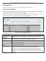
Port Settings..................................................................................................................................................................................................11
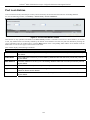
Port Description ............................................................................................................................................................................................12
Port Error Disabled .......................................................................................................................................................................................12
Static ARP Settings...................................................................................................................................................................... 13
User Accounts .............................................................................................................................................................................. 14
Admin and User Privileges ......................................................................................................................................................................14
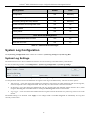
System Log Configuration ........................................................................................................................................................... 15
System Log Settings......................................................................................................................................................................................15
System Log Host...........................................................................................................................................................................................16
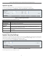
System Severity Settings.............................................................................................................................................................. 16
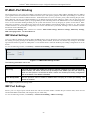
DHCP/BOOTP Relay................................................................................................................................................................... 17
DHCP/BOOTP Relay Global Settings ..........................................................................................................................................................17
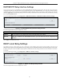
DHCP/BOOTP Relay Interface Settings.......................................................................................................................................................20
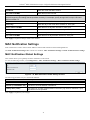
DHCP Local Relay Settings......................................................................................................................................................... 20
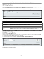
DHCP Auto Configuration Settings ............................................................................................................................................. 21
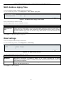
MAC Address Aging Time .......................................................................................................................................................... 22
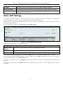
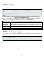
Web Settings ................................................................................................................................................................................ 22
iii
xStack® DGS-3200 Series Layer 2 Gigabit Ethernet Managed Switch
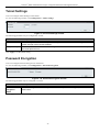
Telnet Settings.............................................................................................................................................................................. 23
Password Encryption.................................................................................................................................................................... 23
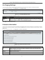
CLI Paging Settings ..................................................................................................................................................................... 24
Firmware Information .................................................................................................................................................................. 24
Power Saving Settings.................................................................................................................................................................. 25
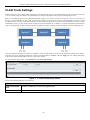
Dual Configuration Settings......................................................................................................................................................... 26
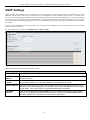
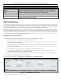
SMTP Settings ............................................................................................................................................................................. 27
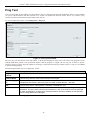
Ping Test ...................................................................................................................................................................................... 28
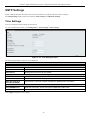
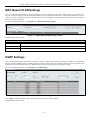
SNTP Settings .............................................................................................................................................................................. 29
Time Settings ................................................................................................................................................................................................29
TimeZone Settings ........................................................................................................................................................................................30
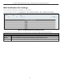
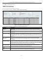
MAC Notification Settings .......................................................................................................................................................... 31
MAC Notification Global Settings................................................................................................................................................................31
MAC Notification Port Settings....................................................................................................................................................................32
SNMP Settings............................................................................................................................................................................. 33
SNMP Global State Settings .........................................................................................................................................................................34
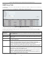
SNMP View Table........................................................................................................................................................................................34
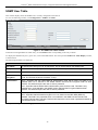
SNMP Group Table ......................................................................................................................................................................................35
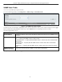
SNMP User Table .........................................................................................................................................................................................36
SNMP Community Table..............................................................................................................................................................................37
SNMP Host Table .........................................................................................................................................................................................38
SNMP v6Host Table .....................................................................................................................................................................................39
SNMP Engine ID ..........................................................................................................................................................................................40
SNMP Trap Configuration............................................................................................................................................................................40
RMON ..........................................................................................................................................................................................................40
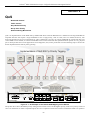
Single IP Management ................................................................................................................................................................. 41
Single IP Settings..........................................................................................................................................................................................43
Topology.......................................................................................................................................................................................................44
Firmware Upgrade ........................................................................................................................................................................................51
Configuration File Backup/Restore...............................................................................................................................................................51
Upload Log File ............................................................................................................................................................................................51
Layer 2 Features ............................................................................................................................................52
Jumbo Frame................................................................................................................................................................................ 52
Egress Filter Settings.................................................................................................................................................................... 53
802.1Q VLAN.............................................................................................................................................................................. 53
802.1v Protocol VLAN ................................................................................................................................................................ 62
802.1v Protocol Group Settings ....................................................................................................................................................................62
802.1v Protocol VLAN Settings ...................................................................................................................................................................62
MAC Based VLAN Settings ........................................................................................................................................................ 64
GVRP Settings ............................................................................................................................................................................. 64
PVID Auto Assign Settings ......................................................................................................................................................... 65
Trunking....................................................................................................................................................................................... 66
VLAN Trunk Settings .................................................................................................................................................................. 68
LACP Port Settings...................................................................................................................................................................... 69
iv
xStack® DGS-3200 Series Layer 2 Gigabit Ethernet Managed Switch
Traffic Segmentation.................................................................................................................................................................... 70
IGMP Snooping ........................................................................................................................................................................... 70
IGMP Snooping Settings ..............................................................................................................................................................................70
Data Driven Learning Settings......................................................................................................................................................................71
ISM VLAN Settings......................................................................................................................................................................................72
Restrictions and Provisos.........................................................................................................................................................................72
ISM Profile Settings......................................................................................................................................................................................73
IP Multicast Profile Settings .........................................................................................................................................................................73
Limited Multicast Address Range Settings ...................................................................................................................................................74
Max Multicast Group Settings ......................................................................................................................................................................75
MLD Snooping Settings............................................................................................................................................................... 75
Port Mirroring .............................................................................................................................................................................. 77
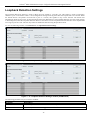
Loopback Detection Settings ....................................................................................................................................................... 78
Spanning Tree .............................................................................................................................................................................. 79
STP Bridge Global Settings ..........................................................................................................................................................................81
STP Port Settings ..........................................................................................................................................................................................82
MST Configuration Identification.................................................................................................................................................................84
STP Instance Settings....................................................................................................................................................................................85
MSTP Port Information ................................................................................................................................................................................86
Forwarding & Filtering ................................................................................................................................................................ 87
Unicast Forwarding.......................................................................................................................................................................................87
Multicast Forwarding....................................................................................................................................................................................87
Multicast Filtering Mode...............................................................................................................................................................................88
QoS ..................................................................................................................................................................89
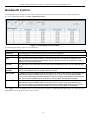
Bandwidth Control....................................................................................................................................................................... 91
Traffic Control ............................................................................................................................................................................. 92
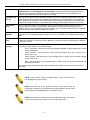
802.1p Default Priority................................................................................................................................................................. 94
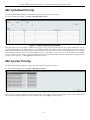
802.1p User Priority ..................................................................................................................................................................... 94
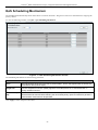
QoS Scheduling Mechanism ........................................................................................................................................................ 95
Security ...........................................................................................................................................................96
Safeguard Engine ......................................................................................................................................................................... 96
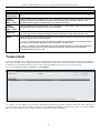
Trusted Host................................................................................................................................................................................. 98
IP-MAC-Port Binding.................................................................................................................................................................. 99
IMP Global Settings......................................................................................................................................................................................99
IMP Port Settings..........................................................................................................................................................................................99
IMP Entry Settings......................................................................................................................................................................................101
DHCP Snooping Entries .............................................................................................................................................................................101
MAC Block List..........................................................................................................................................................................................102
Port Security............................................................................................................................................................................... 103
Port Security Settings..................................................................................................................................................................................103
Port Lock Entries ........................................................................................................................................................................................104
DHCP Server Screening............................................................................................................................................................. 105
DHCP Screening Port Settings....................................................................................................................................................................105
DHCP Offer Filtering..................................................................................................................................................................................105
v
xStack® DGS-3200 Series Layer 2 Gigabit Ethernet Managed Switch
Guest VLAN .............................................................................................................................................................................. 107
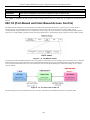
802.1X (Port-Based and Host-Based Access Control)............................................................................................................... 108
Authentication Server ............................................................................................................................................................................109
Authenticator .........................................................................................................................................................................................109
Client .....................................................................................................................................................................................................110
Authentication Process ..........................................................................................................................................................................110
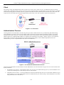
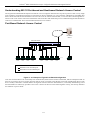
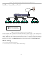
Understanding 802.1X Port-based and Host-based Network Access Control........................................................................................111
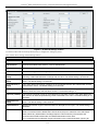
802.1X Settings...........................................................................................................................................................................................112
802.1X User ................................................................................................................................................................................................114
Initialize Port(s) ..........................................................................................................................................................................................115
Reauthenticate Port(s) .................................................................................................................................................................................116
Authentic RADIUS Server..........................................................................................................................................................................117
SSL Settings............................................................................................................................................................................... 118
SSH ............................................................................................................................................................................................ 120
SSH Configuration......................................................................................................................................................................................120
SSH Authmode and Algorithm Settings .....................................................................................................................................................121
SSH User Authentication Mode..................................................................................................................................................................123
Access Authentication Control................................................................................................................................................... 124
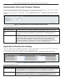
Authentication Policy and Parameter Settings ............................................................................................................................................125
Application Authentication Settings ...........................................................................................................................................................125
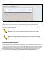
Authentication Server Group ......................................................................................................................................................................126
Authentication Server Host .........................................................................................................................................................................127
Login Method Lists.....................................................................................................................................................................................129
Enable Method Lists ...................................................................................................................................................................................130
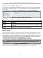
Configure Local Enable Password ..............................................................................................................................................................131
Enable Admin .............................................................................................................................................................................................131
MAC-based Access Control....................................................................................................................................................... 132
MAC-based Access Control Settings ..........................................................................................................................................................132
MAC-based Access Control Local Settings ................................................................................................................................................134
Web-based Access Control (WAC) ........................................................................................................................................... 134
WAC Global Settings..................................................................................................................................................................................136
WAC User Settings.....................................................................................................................................................................................137
WAC Port Settings......................................................................................................................................................................................138
JWAC......................................................................................................................................................................................... 139
JWAC Global Settings ................................................................................................................................................................................139
JWAC Port Settings ....................................................................................................................................................................................141
JWAC User Settings ...................................................................................................................................................................................142
JWAC Customize Page Language ..............................................................................................................................................................142
JWAC Customize Page...............................................................................................................................................................................143
Multiple Authentication ............................................................................................................................................................. 143
Authorization Network State Settings.........................................................................................................................................................146
Multiple Authentication Settings ................................................................................................................................................................146
Guest VLAN ...............................................................................................................................................................................................147
IGMP Access Control Settings (IGMP Authentication) ............................................................................................................ 148
ACL ...............................................................................................................................................................149
vi
xStack® DGS-3200 Series Layer 2 Gigabit Ethernet Managed Switch
Access Profile List ..................................................................................................................................................................... 149
CPU Access Profile List............................................................................................................................................................. 163
Time Range Settings .................................................................................................................................................................. 176
Monitoring ....................................................................................................................................................177
Device Environment................................................................................................................................................................... 177
Cable Diagnostic ........................................................................................................................................................................ 178
CPU Utilization.......................................................................................................................................................................... 178
Port Utilization........................................................................................................................................................................... 180
Packet Size ................................................................................................................................................................................. 181
Packets ....................................................................................................................................................................................... 183
Received (RX) ............................................................................................................................................................................................183
UMB_cast (RX) ..........................................................................................................................................................................................185
Transmitted (TX) ........................................................................................................................................................................................186
Errors.......................................................................................................................................................................................... 188
Received (RX) ............................................................................................................................................................................................188
Transmitted (TX) ........................................................................................................................................................................................190
Port Access Control.................................................................................................................................................................... 192
Authenticator State......................................................................................................................................................................................192
Authenticator Statistics ...............................................................................................................................................................................194
Authenticator Session Statistics ..................................................................................................................................................................196
Authenticator Diagnostics...........................................................................................................................................................................198
RADIUS Authentication .............................................................................................................................................................................200
RADIUS Account Client.............................................................................................................................................................................201
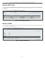
Browse ARP Table..................................................................................................................................................................... 203
Browse VLAN ........................................................................................................................................................................... 203
Browse Router Port .................................................................................................................................................................... 204
Browse MLD Router Port .......................................................................................................................................................... 204
Browse Session Table ................................................................................................................................................................ 205
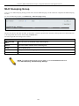
IGMP Snooping Group .............................................................................................................................................................. 205
MLD Snooping Group ............................................................................................................................................................... 206
WAC Authenticating State......................................................................................................................................................... 207
JWAC Host Table ...................................................................................................................................................................... 208
MAC Address Table .................................................................................................................................................................. 209
System Log ................................................................................................................................................................................ 210
MAC-based Access Control Authentication State ..................................................................................................................... 211
Save Services and Tools...............................................................................................................................212
Save Configuration ID 1 ............................................................................................................................................................ 212
Save Configuration ID 2 ............................................................................................................................................................ 213
Save Log .................................................................................................................................................................................... 213
Save All...................................................................................................................................................................................... 213
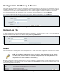
Configuration File Backup & Restore........................................................................................................................................ 214
Upload Log File ......................................................................................................................................................................... 214
Reset........................................................................................................................................................................................... 214
vii
xStack® DGS-3200 Series Layer 2 Gigabit Ethernet Managed Switch
Download Firmware................................................................................................................................................................... 215
Reboot System ........................................................................................................................................................................... 215
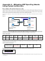
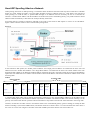
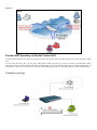
Appendix A – Mitigating ARP Spoofing Attacks Using Packet Content ACL ......................................216
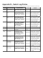
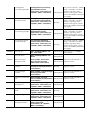
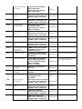
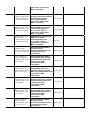
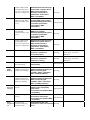
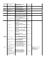
Appendix B – Switch Log Entries...............................................................................................................223
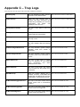
Appendix C – Trap Logs .............................................................................................................................234
Appendix D – Password Recovery Procedure...........................................................................................237
Appendix E – Glossary ................................................................................................................................238
Warranty & Support....................................................................................................................................240
viii
xStack® DGS-3200 Series Layer 2 Gigabit Ethernet Managed Switch
Intended Readers
The DGS-3200 Series Manual contains information for setup and management of the Switch. This manual is intended for
network managers familiar with network management concepts and terminology.
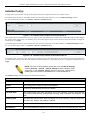
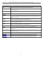
Typographical Conventions
Convention
Description
[]
In a command line, square brackets indicate an optional entry. For example: [copy
filename] means that optionally you can type copy followed by the name of the file. Do
not type the brackets.
Bold font
Indicates a button, a toolbar icon, menu, or menu item. For example: Open the File
menu and choose Cancel. Used for emphasis. May also indicate system messages or
prompts appearing on screen. For example: You have mail. Bold font is also used to
represent filenames, program names and commands. For example: use the copy
command.
Boldface
Font
Typewriter
Indicates commands and responses to prompts that must be typed exactly as printed in
the manual.
Initial capital letter
Indicates a window name. Names of keys on the keyboard have initial capitals. For
example: Click Enter.
Italics
Indicates a window name or a field. Also can indicate a variables or parameter that is
replaced with an appropriate word or string. For example: type filename means that the
actual filename should be typed instead of the word shown in italic.
Menu Name > Menu
Option
Menu Name > Menu Option Indicates the menu structure. Device > Port > Port
Properties means the Port Properties menu option under the Port menu option that is
located under the Device menu.
ix
xStack® DGS-3200 Series Layer 2 Gigabit Ethernet Managed Switch
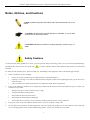
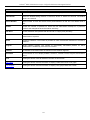
Notes, Notices, and Cautions
A NOTE indicates important information that helps make better use of the
device.
A NOTICE indicates either potential damage to hardware or loss of data
and tells how to avoid the problem.
A CAUTION indicates a potential for property damage, personal injury, or
death.
Safety Cautions
Use the following safety guidelines to ensure your own personal safety and to help protect your system from potential damage.
Throughout this safety section, the caution icon (
followed.
) is used to indicate cautions and precautions that need to be reviewed and
To reduce the risk of bodily injury, electrical shock, fire, and damage to the equipment, observe the following precautions.
•
•
Observe and follow service markings.
•
Do not service any product except as explained in the system documentation.
•
Opening or removing covers that are marked with the triangular symbol with a lightning bolt may expose the user to
electrical shock.
•
Only a trained service technician should service components inside these compartments.
If any of the following conditions occur, unplug the product from the electrical outlet and replace the part or contact your
trained service provider:
•
Damage to the power cable, extension cable, or plug.
•
An object has fallen into the product.
•
The product has been exposed to water.
•
The product has been dropped or damaged.
•
The product does not operate correctly when the operating instructions are correctly followed.
•
Keep your system away from radiators and heat sources. Also, do not block cooling vents.
•
Do not spill food or liquids on system components, and never operate the product in a wet environment. If the system gets
wet, see the appropriate section in the troubleshooting guide or contact your trained service provider.
x
xStack® DGS-3200 Series Layer 2 Gigabit Ethernet Managed Switch
•
Do not push any objects into the openings of the system. Doing so can cause fire or electric shock by shorting out interior
components.
•
Use the product only with approved equipment.
•
Allow the product to cool before removing covers or touching internal components.
•
Operate the product only from the type of external power source indicated on the electrical ratings label. If unsure of the type
of power source required, consult your service provider or local power company.
•
To help avoid damaging the system, be sure the voltage selection switch (if provided) on the power supply is set to match the
power available at the Switch’s location:
•
115 volts (V)/60 hertz (Hz) in most of North and South America and some Far Eastern countries such as South Korea
and Taiwan
•
100 V/50 Hz in eastern Japan and 100 V/60 Hz in western Japan
•
230 V/50 Hz in most of Europe, the Middle East, and the Far East
•
Also, be sure that attached devices are electrically rated to operate with the power available in your location.
•
Use only approved power cable(s). If you have not been provided with a power cable for your system or for any ACpowered option intended for your system, purchase a power cable that is approved for use in your country. The power cable
must be rated for the product and for the voltage and current marked on the product's electrical ratings label. The voltage and
current rating of the cable should be greater than the ratings marked on the product.
•
To help prevent electric shock, plug the system and peripheral power cables into properly grounded electrical outlets. These
cables are equipped with three-prong plugs to help ensure proper grounding. Do not use adapter plugs or remove the
grounding prong from a cable. If using an extension cable is necessary, use a 3-wire cable with properly grounded plugs.
•
Observe extension cable and power strip ratings. Make sure that the total ampere rating of all products plugged into the
extension cable or power strip does not exceed 80 percent of the ampere ratings limit for the extension cable or power strip.
•
To help protect the system from sudden, transient increases and decreases in electrical power, use a surge suppressor, line
conditioner, or uninterruptible power supply (UPS).
•
Position system cables and power cables carefully; route cables so that they cannot be stepped on or tripped over. Be sure
that nothing rests on any cables.
•
Do not modify power cables or plugs. Consult a licensed electrician or your power company for site modifications. Always
follow your local/national wiring rules.
•
When connecting or disconnecting power to hot-pluggable power supplies, if offered with your system, observe the
following guidelines:
•
•
Install the power supply before connecting the power cable to the power supply.
•
Unplug the power cable before removing the power supply.
•
If the system has multiple sources of power, disconnect power from the system by unplugging all power cables from
the power supplies.
Move products with care; ensure that all casters and/or stabilizers are firmly connected to the system. Avoid sudden stops
and uneven surfaces.
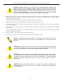
General Precautions for Rack-Mountable Products
Observe the following precautions for rack stability and safety. Also, refer to the rack installation documentation accompanying
the system and the rack for specific caution statements and procedures.
•
Systems are considered to be components in a rack. Thus, "component" refers to any system as well as to various peripherals
or supporting hardware.
xi
xStack® DGS-3200 Series Layer 2 Gigabit Ethernet Managed Switch
CAUTION: Installing systems in a rack without the front and side stabilizers installed could
cause the rack to tip over, potentially resulting in bodily injury under certain circumstances.
Therefore, always install the stabilizers before installing components in the rack. After
installing system/components in a rack, never pull more than one component out of the
rack on its slide assemblies at one time. The weight of more than one extended
component could cause the rack to tip over and may result in serious injury.
•
Before working on the rack, make sure that the stabilizers are secured to the rack, extended to the floor, and that the full
weight of the rack rests on the floor. Install front and side stabilizers on a single rack or front stabilizers for joined multiple
racks before working on the rack.
•
Always load the rack from the bottom up, and load the heaviest item in the rack first.
•
Make sure that the rack is level and stable before extending a component from the rack.
•
Use caution when pressing the component rail release latches and sliding a component into or out of a rack; the slide rails
can pinch your fingers.
•
After a component is inserted into the rack, carefully extend the rail into a locking position, and then slide the component
into the rack.
•
Do not overload the AC supply branch circuit that provides power to the rack. The total rack load should not exceed 80
percent of the branch circuit rating.
•
Ensure that proper airflow is provided to components in the rack.
•
Do not step on or stand on any component when servicing other components in a rack.
NOTE: A qualified electrician must perform all connections to DC power and to safety
grounds. All electrical wiring must comply with applicable local or national codes and
practices.
CAUTION: Never defeat the ground conductor or operate the equipment in the absence
of a suitably installed ground conductor. Contact the appropriate electrical inspection
authority or an electrician if uncertain that suitable grounding is available.
CAUTION: The system chassis must be positively grounded to the rack cabinet frame.
Do not attempt to connect power to the system until grounding cables are connected.
Completed power and safety ground wiring must be inspected by a qualified electrical
inspector. An energy hazard will exist if the safety ground cable is omitted or
disconnected.
CAUTION: When mounting the Switch on a cement wall, a proper concrete sleeve
anchor should be used, such as the one that is included in the optional D-Link Wall Mount
kit (DRE-KIT018).
xii
xStack® DGS-3200 Series Layer 2 Gigabit Ethernet Managed Switch
Lithium Battery Precaution
CAUTION: Incorrectly replacing the lithium battery of the Switch may cause the battery to
explode. Replace this battery only with the same or equivalent type recommended by the
manufacturer. Discard used batteries according to the manufacturer’s instructions.
Protecting Against Electrostatic Discharge
Static electricity can harm delicate components inside the system. To prevent static damage, discharge static electricity from your
body before touching any of the electronic components, such as the microprocessor. This can be done by periodically touching an
unpainted metal surface on the chassis.
The following steps can also be taken prevent damage from electrostatic discharge (ESD):
1.
When unpacking a static-sensitive component from its shipping carton, do not remove the component from the antistatic
packing material until ready to install the component in the system. Just before unwrapping the antistatic packaging, be
sure to discharge static electricity from your body.
2.
When transporting a sensitive component, first place it in an antistatic container or packaging.
3.
Handle all sensitive components in a static-safe area. If possible, use antistatic floor pads, workbench pads and an
antistatic grounding strap.
xiii
xStack® DGS-3200 Series Layer 2 Gigabit Ethernet Managed Switch
Section 1
Web-based Switch Configuration
Introduction
Logging onto the Web Manager
Web-Based User Interface
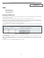
Introduction
All software functions of the Switch can be managed, configured, and monitored via the embedded web-based (HTML) interface.
Manage the Switch from remote stations anywhere on the network through a standard browser, such as Internet Explorer 5.5 or
later, Netscape 8.0 or later, or Firefox 2.0 or later. The browser acts as a universal access tool and can communicate directly with
the Switch using the HTTP protocol.
The Web-based management module and the Console program (and Telnet) are different ways to access the same internal
switching software and configure it. Thus, all settings encountered in web-based management are the same as those found in the
console program.
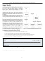
Logging onto the Web Manager
To begin managing the Switch, simply run the browser installed on your computer and point it to the IP address you have defined
for the device. The URL in the address bar should read something like: http://123.123.123.123, where the numbers 123 represent
the IP address of the Switch.
NOTE: The factory default IP address is 10.90.90.90.
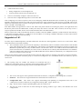
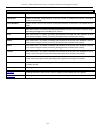
This opens the management module's user authentication window, as seen below.
Figure 1- 1. Enter Network Password window
Enter “admin” in both the User Name field and the Password field and click OK. This will open the Web-based user interface.
The Switch management features available in the web-based manager are explained below.
1
xStack® DGS-3200 Series Layer 2 Gigabit Ethernet Managed Switch
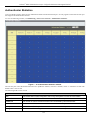
Web-based User Interface
The user interface provides access to various Switch configuration and management windows, allows the user to view
performance statistics, and permits graphical monitoring of the system status.
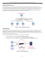
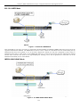
Areas of the User Interface
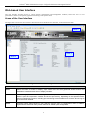
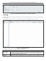
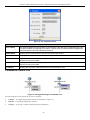
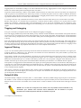
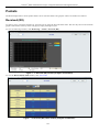
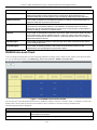
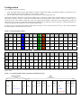
The figure below shows the user interface. Three distinct areas divide the user interface, as described in the table.
Area 2
Area 3
Area 1
Figure 1- 2. Main Web-Manager window
Area
Function
Area 1
Select the folder or window to display. Open folders and click the hyperlinked window buttons and
subfolders contained within them to display windows.
Area 2
Presents a graphical near real-time image of the front panel of the Switch. This area displays the
Switch's ports and expansion modules and shows port activity, depending on the specified mode.
Some management functions, including port monitoring are accessible here. Click the D-Link logo to
go to the D-Link website.
Area 3
Presents Switch status based on user selection and the entry of configuration data. In addition,
hyperlinks are offered for many Switch features to enable quick configuration.
2
xStack® DGS-3200 Series Layer 2 Gigabit Ethernet Managed Switch
Web Pages
When connecting to the management mode of the Switch with a web browser, a login screen is displayed. Enter a user name and
password to access the Switch's management mode.
Below is a list of the folders and windows available in the web interface:
Configuration – Contains the following main folders, windows, and related windows: System Information, Serial Port Settings,
IP Address, IPv6 Interface Settings, IPv6 Route Table, IPv6 Neighbor Settings, Port Configuration, Port Settings, Port Description,
Port Error Disabled, Static ARP Settings, User Accounts, System Log Configuration, System Log Settings, System Log Host,
System Severity Settings, DHCP/BOOTP Relay, DHCP/BOOTP Relay Global Settings, DHCP/BOOTP Relay Interface Settings,
DHCP Local Relay Settings, DHCP Auto Configuration Settings, MAC Address Aging Time, Web Settings, Telnet Settings,
Password Encryption, CLIpaging Settings, Firmware Information, Power Saving Settings, Dual Configuration Settings, SMTP
Settings, Ping Test, SNTP Settings, Time Settings, TimeZone Settings, MAC Notification Settings, MAC Notification Global
Settings, MAC Notification Port Settings, SNMP Settings, SNMP Global Settings, SNMP View Table, SNMP Group Table,
SNMP User Table, SNMP Community Table, SNMP Host Table, SNMP v6Host Table, SNMP Engine ID, SNMP Trap
Configuration, RMON, Single IP Management, Single IP Settings, Topology, Firmware Upgrade, Configuration File
Backup/Restore, and Upload Log File.
L2 Features – Contains the following main folders, windows, and related windows: Jumbo Frame, Egress Filter Settings, 802.1Q
VLAN, 802.1Q Protocol VLAN, Protocol VLAN Group Settings, Protocol VLAN Port Settings, MAC Based VLAN Settings,
GVRP Settings, PVID Auto Assign Settings, Trunking, LACP Port Settings, Traffic Segmentation, IGMP Snooping, IGMP
Snooping Settings, Data Driven Learning Settings, ISM VLAN Settings, IP Multicast Profile Settings, Limited Multicast Address
Range Settings, Max Multicast Group Settings, MLD Snooping Settings, Port Mirroring, Loopback Detection Settings, Spanning
Tree, STP Bridge Global Settings, STP Port Settings, MST Configuration Identification, STP Instance Settings, MSTP Port
Information, Forwarding & Filtering, Unicast Forwarding, Multicast Forwarding, and Multicast Filtering Mode.
QoS – Contains the following main folders, windows, and related windows: Bandwidth Control, Traffic Control, 802.1p Default
Priority, 802.1p User Priority, and QoS Scheduling Mechanism.
Security – Contains the following main folders, windows, and related windows: Safeguard Engine, Trusted Host, IP-MAC-Port
Binding, IMP Global Settings, IMP Port Settings, IMP Entry Settings, DHCP Snooping Entries, MAC Block List, Port Security,
Port Security Settings, Port Lock Entries, DHCP Server Screening, DHCP Screening Port Settings, DHCP Offer Filtering, Guest
VLAN, 802.1X, 802.1X Settings, 802.1X User, Initialize Port(s), Reauthenticate Port(s), Authentic RADIUS Server, SSL Settings,
SSH, SSH Configuration, SSH Authmode and Algorithm Settings, SSH User Authentication Mode, Access Authentication
Control, Authentication Policy and Parameter Settings, Application Authentication Settings, Authentication Server Group,
Authentication Server Host, Login Method Lists, Enable Method Lists, Configure Local Enable Password, Enable Admin, MAC
Based Access Control, MAC Based Access Control Global Settings, MAC-based Access Control Local Settings, Web
Authentication, Web Global Settings, Web User Settings, Web Port Settings, JWAC, JWAC Global Settings, JWAC Port Settings,
JWAC User Settings, JWAC Customize Page Language, JWAC Customize Page, Multiple Authentication, Authorization
Network State Settings, Multiple Authentication Settings, Guest VLAN, and IGMP Access Control Settings.
ACL – Contains the following main folders, windows, and related windows: Access Profile List, CPU Access Profile List, and
Time Range Settings.
Monitoring – Contains the following main folders, windows, and related windows: Device Environment, Cable Diagnostic, CPU
Utilization, Port Utilization, Packet Size, Packets, Received (RX), UMB_cast (RX), Transmitted (TX), Errors, Received (RX),
Transmitted (TX), Port Access Control, RADIUS Authentication, RADIUS Account Client, Authenticator State, Authenticator
Statistics, Authenticator Session Statistics, Authenticator Diagnostics, Browse ARP Table, Browse VLAN, Browse Router Port,
Browse MLD Router Port, Browse Session Table, IGMP Snooping Group, MLD Snooping Group, WAC Authenticating State,
JWAC Host Table, MAC Address Table, System Log, and MAC-based Access Control Authentication State.
Save – Contains links for Save Configuration ID 1, Save Configuration ID 2, Save Log, and Save All.
Tools – Contains the following windows: Configuration File Backup & Restore, Upload Log File, Reset, Download Firmware,
and Reboot System.
NOTE: Be sure to configure the user name and password in the User
Accounts window before connecting the Switch to the greater network.
3
xStack® DGS-3200 Series Layer 2 Gigabit Ethernet Managed Switch
Section 2
Configuration
Device Information
System Information
Serial Port Settings
IP Address
IPv6 Interface Settings
IPv6 Route Table
IPv6 Neighbor Settings
Port Configuration
Static ARP Settings
User Accounts
System Log Configuration
System Severity Settings
DHCP/BOOTP Relay
DHCP Local Relay Settings
DHCP Auto Configuration Settings
MAC Address Aging Time
Web Settings
Telnet Settings
Password Encryption
CLI Paging Settings
Firmware Information
Power Saving Settings
Dual Configuration Settings
SMTP Settings
Ping Test
SNTP Settings
MAC Notification Settings
SNMP Settings
Single IP Management
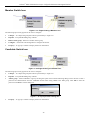
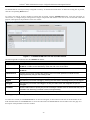
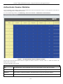
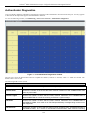
Device Information
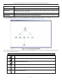
This window contains the main settings for all major functions for the Switch. It appears automatically when you log on to the
Switch. To return to the Device Information window after viewing other windows, click the DGS-3200-10/DGS-3200-16 folder.
The Device Information window shows the Switch’s MAC Address (assigned by the factory and unchangeable), the Boot PROM
Version, Firmware Version, Hardware Version, and many other important types of information. This is helpful to keep track of
PROM and firmware updates and to obtain the Switch’s MAC address for entry into another network device’s address table, if
necessary. In addition, this window displays the status of functions on the Switch to quickly assess their current global status.
Many functions are hyper-linked for easy access to enable quick configuration from this window.
4
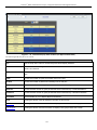
xStack® DGS-3200 Series Layer 2 Gigabit Ethernet Managed Switch
Figure 2- 1. Device Information window
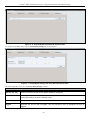
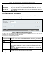
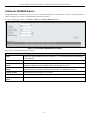
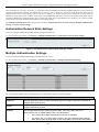
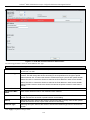
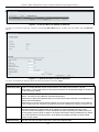
System Information
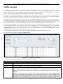
The user can enter a System Name, System Location, and System Contact to aid in defining the Switch.
To view the following window, click Configuration > System Information:
Figure 2- 2. System Information window
The fields that can be configured are described below:
Parameter
Description
System Name
Enter a system name for the Switch, if so desired. This name will identify it in the Switch
network.
System Location
Enter the location of the Switch, if so desired.
System Contact
Enter a contact name for the Switch, if so desired.
Click Apply to implement changes made.
5
xStack® DGS-3200 Series Layer 2 Gigabit Ethernet Managed Switch
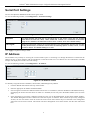
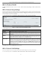
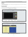
Serial Port Settings
The user can adjust the Baud Rate and the Auto Logout values.
To view the following window, click Configuration > Serial Port Settings:
Figure 2- 3. Serial Port Settings window
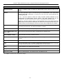
Baud Rate
This field specifies the baud rate for the serial port on the Switch. There are four possible
baud rates to choose from, 9600, 19200, 38400 and 115200. For a connection to the Switch
using the CLI interface, the baud rate must be set to 115200, which is the default setting.
Auto Logout
Select the logout time used for the console interface. This automatically logs the user out after
an idle period of time, as defined. Choose from the following options: 2 mins, 5 mins, 10 mins,
15 mins or Never. The default setting is 10 mins.
Click Apply to implement changes made.
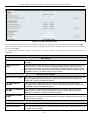
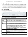
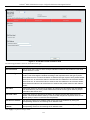
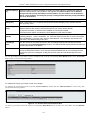
IP Address
The IP address may initially be set using the console interface prior to connecting to it through the Ethernet. If the Switch IP
address has not yet been changed, read the introduction of the DGS-3200 Series CLI Manual for more information. TheWeb
manager will display the Switch’s current IP settings.
To view the following window, click Configuration > IP Address:
Figure 2- 4. IP Address window
To manually assign the Switch’s IP address, subnet mask, and default gateway address:
1.
Click the Manual radio button at the top of the window.
2.
Enter the appropriate IP Address and Subnet Mask.
3.
If accessing the Switch from a different subnet from the one it is installed on, enter the IP address of the default Gateway.
If managing the Switch from the subnet on which it is installed, the user may leave the default address (0.0.0.0) in this
field.
4.
If the Switch has no previously configured VLANs, the user can use the Management VLAN Name entitled “default”.
This default Management VLAN contains all of the Switch ports as members. If the Switch has previously configured
VLANs, the user will need to enter the VLAN ID of the VLAN that contains the port connected to the management
station that will access the Switch. The Switch will allow management access from stations with the same VID listed
here.
6
xStack® DGS-3200 Series Layer 2 Gigabit Ethernet Managed Switch
NOTE: The Switch’s factory default IP address is 10.90.90.90 with a
subnet mask of 255.0.0.0 and a default gateway of 0.0.0.0.
To use the DHCP or BOOTP protocols to assign the Switch an IP address, subnet mask, and default gateway address:
Use the radio button at the top of the window to choose either DHCP or BOOTP. This selects the method the Switch assigns an IP
address on the next reboot.
The following parameters may be configured or viewed:
Parameter
Description
Manual
Allows the entry of an IP address, subnet mask, and a default gateway for the Switch. These fields
should be of the form xxx.xxx.xxx.xxx, where each xxx is a number (represented in decimal form)
between 0 and 255. This address should be a unique address on the network assigned for use by
the network administrator.
DHCP
The Switch will send out a DHCP broadcast request when it is powered up. The DHCP protocol
allows IP addresses, network masks, and default gateways to be assigned by a DHCP server. If
this option is set, the Switch will first look for a DHCP server to provide it with this information
before using the default or previously entered settings.
BOOTP
The Switch will send out a BOOTP broadcast request when it is powered up. The BOOTP protocol
allows IP addresses, network masks, and default gateways to be assigned by a central BOOTP
server. If this option is set, the Switch will first look for a BOOTP server to provide it with this
information before using the default or previously entered settings.
Subnet Mask
A Bitmask that determines the extent of the subnet that the Switch is on. Should be of the form
xxx.xxx.xxx.xxx, where each xxx is a number (represented in decimal) between 0 and 255. The
value should be 255.0.0.0 for a Class A network, 255.255.0.0 for a Class B network, and
255.255.255.0 for a Class C network, but custom subnet masks are allowed.
Gateway
IP address that determines where packets with a destination address outside the current subnet
should be sent. This is usually the address of a router or a host acting as an IP gateway. If your
network is not part of an intranet, or you do not want the Switch to be accessible outside your local
network, you can leave this field unchanged.
Management
VLAN Name
This allows the entry of a VLAN name from which a management station will be allowed to manage
the Switch using TCP/IP (in-band via Web manager or Telnet). Management stations that are on
VLANs other than the one entered here will not be able to manage the Switch in-band unless their
IP addresses are entered in the Trusted Host window (Security > Trusted Host). If VLANs have
not yet been configured for the Switch, the default VLAN contains all of the Switch’s ports. There
are no entries in the Trusted Host table, by default, so any management station that can connect to
the Switch can access the Switch until a management VLAN is specified or Management Station IP
addresses are assigned.
Click Apply to implement changes made.
7
xStack® DGS-3200 Series Layer 2 Gigabit Ethernet Managed Switch
Setting the Switch’s IP Address using the Console Interface
Each Switch must be assigned its own IP Address, which is used for communication with an SNMP network manager or other
TCP/IP application (for example BOOTP, TFTP). The Switch’s default IP address is 10.90.90.90. The default Switch IP address
can be changed to meet the specification of your networking address scheme.
The IP address for the Switch must be set before the Web-based manager can manage the switch. The Switch IP address can be
automatically set using BOOTP or DHCP protocols, in which case the actual address assigned to the Switch must be known. The
IP address may be set using the Command Line Interface (CLI) over the console serial port as follows:
•
Starting at the command line prompt, enter the commands config ipif System ipaddress xxx.xxx.xxx.xxx/
yyy.yyy.yyy.yyy. Where the x’s represent the IP address to be assigned to the IP interface named System and the y’s
represent the corresponding subnet mask.
•
Alternatively, the user can enter config ipif System ipaddress xxx.xxx.xxx.xxx/z. Where the x’s represent the IP
address to be assigned to the IP interface named System and the z represents the corresponding number of subnets in
CIDR notation.
The IP interface named System on the Switch can be assigned an IP address and subnet mask, which can then be used to connect a
management station to the Switch’s Telnet or Web-based management agent.
Successful entry of the command will produce a “Success” message, indicating that the command execution was correctly. The
user may now utilize this address to configure or manage the Switch through Telnet, the Command Line Interface (CLI) or the
Web-based management (GUI).
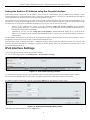
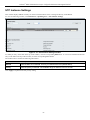
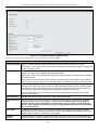
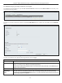
IPv6 Interface Settings
Users can display the Switch’s current IPv6 interface settings.
To view the following window, click Configuration > IPv6 Interfaces Settings:
Figure 2- 5. IPv6 Interface Settings window
To configure IPv6 interface settings, enter an Interface Name, a VLAN Name, and make sure the Interface Admin. State is
Enabled. Click the Create button. The new entry will appear in the Interface Table at the bottom of the window.
To modify an Interface Table entry, click the corresponding Edit button. The following window opens:
Figure 2- 6. IPv6 Interface Settings (Edit) window
After making the desired changes, click the Apply button.
8
xStack® DGS-3200 Series Layer 2 Gigabit Ethernet Managed Switch
The following parameters may be configured or viewed:
Parameter
Description
Interface Name
The name of the IPv6 interface being modified.
VLAN Name
Enter the VLAN name of the IPv6 interface.
IPv6 Address
Enter the IPv6 address of the interface to be modified.
Admin. State
Toggle the state between Enabled and Disabled.
NS Retransmit
Time (04294967295)
Enter a value between 0 and 4294967295. This is the neighbor solicitation’s retransmit timer in
milliseconds. The default is zero.
Automatic Link
Local Address
Toggle between Enabled and Disabled. Enabling this is helpful when no external source of network
addressing information is available.
Default
Gateway
Enter the IPv6 address of the default gateway.
Active
This read-only field indicates the status of this entry.
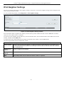
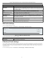
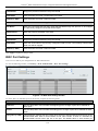
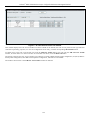
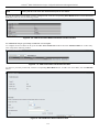
IPv6 Route Table
The user can configure the Switch’s IPv6 Route Table.
To view the following window, click Configuration > IPv6 Route Table:
Figure 2- 7. IPv6 Route Table window
Enter an IPv6 address in the Gateway field and click the Create button.
9
xStack® DGS-3200 Series Layer 2 Gigabit Ethernet Managed Switch
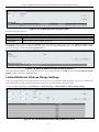
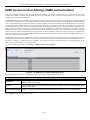
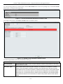
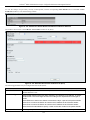
IPv6 Neighbor Settings
The user can configure the Switch’s IPv6 neighbor settings. The Switch’s current IPv6 neighbor settings will be displayed in the
table at the bottom of this window.
To view the following window, click Configuration > IPv6 Neighbor Settings:
Figure 2- 8. IPv6 Neighbor Settings window
Enter the Interface Name, Neighbor IPv6 Address, and the Link Layer MAC Address and then click the Add button. The State
can be set to All, Address, Static, or Dynamic.
To look for an IPv6 Neighbor Settings table entry, enter the Interface Name, select the desired State in the middle section of this
window, and then click the Find button.
To delete all the entries being displayed on the table at the bottom of this window, click the Clear button.
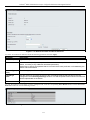
The following parameters may be configured or viewed:
Parameter
Description
Interface Name
Enter the name of the IPv6 neighbor. To search for all the current interfaces on the Switch, go to
the second Interface Name field in the middle part of the window, tick the All check box, and then
click the Find button.
Neighbor IPv6
Address
Enter the neighbor IPv6 address.
Link Layer MAC
Address
Enter the link layer MAC address.
State
Use the drop-down menu to select All, Address, Static, or Dynamic.
10
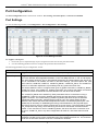
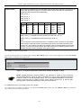
xStack® DGS-3200 Series Layer 2 Gigabit Ethernet Managed Switch
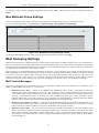
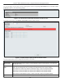
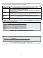
Port Configuration
The Port Configuration folder contains three windows: Port Settings, Port Description, and Port Error Disabled.
Port Settings
To view the following window, click Configuration > Port Configuration > Port Settings:
Figure 2- 9. Port Settings window
To configure switch ports:
1.
Choose the port or sequential range of ports using the From Port and To Port pull-down menus.
2.
Use the remaining pull-down menus to configure the parameters described below:
The following parameters may be configured or viewed:
Parameter
Description
State
Toggle the State field to either enable or disable a given port or group of ports.
Speed/Duplex
Toggle the Speed/Duplex field to either select the speed and duplex/half-duplex state of the
port. Auto denotes auto-negotiation between 10 and 100 Mbps devices, in full- or half-duplex.
The Auto setting allows the port to automatically determine the fastest settings the device the
port is connected to can handle, and then to use those settings. The other options are 10M
Half, 10M Full, 100M Half, 100M Full, 1000M Full_Master, 1000M Full_Slave, and 1000M Full.
There is no automatic adjustment of port settings with any option other than Auto.
The Switch allows the user to configure three types of gigabit connections; 1000M Full_Master,
1000M Full_Slave, and 1000M Full. Gigabit connections only support full duplex connections
and take on certain characteristics that are different from the other choices listed.
The 1000M Full_Master and 1000M Full_Slave parameters refer to connections running a
1000BASE-T cable for connection between the Switch port and other device capable of a
gigabit connection. The master setting (1000M Full_Master) will allow the port to advertise
capabilities related to duplex, speed and physical layer type. The master setting will also
determine the master and slave relationship between the two connected physical layers. This
relationship is necessary for establishing the timing control between the two physical layers.
The timing control is set on a master physical layer by a local source. The slave setting (1000M
Full_Slave) uses loop timing, where the timing comes from a data stream received from the
master. If one connection is set for 1000M Full_Master, the other side of the connection must
be set for 1000M Full_Slave. Any other configuration will result in a link down status for both
ports.
Flow Control
Displays the flow control scheme used for the various port configurations. Ports configured for
full-duplex use 802.3x flow control, half-duplex ports use backpressure flow conٛ onfi, and Auto
ports use an automatic selection of the two. The default is Disabled.
11
xStack® DGS-3200 Series Layer 2 Gigabit Ethernet Managed Switch
Address
Learning
Enable or disable MAC address learning for the selected ports. When Enabled, destination and
source MAC addresses are automatically listed in the forwarding table. When address learning
is Disabled, MAC addresses must be manually entered into the forwarding table. This is
sometimes done for reasons of security or efficiency. See the section on Forwarding/Filtering
for information on entering MAC addresses into the forwarding table. The default setting is
Enabled.
Medium Type
If configuring the Combo ports, this defines the type of transport medium to be used, whether
Copper or Fiber.
Click Apply to implement the new settings on the Switch.
Port Description
The Switch supports a port description feature where the user may name various ports.
To view the following window, click Configuration > Port Configuration > Port Description:
Figure 2- 10. Port Description window
Use the From Port and To Port pull-down menu to choose a port or range of ports to describe. Users may then enter a description
for the chosen port(s). If configuring the Combo ports, the Medium Type defines the type of transport medium to be used, whether
Copper or Fiber
Click Apply to set the descriptions in the Port Description window.
Port Error Disabled
The following window will display the information about ports that have had their connection status disabled, for reasons such as
storm control or link down status.
To view the following window, click Configuration > Port Configuration > Port Error Disabled:
Figure 2- 11. Port Error Disabled window
The following parameters are displayed:
Parameter
Description
Port
Displays the port that has been error disabled.
12
xStack® DGS-3200 Series Layer 2 Gigabit Ethernet Managed Switch
Port State
Describes the current running state of the port, whether enabled or disabled.
Connection Status
This field will read the uplink status of the individual ports, whether enabled or disabled.
Reason
Describes the reason why the port has been error-disabled, such as it has become a
shutdown port for storm control.
Static ARP Settings
The Address Resolution Protocol is a TCP/IP protocol that converts IP addresses into physical addresses. This table allows
network managers to view, define, modify, and delete ARP information for specific devices.
Static entries can be defined in the ARP table. When static entries are defined, a permanent entry is entered and is used to translate
IP addresses to MAC addresses.
To view the following window, click Configuration > Static ARP Settings:
Figure 2- 12. Static ARP Settings window
The following parameters may be configured or viewed:
Parameter
Description
ARP Aging Time
(0-65535)
The ARP entry age-out time, in seconds. The default is 20 minutes.
IP Address
The IP address of the ARP entry.
MAC Address
The MAC address of the ARP entry.
After entering a global ARP Aging Time in seconds, click Apply to allow it to take effect. The default value is 20 seconds.
After entering the IP Address and MAC Address of the Static ARP entry, click Apply to implement the new entry. To completely
clear the static ARP entries, click the Delete All button.
To modify a static ARP entry, click the Edit button located on the right side of the entry in the ARP table at the bottom of the
window.
To delete a static ARP entry, click the Delete button located on the right side of the entry in the static ARP table at the bottom of
the window.
13
xStack® DGS-3200 Series Layer 2 Gigabit Ethernet Managed Switch
User Accounts
The Switch allows the control of user privileges.
To view the following window, click Configuration > User Accounts:
Figure 2- 13. User Accounts window
To add a new user, type in a User Name and New Password and retype the same password in the Confirm New Password field.
Choose the level of privilege (Admin or User) from the Access Right drop-down menu.
Figure 2- 14. User Accounts window (modify)
Modify or delete an existing user account in the table at the bottom of the window. To delete the user account, click the Delete
button. To change the password, click the Edit button next to the entry in the table at the bottom of the window. Enter an Old
Password, New Password, and retype the new password in the Confirm Password field offered, use the drop-down menu to select
the type of encryption desired (Plain Text or Sha 1), and then click Apply. The level of privilege (Admin or User) can be viewed
in the Access Right column in the table at the bottom of the window.
NOTICE: In case of lost passwords or password corruption, please refer to the
Appendix D, “Password Recovery Procedure,” which will guide you through the
steps necessary to resolve this issue.
Admin and User Privileges
There are two levels of user privileges, Admin and User. Some menu selections available to users with Admin privileges may not
be available to those with User privileges.
The following table summarizes the Admin and User privileges:
14
xStack® DGS-3200 Series Layer 2 Gigabit Ethernet Managed Switch
Management
Admin
User
Configuration
Yes
Read-only
Network Monitoring
Yes
Read-only
Community Strings and Trap Stations
Yes
Read-only
Update Firmware and Configuration Files
Yes
No
System Utilities
Yes
No
Factory Reset
Yes
No
User Account Management
Add/Update/Delete User Accounts
Yes
No
View User Accounts
Yes
No
Table 2- 1. Admin and User Privileges
System Log Configuration
The System Log Configuration folder contains two windows: System Log Settings and System Log Host.
System Log Settings
The Switch allow users to choose a method for which to save the switch log to the flash memory of the Switch.
To view the following window, click Configuration > System Log Configuration > System Log Settings:
Figure 2- 15. System Log Settings window
Use the pull-down menu to choose the method for saving the switch log to the flash memory. The user has three options:
•
Time Interval – Users who choose this method can configure a time interval by which the Switch will save the log files,
in the box adjacent to this configuration field. The user may set a time between 1 and 65535 minutes.
•
On Demand – Users who choose this method will only save log files when they manually tell the Switch to do so, either
using the Save Log link in the Save folder or clicking the Save Log Now button on this window.
•
Log Trigger – Users who choose this method will have log files saved to the Switch every time a log event occurs on the
Switch.
The default setting is On Demand. Click Apply to save changes made. Click Save Log Now to immediately save log files
currently on the switch.
15
xStack® DGS-3200 Series Layer 2 Gigabit Ethernet Managed Switch
System Log Host
The Switch can send Syslog messages to up to four designated servers using the System Log Server.
To view the following window, click Configuration > System Log Configuration > System Log Host:
Figure 2- 16. System Log Host window
The following parameters may be configured or viewed:
Parameter
Description
Host ID
Syslog server settings index (1 to 4).
Host IP Address
The Ipv4 address of the Syslog server.
UDP Port (514 or
6000-65535)
Type the UDP port number used for sending Syslog messages. The default is 514.
Severity
This drop-down menu allows you to select the level of messages that will be sent. The
options are Warning, Informational, and All.
Facility
Use the drop-down menu to select Local 0, Local 1, Local 2, Local 3, Local 4, Local 5, Local
6, or Local 7.
Status
Choose Enabled or Disabled to activate or deactivate.
To set the System Log Server configuration, click Apply. To delete an entry from the System Log Host List table, click the
corresponding Delete button next to the entry.
System Severity Settings
The Switch can be configured to allow alerts be logged or sent as a trap to an SNMP agent or both. The level at which the alert
triggers either a log entry or a trap message can be set as well. Use the System Severity Settings window to set the criteria for
alerts. The current settings are displayed below the System Severity Table.
To view the following window, click Configuration > System Severity Settings:
Figure 2 - 17. System Severity Settings window
The following parameters may be configured or viewed:
16
xStack® DGS-3200 Series Layer 2 Gigabit Ethernet Managed Switch
Parameter
Description
System Severity
Choose how the alerts are used from the drop-down menu. Select Log to send the alert of the
Severity Type configured to the Switch’s log for analysis. Choose Trap to send it to an SNMP
agent for analysis, or select All to send the chosen alert type to an SNMP agent and the
Switch’s log for analysis.
Severity Level
Choose what level of alert will trigger sending the log entry or trap message as defined by the
Severity Name. Select Critical to send only critical events to the Switch’s log or SNMP agent.
Choose Warning to send critical and warning events to the Switch’s log or SNMP agent.
Select Information to send informational, warning, and critical events to the Switch’s log or
SNMP agent.
Click Apply to implement the new System Severity Settings.
DHCP/BOOTP Relay
The DHCP/BOOTP Relay folder contains two windows: DHCP/BOOTP Relay Global Settings and DHCP/BOOTP Relay
Interface Settings.
DHCP/BOOTP Relay Global Settings
Users can enable and configure DHCP/BOOTP Relay Global Settings. The relay hops count limit allows the maximum number of
hops (routers) that the DHCP/BOOTP messages can be relayed through to be set. If a packet’s hop count is more than the hop
count limit, the packet is dropped. The range is between 1 and 16 hops, with a default value of 4. The relay time threshold sets the
minimum time (in seconds) that the Switch will wait before forwarding a BOOTREQUEST packet. If the value in the seconds
field of the packet is less than the relay time threshold, the packet will be dropped. The range is between 0 and 65,535 seconds,
with a default value of 0 seconds.
To view the following window, click Configuration > DHCP/BOOTP Relay > DHCP/BOOTP Relay Global Settings:
Figure 2 - 18. DHCP/ BOOTP Relay Global Settings window
The following parameters may be configured or viewed:
Parameter
Description
DHCP/BOOTP Relay
State
This field can be toggled between Enabled and Disabled using the pull-down menu. It is
used to enable or disable the DHCP/BOOTP Relay service on the Switch. The default is
Disabled.
DHCP/BOOTP Relay
Hops Count Limit (116)
This field allows an entry between 1 and 16 to define the maximum number of router hops
DHCP/BOOTP messages can be forwarded. The default hop count is 4.
DHCP/BOOTP Relay
Time Threshold (065535)
Allows an entry between 0 and 65535 seconds, and defines the maximum time limit for
routing a DHCP/BOOTP packet. If a value of 0 is entered, the Switch will not process the
value in the seconds field of the BOOTP or DHCP packet. If a non-zero value is entered,
the Switch will use that value, along with the hop count to determine whether to forward a
given BOOTP or DHCP packet.
17
xStack® DGS-3200 Series Layer 2 Gigabit Ethernet Managed Switch
DHCP Relay Agent
Information Option 82
State
This field can be toggled between Enabled and Disabled using the pull-down menu. It is
used to enable or disable the DHCP Relay Agent Information Option 82 on the Switch. The
default is Disabled.
Enabled –When this field is toggled to Enabled, the relay agent will insert and remove
DHCP relay information (option 82 field) in messages between DHCP servers and clients.
When the relay agent receives the DHCP request, it adds the option 82 information, and
the IP address of the relay agent (if the relay agent is configured), to the packet. Once the
option 82 information has been added to the packet it is sent on to the DHCP server. When
the DHCP server receives the packet, if the server is capable of option 82, it can implement
policies like restricting the number of IP addresses that can be assigned to a single remote
ID or circuit ID. Then the DHCP server echoes the option 82 field in the DHCP reply. The
DHCP server unicasts the reply back to the relay agent if the request was relayed to the
server by the relay agent. The switch verifies that it originally inserted the option 82 data.
Finally, the relay agent removes the option 82 field and forwards the packet to the switch
port that connects to the DHCP client that sent the DHCP request.
Disabled- When the field is toggled to Disabled, the relay agent will not insert and remove
DHCP relay information (option 82 field) in messages between DHCP servers and clients,
and the check and policy settings will have no effect.
DHCP Relay Agent
Information Option 82
Check
This field can be toggled between Enabled and Disabled using the pull-down menu. It is
used to enable or disable the Switches ability to check the validity of the packet’s option 82
field.
Enabled – When the field is toggled to Enabled, the relay agent will check the validity of the
packet’s option 82 field. If the switch receives a packet that contains the option 82 field from
a DHCP client, the switch drops the packet because it is invalid. In packets received from
DHCP servers, the relay agent will drop invalid messages.
Disabled – When the field is toggled to Disabled, the relay agent will not check the validity
of the packet’s option 82 field.
DHCP Relay Agent
Information Option 82
Policy
This field can be toggled between Replace, Drop, and Keep by using the pull-down menu.
It is used to set the Switches policy for handling packets when the DHCP Relay Agent
Information Option 82 Check is set to Disabled. The default is Replace.
Replace – The option 82 field will be replaced if the option 82 field already exists in the
packet received from the DHCP client.
Drop – The packet will be dropped if the option 82 field already exists in the packet
received from the DHCP client.
Keep – The option 82 field will be retained if the option 82 field already exists in the packet
received from the DHCP client.
Click Apply to implement any changes that have been made.
NOTE: If the Switch receives a packet that contains the option 82 field from a DHCP
client and the information-checking feature is enabled, the Switch drops the packet
because it is invalid. However, in some instances, users may configure a client with the
option 82 field. In this situation, disable the information check feature so that the Switch
does not remove the option 82 field from the packet. Users may configure the action that
the Switch takes when it receives a packet with existing option 82 information by
configuring the DHCP Agent Information Option 82 Policy.
18
xStack® DGS-3200 Series Layer 2 Gigabit Ethernet Managed Switch
The Implementation of DHCP Relay Agent Information Option 82
The config dhcp_relay option_82 command configures the DHCP relay agent information option 82 setting of the Switch. The
formats for the circuit ID sub-option and the remote ID sub-option are as follows:
NOTE: For the circuit ID sub-option of a standalone switch, the module field is always zero.
Circuit ID sub-option format:
1.
2.
3.
4.
5.
1
6
0
4
VLAN
Module
Port
1 byte
1 byte
1 byte
2 bytes
1 byte
1 byte
1 byte
6.
7.
1.
Sub-option type
2.
Length
3.
Circuit ID type
4.
Length
5.
VLAN: the incoming VLAN ID of DHCP client packet.
6.
Module: For a standalone switch, the Module is always 0; for a stackable switch, the Module is the Unit ID.
7.
Port: The incoming port number of the DHCP client packet, the port number starts from 1.
Remote ID sub-option format:
1.
2.
3.
4.
5.
2
8
0
6
MAC address
1 byte
1 byte
1 byte
1 byte
6 bytes
1.
Sub-option type
2.
Length
3.
Remote ID type
4.
Length
5.
MAC address: The Switch’s system MAC address.
Figure 2 - 19. Circuit ID and Remote ID Sub-option Format
19
xStack® DGS-3200 Series Layer 2 Gigabit Ethernet Managed Switch
DHCP/BOOTP Relay Interface Settings
Users can set up a server, by IP address, for relaying DHCP/BOOTP information to the Switch. The user may enter a previously
configured IP interface on the Switch that will be connected directly to the DHCP/BOOTP server using this window. Properly
configured settings will be displayed in the DHCP/BOOTP Relay Interface Table at the bottom of the window, once the user
clicks the Apply button. The user may add up to four server IPs per IP interface on the Switch. Entries may be deleted by clicking
the corresponding Delete button.
To view the following window, click Configuration > DHCP/BOOTP Relay > DHCP/BOOTP Relay Interface Settings:
Figure 2 - 20. DHCP/BOOTP Relay Interface Settings window
The following parameters may be configured or viewed:
Parameter
Description
Interface
The IP interface on the Switch that will be connected directly to the Server.
Server IP
Enter the IP address of the DHCP/BOOTP server. Up to four server IPs can be configured per IP
Interface.
Click Apply to include this Server IP.
DHCP Local Relay Settings
The DHCP local relay settings allows the user to add option 82 into DHCP request packets when the DHCP client gets an IP
address from the same VLAN. If the DHCP local relay settings are not configured, the Switch will flood the packets to the VLAN.
In order to add option 82 into the DHCP request packets, the DHCP local relay settings and the state of the Global VLAN need to
be enabled.
To view the following window, click Configuration > DHCP Local Relay Settings:
Figure 2 - 21. DHCP Local Relay Settings window
The following parameters may be configured or viewed:
20
xStack® DGS-3200 Series Layer 2 Gigabit Ethernet Managed Switch
Parameter
Description
DHCP Local
Relay Global
State
Enable or disable the DHCP Local Relay Global State. The default is Disabled.
VLAN Name
This is the VLAN Name that identifies the VLAN the user wishes to apply the DHCP Local Relay
operation.
State
Enable or disable the Config DHCP Local Relay for VLAN state.
DHCP/BOOTP
Local Relay
VID List
This is a list of VLAN IDs the user wishes to apply the DHCP/BOOTP Local Relay operations.
Click Apply to implement the new DHCP Local Relay Settings.
DHCP Auto Configuration Settings
This window is used to enable the DHCP auto configuration feature on the Switch. When enabled, the Switch is instructed to
receive a configuration file from a TFTP server, which will set the Switch to become a DHCP client automatically on boot-up. To
employ this method, the DHCP server must be set up to deliver the TFTP server IP address and configuration file name
information in the DHCP reply packet. The TFTP server must be up and running and hold the necessary configuration file stored
in its base directory when the request is received from the Switch. For more information about loading a configuration file for use
by a client, see the DHCP server and/or TFTP server software instructions. The user may also consult the Upload Log File
window description located in the Tools section of this manual.
If the Switch is unable to complete the DHCP auto configuration, the previously saved configuration file present in the Switch’s
memory will be used.
To view the following window, click Configuration > DHCP Auto Configuration Settings:
Figure 2 - 22. DHCP Auto Configuration Settings window
To enable the DHCP Auto Configuration State, use the pull-down menu to choose Enabled and click the Apply button.
The following parameter may be configured or viewed:
Parameter
Description
Auto
Configuration
State
Enable or disable the Switch’s DHCP auto configuration feature. When enabled, the Switch is
instructed to receive a configuration file from a TFTP server, which will set the Switch to become
a DHCP client automatically on boot-up. To employ this method, the DHCP server must be set
up to deliver the TFTP server IP address and configuration file name information in the DHCP
reply packet. The TFTP server must be up and running and hold the necessary configuration file
stored in its base directory when the request is received from the Switch.
Click Apply to set the DHCP Auto Configuration State.
21
xStack® DGS-3200 Series Layer 2 Gigabit Ethernet Managed Switch
MAC Address Aging Time
Users can configure the MAC Address aging time on the Switch.
To view the following window, click Configuration > MAC Address Aging Time:
Figure 2 - 23. MAC Address Aging Time window
Enter a value between 10 and 875 seconds.
The following parameter may be configured or viewed:
Parameter
Description
MAC Address
Aging Time (10875)
This field specifies the length of time a learned MAC Address will remain in the forwarding table
without being accessed (that is, how long a learned MAC Address is allowed to remain idle). To
change this, type in a different value representing the MAC address age-out time in seconds.
The MAC Address Aging Time can be set to any value between 10 and 875 seconds. The
default setting is 300 seconds.
Click Apply to set the MAC Address Aging Time.
Web Settings
Users can configure the Web settings on the Switch.
To view the following window, click Configuration > Web Settings:
Figure 2 - 24. Web Settings window
The following parameters may be configured or viewed:
Parameter
Description
Web Status
Web-based management is Enabled by default. If you choose to disable this by clicking
Disabled, you will lose the ability to configure the system through the web interface as soon as
these settings are applied.
Port
The TCP port number used for Web-based management of the Switch. The “well-known” TCP
port for the Web protocol is 80.
Click Apply to set the web settings.
22
xStack® DGS-3200 Series Layer 2 Gigabit Ethernet Managed Switch
Telnet Settings
Users can configure Telnet Settings on the Switch.
To view the following window, click Configuration > Telnet Settings:
Figure 2 - 25. Telnet Settings window
The following parameters may be configured or viewed:
Parameter
Description
Telnet Status
Telnet configuration is Enabled by default. If you do not want to allow configuration of the
system through Telnet choose Disabled.
Port (1-65535)
The TCP port number used for Telnet management of the Switch. The “well-known” TCP port for
the Telnet protocol is 23.
Click Apply to set the Telnet setting.
Password Encryption
Users can configure Password Encryption on the Switch.
To view the following window, click Configuration > Password Encryption:
Figure 2 - 26. Password Encryption window
The following parameter may be configured or viewed:
Parameter
Description
Password
Encryption
Status
Password encryption is Disabled by default. To enable password encryption, click the Enabled
radio button.
Click Apply to set the password encryption.
23
xStack® DGS-3200 Series Layer 2 Gigabit Ethernet Managed Switch
CLI Paging Settings
Users can stop the scrolling of multiple pages beyond the limits of the console when using the Command Line Interface.
To view the following window, click Configuration > CLI Paging Settings:
Figure 2 - 27. CLI Paging Settings window
The following parameter may be configured or viewed:
Parameter
Description
CLI Paging
Status
Command Line Interface paging stops each page at the end of the console. This allows you to
stop the scrolling of multiple pages of text beyond the limits of the console. CLI Paging is
Enabled by default. To disable it, click the Disabled radio button.
Click Apply to set the CLI Paging setting.
Firmware Information
Users can view, set the next boot-up status, and delete current firmware images stored on the Switch. To set firmware as the bootup firmware the next time the Switch is restarted, click the Set Boot button. To remove the firmware from this window, click the
Delete button.
To view the following window, click Configuration > Firmware Information:
Figure 2 - 28. Firmware Information window
The following parameters may be configured or viewed:
Parameter
Description
ID
States the image ID number of the firmware in the Switch’s memory. The Switch can store 2
firmware images for use. Image ID 1 will be the default boot-up firmware for the Switch unless
otherwise configured by the user.
Version
States the firmware version.
Size
States the size of the corresponding firmware, in bytes.
Update Time
States the specific time the firmware version was downloaded to the Switch.
24
xStack® DGS-3200 Series Layer 2 Gigabit Ethernet Managed Switch
From
States the IP address of the origin of the firmware. There are five ways firmware may be
downloaded to the Switch. Boot-up files are denoted by an asterisk (*) next to the file.
R – If the IP address has this letter attached to it, it denotes a firmware upgrade through the
Console Serial Port (RS-232).
T – If the IP address has this letter attached to it, it denotes a firmware upgrade through Telnet.
S – If the IP address has this letter attached to it, it denotes a firmware upgrade through the
Simple Network Management Protocol (SNMP).
W – If the IP address has this letter attached to it, it denotes a firmware upgrade through the
web-based management interface.
SSH – If the IP address has this letter attached to it, it denotes a firmware upgrade through the
Secure Shell (SSH).
SIM – If the IP address has this letter attached to it, it denotes a firmware upgrade through the
Single IP Management feature.
User
States the user who downloaded the firmware. This field may read “Anonymous” or “Unknown”
for users that are not identified.
Power Saving Settings
This window allows the user to implement the Switch’s built-in power saving feature. When power saving is Enabled, a port
which has a link down status will be turned off to save power to the Switch. This will not effect the port’s capabilities when the
port status is link up.
To view the following window, click Configuration > Power Saving Settings:
Figure 2 - 29. Power Saving Settings window
The following parameter may be configured or viewed:
Parameter
Description
Power Saving
State
Power savings is Enabled by default. To disable this feature, click the Disabled radio button.
Click Apply to set the password encryption.
25
xStack® DGS-3200 Series Layer 2 Gigabit Ethernet Managed Switch
Dual Configuration Settings
Users can display dual configuration settings on the Switch. The Switch allows two firmware images to be stored in its memory
and either can be configured to be the boot-up firmware for the Switch. The user may select a boot-up firmware image for the
Switch by clicking the Boot button to select it. This will instruct the Switch to use this newly selected firmware the next time the
Switch is restarted. To delete a firmware image, click the Delete button. The Active button indicates active firmware.
To view the following window, click Configuration > Dual Configuration Settings:
Figure 2 - 30. Dual Configuration Settings window
The following parameters may be configured or viewed:
Parameter
Description
ID
States the image ID number of the firmware in the Switch’s memory. The Switch can store 2
firmware images for use. Image ID 1 will be the default boot-up firmware for the Switch unless
otherwise configured by the user.
Version
States the firmware version.
Size
States the size of the corresponding firmware, in bytes.
Update Time
States the specific time the firmware version was downloaded to the Switch.
From
States the IP address of the origin of the firmware. There are five ways firmware may be
downloaded to the Switch. Boot-up files are denoted by an asterisk (*) next to the file.
R – If the IP address has this letter attached to it, it denotes a firmware upgrade through the
Console Serial Port (RS-232).
T – If the IP address has this letter attached to it, it denotes a firmware upgrade through Telnet.
S – If the IP address has this letter attached to it, it denotes a firmware upgrade through the
Simple Network Management Protocol (SNMP).
W – If the IP address has this letter attached to it, it denotes a firmware upgrade through the
web-based management interface.
SSH – If the IP address has this letter attached to it, it denotes a firmware upgrade through the
Secure Shell network protocol.
SIM – If the IP address has this letter attached to it, it denotes a firmware upgrade through the
Single IP Management feature.
User
States the user who downloaded the firmware. This field may read “Anonymous” or “Unknown”
for users that are not identified.
Boot
An asterisk indicates which firmware is used for boot-up by the Switch.
26
xStack® DGS-3200 Series Layer 2 Gigabit Ethernet Managed Switch
SMTP Settings
SMTP or Simple Mail Transfer Protocol is a function of the Switch that will send switch events to mail recipients based on e-mail
addresses entered in the window below. The Switch is to be configured as a client of SMTP while the server is a remote device
that will receive messages from the Switch, place the appropriate information into an e-mail and deliver it to recipients configured
on the Switch. This can benefit the Switch administrator by simplifying the management of small workgroups or wiring closets,
increasing the speed of handling emergency Switch events, and enhancing security by recording questionable events occurring on
the Switch.
Users can set up the SMTP server for the Switch, along with setting e-mail addresses to which switch log files can be sent when a
problem arises on the Switch.
To view the following window, click Configuration > SMTP Settings:
Figure 2 - 31. SMTP Settings window
The following parameters may be configured or viewed:
Parameter
Description
SMTP State
Use the radio button to enable or disable the SMTP service on this device.
SMTP Server
Address
Enter the IP address of the SMTP server on a remote device. This will be the device that sends
out the mail for you.
SMTP Server Port
(1-65535)
Enter the virtual port number that the Switch will connect with on the SMTP server. The common
port number for SMTP is 25, yet a value between 1 and 65535 can be chosen.
Self Mail Address
Enter the e-mail address from which mail messages will be sent. This address will be the “from”
address on the e-mail message sent to a recipient. Only one self-mail address can be configured
for this Switch. This string can be no more that 64 alphanumeric characters.
Add A Mail
Receiver
Enter an e-mail address and click the Add button. Up to eight e-mail addresses can be added
per Switch. To delete these addresses from the Switch, click the corresponding Delete button in
the SMTP Mail Receiver Address table at the bottom of the window.
27
xStack® DGS-3200 Series Layer 2 Gigabit Ethernet Managed Switch
Ping Test
Users can Ping either an IPv4 address or an IPv6 address. Ping is a small program that sends ICMP Echo packets to the IP address
you specify. The destination node then responds to or “echoes” the packets sent from the Switch. This is very useful to verify
connectivity between the Switch and other nodes on the network.
To view the following window, click Configuration > Ping Test:
Figure 2 - 32. Ping Test window
The user may click the Infinite times radio button, in the Repeat Pinging for field, which will tell the ping program to keep
sending ICMP Echo packets to the specified IP address until the program is stopped. The user may opt to choose a specific
number of times to ping the Target IP Address by clicking its radio button and entering a number between 1 and 255. Click Start
to initiate the Ping program.
The following parameters may be configured or viewed:
Parameter
Description
Target IP
Address
Enter an IP address to be Pinged.
Interface Name
For IPv6 only, enter the name of the interface to be Pinged.
Repeat Pinging
for
Enter the number of times desired to attempt to Ping either the IPv4 address or the IPv6 address
configured in this window. Users may enter a number of times between 1 and 255.
Size
For IPv6 only, enter a value between 1 and 6000. The default is 100.
Timeout
For IPv4, select a timeout period between 1 and 99 seconds for this Ping message to reach its
destination. For IPv6, select a timeout period between 1 and 10 seconds for this Ping message
to reach its destination. In either case, if the packet fails to find the IP address in this specified
time, the Ping packet will be dropped.
Click Start to initialize the Ping program.
28
xStack® DGS-3200 Series Layer 2 Gigabit Ethernet Managed Switch
SNTP Settings
SNTP or Simple Network Time Protocol is used by the Switch to synchronize the clock of the computer.
The SNTP Settings folder contains two windows: Time Settings and TimeZone Settings.
Time Settings
Users can configure the time settings for the Switch.
To view the following window, click Configuration > SNTP Settings > Time Settings:
Figure 2 - 33. Time Settings window
The following parameters can be set or are displayed:
Parameter
Description
Status
SNTP State
Use this radio button to enable or disable SNTP.
Current Time
Displays the Current Time.
Time Source
Displays the time source for the system.
SNTP Settings
SNTP First Server
The IP address of the primary server from which the SNTP information will be taken.
SNTP Secondary Server
The IP address of the secondary server from which the SNTP information will be taken.
SNTP Poll Interval In
Seconds (30-99999)
The interval, in seconds, between requests for updated SNTP information.
Set Current Time
Date (DD/MM/YYYY)
Enter the current day, month, and year to update the system clock.
Time (HH:MM:SS)
Enter the current time in hours, minutes, and seconds.
Click Apply to implement your changes.
29
xStack® DGS-3200 Series Layer 2 Gigabit Ethernet Managed Switch
TimeZone Settings
Users can configure time zones and Daylight Savings Time settings for SNTP.
To view the following window, click Configuration > SNTP Settings > TimeZone Settings:
Figure 2 - 34. TimeZone Settings window
The following parameters can be set:
Parameter
Description
Daylight Saving Time State
Use this pull-down menu to enable or disable the DST Settings.
Daylight Saving Time Offset In Minutes
Use this pull-down menu to specify the amount of time that will
constitute your local DST offset – 30, 60, 90, or 120 minutes.
Time Zone Offset From GMT In +/- HH:MM
Use these pull-down menus to specify your local time zone’s offset
from Greenwich Mean Time (GMT.)
DST Repeating Settings – Using repeating mode will enable DST seasonal time adjustment. Repeating mode
requires that the DST beginning and ending date be specified using a formula. For example, specify to begin DST on
Saturday during the second week of April and end DST on Sunday during the last week of October.
From: Which Week Of The Month
Enter the week of the month that DST will start.
From: Day Of Week
Enter the day of the week that DST will start on.
From: Month
Enter the month DST will start on.
From: Time In HH:MM
Enter the time of day that DST will start on.
To: Which Week Of The Month
Enter the week of the month the DST will end.
To: Day Of Week
Enter the day of the week that DST will end.
30
xStack® DGS-3200 Series Layer 2 Gigabit Ethernet Managed Switch
To: Month
Enter the month that DST will end.
To: Time In HH:MM
Enter the time DST will end.
DST Annual Settings – Using annual mode will enable DST seasonal time adjustment. Annual mode requires that
the DST beginning and ending date be specified concisely. For example, specify to begin DST on April 3 and end
DST on October 14.
From: Month
Enter the month DST will start on, each year.
From: Day
Enter the day of the month DST will start on, each year.
From: Time In HH:MM
Enter the time of day DST will start on, each year.
To: Month
Enter the month DST will end on, each year.
To: Day
Enter the day of the month DST will end on, each year.
To: Time In HH:MM
Enter the time of day that DST will end on, each year.
Click Apply to implement changes made to this window.
MAC Notification Settings
MAC Notification is used to monitor MAC addresses learned and entered into the forwarding database.
The MAC Notification Settings folder contains two windows: MAC Notification Settings and MAC Notification Port Settings.
MAC Notification Global Settings
This window allows you to globally set MAC notification on the Switch.
To view the following window, click Configuration > MAC Notification Settings > MAC Notification Global Settings:
Figure 2 - 35. MAC Notification Global Settings window
The following parameters may be viewed and modified:
Parameter
Description
State
Enable or disable MAC notification globally on the Switch
Interval (1-2147483647 sec)
The time in seconds between notifications.
History Size (1-500)
The maximum number of entries listed in the history log used for notification. Up to
500 entries can be specified.
Click Apply to implement your changes.
31
xStack® DGS-3200 Series Layer 2 Gigabit Ethernet Managed Switch
MAC Notification Port Settings
Users can set MAC notification for individual ports on the Switch.
To view the following window, click Configuration > MAC Notification Settings > MAC Notification Port Settings:
Figure 2 - 36. MAC Notification Port Settings window
To change MAC notification settings for a port or group of ports on the Switch, configure the following parameters.
Parameter
Description
From Port
Select a beginning port to enable for MAC notification using the pull-down menu.
To Port
Select an ending port to enable for MAC notification using the pull-down menu.
State
Enable MAC Notification for the ports selected using the pull-down menu.
Click Apply to implement changes made.
32
xStack® DGS-3200 Series Layer 2 Gigabit Ethernet Managed Switch
SNMP Settings
Simple Network Management Protocol (SNMP) is an OSI Layer 7 (Application Layer) designed specifically for managing and
monitoring network devices. SNMP enables network management stations to read and modify the settings of gateways, routers,
switches, and other network devices. Use SNMP to configure system features for proper operation, monitor performance and
detect potential problems in the Switch, switch group or network.
Managed devices that support SNMP include software (referred to as an agent), which runs locally on the device. A defined set of
variables (managed objects) is maintained by the SNMP agent and used to manage the device. These objects are defined in a
Management Information Base (MIB), which provides a standard presentation of the information controlled by the on-board
SNMP agent. SNMP defines both the format of the MIB specifications and the protocol used to access this information over the
network.
The Switch supports the SNMP versions 1, 2c, and 3. The three versions of SNMP vary in the level of security provided between
the management station and the network device.
In SNMP v.1 and v.2, user authentication is accomplished using ‘community strings’, which function like passwords. The remote
user SNMP application and the Switch SNMP must use the same community string. SNMP packets from any station that has not
been authenticated are ignored (dropped).
The default community strings for the Switch used for SNMP v.1 and v.2 management access are:
•
public – Allows authorized management stations to retrieve MIB objects.
•
private – Allows authorized management stations to retrieve and modify MIB objects.
SNMPv3 uses a more sophisticated authentication process that is separated into two parts. The first part is to maintain a list of
users and their attributes that are allowed to act as SNMP managers. The second part describes what each user on that list can do
as an SNMP manager.
The Switch allows groups of users to be listed and configured with a shared set of privileges. The SNMP version may also be set
for a listed group of SNMP managers. Thus, you may create a group of SNMP managers that are allowed to view read-only
information or receive traps using SNMPv1 while assigning a higher level of security to another group, granting read/write privileges using SNMPv3.
Using SNMPv3 individual users or groups of SNMP managers can be allowed to perform or be restricted from performing
specific SNMP management functions. The functions allowed or restricted are defined using the Object Identifier (OID)
associated with a specific MIB. An additional layer of security is available for SNMPv3 in that SNMP messages may be
encrypted. To read more about how to configure SNMPv3 settings for the Switch read the next section.
Traps
Traps are messages that alert network personnel of events that occur on the Switch. The events can be as serious as a reboot
(someone accidentally turned OFF the Switch), or less serious like a port status change. The Switch generates traps and sends
them to the trap recipient (or network manager). Typical traps include trap messages for Authentication Failure, Topology Change
and Broadcast\Multicast Storm.
MIBs
The Switch in the Management Information Base (MIB) stores management and counter information. The Switch uses the
standard MIB-II Management Information Base module. Consequently, values for MIB objects can be retrieved from any SNMPbased network management software. In addition to the standard MIB-II, the Switch also supports its own proprietary enterprise
MIB as an extended Management Information Base. Specifying the MIB Object Identifier may also retrieve the proprietary MIB.
MIB values can be either read-only or read-write.
The Switch incorporates a flexible SNMP management for the switching environment. SNMP management can be customized to
suit the needs of the networks and the preferences of the network administrator. Use the SNMP V3 menus to select the SNMP
version used for specific tasks.
The Switch supports the Simple Network Management Protocol (SNMP) versions 1, 2c, and 3. The administrator can specify the
SNMP version used to monitor and control the Switch. The three versions of SNMP vary in the level of security provided
between the management station and the network device.
SNMP settings are configured using the menus located on the SNMP V3 folder of the Web manager. Workstations on the network
that are allowed SNMP privileged access to the Switch can be restricted with the Management Station IP Address menu.
33
xStack® DGS-3200 Series Layer 2 Gigabit Ethernet Managed Switch
SNMP Global State Settings
SNMP global state settings can be enabled or disabled.
To view the following window, click Configuration > SNMP Settings > SNMP Global State Settings:
Figure 2 - 37. SNMP Global State Settings window
Click the Apply button to let your change take effect.
SNMP View Table
Users can assign views to community strings that define which MIB objects can be accessed by a remote SNMP manager.
To view the following window, click Configuration > SNMP Settings > SNMP View Table:
Figure 2 - 38. SNMP View Table window
To delete an existing SNMP View Table entry, click the Delete button corresponding to the entry to delete. To create a new entry,
enter the information above the table and then click the Apply button.
The SNMP Group created with this table maps SNMP users (identified in the SNMP User Table) to the views created in the
previous window.
The following parameters can set:
Parameter
Description
View Name
Type an alphanumeric string of up to 32 characters. This is used to identify the new SNMP
view being created.
Subtree OID
Type the Object Identifier (OID) Subtree for the view. The OID identifies an object tree (MIB
tree) that will be included or excluded from access by an SNMP manager.
View Type
Select Included to include this object in the list of objects that an SNMP manager can
access. Select Excluded to exclude this object from the list of objects that an SNMP
manager can access.
To implement your new settings, click Apply.
34
xStack® DGS-3200 Series Layer 2 Gigabit Ethernet Managed Switch
SNMP Group Table
An SNMP Group created with this table maps SNMP users (identified in the SNMP User Table) to the views created in the
previous window.
To view the following window, click Configuration > SNMP Settings > SNMP Group Table:
Figure 2 - 39. SNMP Group Table window
To delete an existing SNMP Group Table entry, click the Delete button next to the corresponding entry.
To add a new entry to the Switch’s SNMP Group Table, enter the information at the top of the window and then click Apply.
The following parameters can set:
Parameter
Description
Group Name
Type an alphanumeric string of up to 32 characters. This is used to identify the new SNMP
group of SNMP users.
Read View Name
This name is used to specify the SNMP group created can request SNMP messages.
Write View Name
Specify a SNMP group name for users that are allowed SNMP write privileges to the Switch’s
SNMP agent.
Notify View Name
Specify a SNMP group name for users that can receive SNMP trap messages generated by
the Switch’s SNMP agent.
Security Model
SNMPv1 – Specifies that SNMP version 1 will be used.
SNMPv2 – Specifies that SNMP version 2c will be used. The SNMPv2 supports both
centralized and distributed network management strategies. It includes improvements in the
Structure of Management Information (SMI) and adds some security features.
SNMPv3 – Specifies that the SNMP version 3 will be used. SNMPv3 provides secure access
to devices through a combination of authentication and encrypting packets over the network.
Security Level
The Security Level settings only apply to SNMPv3.
NoAuthNoPriv – Specifies that there will be no authorization and no encryption of packets sent
between the Switch and a remote SNMP manager.
AuthNoPriv – Specifies that authorization will be required, but there will be no encryption of
packets sent between the Switch and a remote SNMP manager.
AuthPriv – Specifies that authorization will be required, and that packets sent between the
Switch and a remote SNMP manger will be encrypted.
To implement your new settings, click Apply.
35
xStack® DGS-3200 Series Layer 2 Gigabit Ethernet Managed Switch
SNMP User Table
This window displays all of the SNMP User’s currently configured on the Switch.
To view the following window, click Configuration > SNMP User Table:
Figure 2 - 40. SNMP User Table window
To delete an existing SNMP User Table entry, click the Delete button corresponding to the entry to delete.
To display the detailed entry for a given user, click on the View button. This will open the SNMP User Table Display window,
as shown below.
The following parameters are displayed:
Parameter
Description
User Name
An alphanumeric string of up to 32 characters. This is used to identify the SNMP users.
Group Name
This name is used to specify the SNMP group created can request SNMP messages.
SNMP Version
V3 – Indicates that SNMP version 3 is in use.
SNMP V3
Encryption
Use the drop-down menu to enable encryption for SNMP V3. This is only operable in SNMP V3
mode. The choices are None, Password, or Key.
Auth-Protocol
MD5 – Specifies that the HMAC-MD5-96 authentication level will be used. This field is only
operable when V3 is selected in the SNMP Version field and the Encryption field has been
checked. This field will require the user to enter a password.
SHA – Specifies that the HMAC-SHA authentication protocol will be used. This field is only
operable when V3 is selected in the SNMP Version field and the Encryption field has been
checked. This field will require the user to enter a password.
Priv-Protocol
None – Specifies that no authorization protocol is in use.
DES – Specifies that DES 56-bit encryption is in use, based on the CBC-DES (DES-56)
standard. This field is only operable when V3 is selected in the SNMP Version field and the
Encryption field has been checked. This field will require the user to enter a password between 8
and 16 alphanumeric characters.
To implement changes made, click Apply.
36
xStack® DGS-3200 Series Layer 2 Gigabit Ethernet Managed Switch
SNMP Community Table
Users can create an SNMP community string to define the relationship between the SNMP manager and an agent. The community
string acts like a password to permit access to the agent on the Switch. One or more of the following characteristics can be
associated with the community string:
•
An Access List of IP addresses of SNMP managers that are permitted to use the community string to gain access to the
Switch’s SNMP agent.
•
Any MIB view that defines the subset of all MIB objects will be accessible to the SNMP community.
•
Read/write or read-only level permission for the MIB objects accessible to the SNMP community.
To view the following window, click SNMP Settings > Configuration > SNMP Community Table:
Figure 2 - 41. SNMP Community Table window
The following parameters can set:
Parameter
Description
Community Name
Type an alphanumeric string of up to 32 characters that is used to identify members of an
SNMP community. This string is used like a password to give remote SNMP managers access
to MIB objects in the Switch’s SNMP agent.
View Name
Type an alphanumeric string of up to 32 characters that is used to identify the group of MIB
objects that a remote SNMP manager is allowed to access on the Switch. The view name must
exist in the SNMP View Table.
Access Right
Read Only – Specifies that SNMP community members using the community string created
can only read the contents of the MIBs on the Switch.
Read Write – Specifies that SNMP community members using the community string created
can read from, and write to the contents of the MIBs on the Switch.
To implement the new settings, click Apply. To delete an entry from the SNMP Community Table, click the Delete button
corresponding to the entry to delete.
37
xStack® DGS-3200 Series Layer 2 Gigabit Ethernet Managed Switch
SNMP Host Table
Users can set up SNMP trap recipients for IPv4.
To view the following window, click Configuration > SNMP Settings > SNMP Host Table:
Figure 2 - 42. SNMP Host Table window
To add a new entry to the Switch’s SNMP Host Table, enter the information at the top of the window and then click the Apply
button. To delete an existing SNMP Host Table entry, click the Delete button corresponding to the entry to delete.
The following parameters can set:
Parameter
Description
Host IP Address
Type the IP address of the remote management station that will serve as the SNMP host for
the Switch.
SNMP Version
V1 – To specifies that SNMP version 1 will be used.
V2c – To specify that SNMP version 2c will be used.
V3-NoAuth-NoPriv – To specify that the SNMP version 3 will be used, with a NoAuth-NoPriv
security level.
V3-Auth-NoPriv – To specify that the SNMP version 3 will be used, with an Auth-NoPriv
security level.
V3-Auth-Priv – To specify that the SNMP version 3 will be used, with an Auth-Priv security
level.
Community String /
SNMP V3 User Name
Type in the community string or SNMP V3 user name as appropriate.
To implement your new settings, click Apply.
38
xStack® DGS-3200 Series Layer 2 Gigabit Ethernet Managed Switch
SNMP v6Host Table
Users can set up SNMP trap recipients for IPv6.
To view the following window, click Configuration > SNMP Settings > SNMP v6Host Table:
Figure 2 - 43. SNMP v6Host Table window
To add a new entry to the Switch’s SNMP v6Host Table, enter the information at the top of the window and then click the Apply
button. To delete an existing SNMP v6Host Table entry, click the Delete button corresponding to the entry to delete.
The following parameters can set:
Parameter
Description
Host IPv6 Address
Type the IP address of the remote management station that will serve as the SNMP host for
the Switch.
SNMP Version
V1 – To specifies that SNMP version 1 will be used.
V2c – To specify that SNMP version 2c will be used.
V3-NoAuth-NoPriv – To specify that the SNMP version 3 will be used, with a NoAuth-NoPriv
security level.
V3-Auth-NoPriv – To specify that the SNMP version 3 will be used, with an Auth-NoPriv
security level.
V3-Auth-Priv – To specify that the SNMP version 3 will be used, with an Auth-Priv security
level.
Community String /
SNMP V3 User Name
Type in the community string or SNMP V3 user name as appropriate.
To implement your new settings, click Apply.
39
xStack® DGS-3200 Series Layer 2 Gigabit Ethernet Managed Switch
SNMP Engine ID
The Engine ID is a unique identifier used for SNMP V3 implementations on the Switch.
To view the following window, click Configuration > SNMP Settings > SNMP Engine ID:
Figure 2 - 44. SNMP Engine ID window
To change the Engine ID, type the new Engine ID value in the space provided.
The following parameter can be set:
Parameter
Description
Engine ID
The SNMP engine ID displays the identification of the SNMP engine on the Switch. The
default value is suggested in RFC2271. The very first bit is 1, and the first four octets are set
to the binary equivalent of the agent’s SNMP management private enterprise number as
assigned by IANA (D-Link is 171). The fifth octet is 03 to indicate the rest is the MAC
address of this device. The sixth to eleventh octets is the MAC address.
To implement your new settings, click Apply.
SNMP Trap Configuration
Users can enable and disable SNMP trap support and SNMP authentication failure trap support, respectively.
To view the following window, click Configuration > SNMP Settings > SNMP Trap Configuration:
Figure 2 - 45. SNMP Trap Configuration window
To enable or disable the Traps State and/or the Authenticate Traps State, use the corresponding pull-down menu to change and
click Apply.
RMON
Users can enable and disable remote monitoring (RMON) status for the SNMP function on the Switch.
To view the following window, click Configuration > SNMP Settings > RMON:
Figure 2 - 46. RMON window
To enable or disable RMON for SNMP, use the radio button and click Apply.
40
xStack® DGS-3200 Series Layer 2 Gigabit Ethernet Managed Switch
Single IP Management
Simply put, D-Link Single IP Management is a concept that will stack switches together over Ethernet instead of using stacking
ports or modules. There are some advantages in implementing the “Single IP Management” feature:
1.
SIM can simplify management of small workgroups or wiring closets while scaling the network to handle increased
bandwidth demand.
2.
SIM can reduce the number of IP address needed in your network.
3.
SIM can eliminate any specialized cables for stacking connectivity and remove the distance barriers that typically limit
your topology options when using other stacking technology.
Switches using D-Link Single IP Management (labeled here as SIM) must conform to the following rules:
•
SIM is an optional feature on the Switch and can easily be enabled or disabled through the Command Line Interface or
Web Interface. SIM grouping has no effect on the normal operation of the Switch in the user’s network.
•
There are three classifications for switches using SIM. The Commander Switch (CS), which is the master switch of the
group, Member Switch (MS), which is a switch that is recognized by the CS a member of a SIM group, and a
Candidate Switch (CaS), which is a Switch that has a physical link to the SIM group but has not been recognized by the
CS as a member of the SIM group.
•
A SIM group can only have one Commander Switch (CS).
•
All switches in a particular SIM group must be in the same IP subnet (broadcast domain). Members of a SIM group
cannot cross a router.
•
A SIM group accepts up to 32 switches (numbered 1-32), not including the Commander Switch (numbered 0).
•
There is no limit to the number of SIM groups in the same IP subnet (broadcast domain), however a single switch can
only belong to one group.
•
If multiple VLANs are configured, the SIM group will only utilize the default VLAN on any switch.
•
SIM allows intermediate devices that do not support SIM. This enables the user to manage switches that are more than
one hop away from the CS.
The SIM group is a group of switches that are managed as a single entity. The Switch may take on three different roles:
1.
2.
3.
Commander Switch (CS) – This is a switch that has been manually configured as the controlling device for a group, and
takes on the following characteristics:
•
It has an IP Address.
•
It is not a command switch or member switch of another Single IP group.
•
It is connected to the member switches through its management VLAN.
Member Switch (MS) – This is a switch that has joined a single IP group and is accessible from the CS, and it takes on
the following characteristics:
•
It is not a CS or MS of another IP group.
•
It is connected to the CS through the CS management VLAN.
Candidate Switch (CaS) – This is a switch that is ready to join a SIM group but is not yet a member of the SIM group.
The Candidate Switch may join the SIM group of the Switch by manually configuring it to be a MS of a SIM group. A
switch configured as a CaS is not a member of a SIM group and will take on the following characteristics:
•
It is not a CS or MS of another Single IP group.
•
It is connected to the CS through the CS management VLAN
The following rules also apply to the above roles:
•
Each device begins in a Candidate state.
•
CSs must change their role to CaS and then to MS, to become a MS of a SIM group. Thus, the CS cannot directly be
converted to a MS.
•
The user can manually configure a CS to become a CaS.
41
xStack® DGS-3200 Series Layer 2 Gigabit Ethernet Managed Switch
•
A MS can become a CaS by:
•
Being configured as a CaS through the CS.
•
If report packets from the CS to the MS time out.
•
The user can manually configure a CaS to become a CS
•
The CaS can be configured through the CS to become a MS.
After configuring one switch to operate as the CS of a SIM group, additional DGS-3200 Series switches may join the group by
manually configuring the Switch to be a MS. The CS will then serve as the in band entry point for access to the MS. The CS’s IP
address will become the path to all MS’s of the group and the CS’s Administrator’s password, and/or authentication will control
access to all MS’s of the SIM group.
With SIM enabled, the applications in the CS will redirect the packet instead of executing the packets. The applications will
decode the packet from the administrator, modify some data, then send it to the MS. After execution, the CS may receive a
response packet from the MS, which it will encode and send it back to the administrator.
When a CaS becomes a MS, it automatically becomes a member of the first SNMP community (include read/write and read only)
to which the CS belongs. However, if a MS has its own IP address, it can belong to SNMP communities to which other switches
in the group, including the CS, do not belong.
Upgrade to v1.61
To better improve SIM management, the DGS-3200 Series switches have been upgraded to version 1.61 in this release. Many
improvements have been made, including:
4.
The Commander Switch (CS) now has the capability to automatically rediscover member switches that have left the SIM
group, either through a reboot or web malfunction. This feature is accomplished through the use of Discover packets and
Maintenance packets that previously set SIM members will emit after a reboot. Once a MS has had its MAC address and
password saved to the CS’s database, if a reboot occurs in the MS, the CS will keep this MS information in its database
and when a MS has been rediscovered, it will add the MS back into the SIM tree automatically. No configuration will be
necessary to rediscover these switches.
There are some instances where pre-saved MS switches cannot be rediscovered. For example, if the Switch is still powered down,
if it has become the member of another group, or if it has been configured to be a Commander Switch, the rediscovery process
cannot occur.
2. The topology map now includes new features for connections that are a
member of a port trunking group. It will display the speed and number of Ethernet
connections creating this port trunk group, as shown in the adjacent picture.
5.
This version will support switch upload and downloads for firmware, configuration files and log files, as follows:
•
Firmware – The switch now supports MS firmware downloads from a TFTP server.
•
Configuration Files – This switch now supports downloading and uploading of configuration files both to (for
configuration restoration) and from (for configuration backup) MS’s, using a TFTP server.
•
Log – The Switch now supports uploading MS log files to a TFTP server.
6.
The user may zoom in and zoom out when utilizing the topology window to get a better, more defined view of the
configurations.
42
xStack® DGS-3200 Series Layer 2 Gigabit Ethernet Managed Switch
Single IP Settings
The Switch is set as a Candidate (CaS) as the factory default configuration and Single IP Management is disabled.
To enable SIM for the Switch using the Web interface, click Configuration > Single IP Management > SIM Settings:
Figure 2 - 47. Single IP Settings window for Candidate (disabled)
Change the SIM State to Enabled using the pull-down menu and click Apply. The window will then refresh and the Single IP
Settings window will look like this:
Figure 2 - 48. Single IP Settings window for Candidate (enabled)
Parameter
Description
SIM State
Use the pull-down menu to either enable or disable the SIM state on the Switch. Disabled will
render all SIM functions on the Switch inoperable.
Role State
Use the pull-down menu to change the SIM role of the Switch. The two choices are:
Candidate – A Candidate Switch (CaS) is not the member of a SIM group but is connected to
a Commander Switch. This is the default setting for the SIM role of the Switch.
Commander – Choosing this parameter will make the Switch a Commander Switch (CS). The
user may join other switches to this Switch, over Ethernet, to be part of its SIM group.
Choosing this option will also enable the Switch to be configured for SIM.
Group Name
Enter a Group Name in this textbox. This is optional.
Discovery Interval
(30-90)
The user may set the discovery protocol interval, in seconds that the Switch will send out
discovery packets. Returning information to a Commander Switch will include information
about other switches connected to it. (Ex. MS, CaS). The user may set the Discovery Interval
from 30 to 90 seconds. The default value is 30 seconds.
Hold Time Count
(100-255)
This parameter may be set for the time, in seconds; the Switch will hold information sent to it
from other switches, utilizing the Discovery Interval. The user may set the hold time from 100
to 255 seconds. The default value is 100 seconds.
Click Apply to implement the settings changed. After enabling the Switch to be a Commander Switch (CS), the Single IP
Management folder will then contain four added links to aid the user in configuring SIM through the web, including Topology,
Firmware Upgrade, Configuration Backup/Restore and Upload Log. The Single IP Settings window should look like this:
43
xStack® DGS-3200 Series Layer 2 Gigabit Ethernet Managed Switch
Figure 2 - 49. Single IP Settings window for Commander (enabled)
Topology
This window will be used to configure and manage the Switch within the SIM group and requires Java script to function properly
on your computer.
The Java Runtime Environment on your server should initiate and lead you to the Topology window, as seen below.
Figure 2 - 50. Topology window
The Topology window holds the following information on the Data tab:
Parameter
Description
Device Name
This field will display the Device Name of the switches in the SIM group configured by the user.
If no device is configured by the name, it will be given the name default and tagged with the
last six digits of the MAC Address to identify it.
Local Port
Displays the number of the physical port on the CS that the MS or CaS is connected to. The
44
xStack® DGS-3200 Series Layer 2 Gigabit Ethernet Managed Switch
CS will have no entry in this field.
Speed
Displays the connection speed between the CS and the MS or CaS.
Remote Port
Displays the number of the physical port on the MS or CaS to which the CS is connected. The
CS will have no entry in this field.
MAC Address
Displays the MAC Address of the corresponding Switch.
Model Name
Displays the full Model Name of the corresponding Switch.
To view the Topology View window, open the View drop-down menu in the toolbar and then click Topology, which will open
the following Topology Map. This window will refresh itself periodically (20 seconds by default).
Figure 2 - 51. Topology View window
This window will display how the devices within the Single IP Management Group connect to other groups and devices. Possible
icons on this window are as follows:
Icon
Description
Group
Layer 2 commander switch
Layer 3 commander switch
Commander switch of other group
Layer 2 member switch.
Layer 3 member switch
45
xStack® DGS-3200 Series Layer 2 Gigabit Ethernet Managed Switch
Member switch of other group
Layer 2 candidate switch
Layer 3 candidate switch
Unknown device
Non-SIM devices
Tool Tips
In the Topology view window, the mouse plays an important role in configuration and in viewing device information. Setting the
mouse cursor over a specific device in the topology window (tool tip) will display the same information about a specific device as
the Tree view does. See the window below for an example.
Figure 2 - 52. Device Information Utilizing the Tool Tip
Setting the mouse cursor over a line between two devices will display the connection speed between the two devices, as shown
below.
46
xStack® DGS-3200 Series Layer 2 Gigabit Ethernet Managed Switch
Figure 2 - 53. Port Speed Utilizing the Tool Tip
Right-Click
Right-clicking on a device will allow the user to perform various functions, depending on the role of the Switch in the SIM group
and the icon associated with it.
Group Icon
Figure 2 - 54. Right-Clicking a Group Icon
The following options may appear for the user to configure:
•
Collapse – To collapse the group that will be represented by a single icon.
•
Expand – To expand the SIM group, in detail.
•
Property – To pop up a window to display the group information.
47
xStack® DGS-3200 Series Layer 2 Gigabit Ethernet Managed Switch
Figure 2 - 55. Property window
Parameter
Description
Device Name
This field will display the Device Name of the switches in the SIM group configured by the user.
If no Device Name is configured by the name, it will be given the name default and tagged with
the last six digits of the MAC Address to identify it.
Module Name
Displays the full module name of the switch that was right-clicked.
MAC Address
Displays the MAC Address of the corresponding Switch.
Remote Port No.
Displays the number of the physical port on the MS or CaS that the CS is connected to. The CS
will have no entry in this field.
Local Port No.
Displays the number of the physical port on the CS that the MS or CaS is connected to. The CS
will have no entry in this field.
Port Speed
Displays the connection speed between the CS and the MS or CaS
Commander Switch Icon
Figure 2 - 56. Right-Clicking a Commander Icon
The following options may appear for the user to configure:
•
Collapse – To collapse the group that will be represented by a single icon.
•
Expand – To expand the SIM group, in detail.
•
Property – To pop up a window to display the group information.
48
xStack® DGS-3200 Series Layer 2 Gigabit Ethernet Managed Switch
Member Switch Icon
Figure 2 - 57. Right-Clicking a Member icon
The following options may appear for the user to configure:
•
Collapse – To collapse the group that will be represented by a single icon.
•
Expand – To expand the SIM group, in detail.
•
Remove from group – Remove a member from a group.
•
Configure – Launch the web management to configure the Switch.
•
Property – To pop up a window to display the device information.
Candidate Switch Icon
Figure 2 - 58. Right-Clicking a Candidate icon
The following options may appear for the user to configure:
•
Collapse – To collapse the group that will be represented by a single icon.
•
Expand – To expand the SIM group, in detail.
•
Add to group – Add a candidate to a group. Clicking this option will reveal the following dialog box for the user to enter a
password for authentication from the Candidate Switch before being added to the SIM group. Click OK to enter the
password or Cancel to exit the dialog box.
Figure 2 - 59. Input password dialog box
•
Property – To pop up a window to display the device information.
49
xStack® DGS-3200 Series Layer 2 Gigabit Ethernet Managed Switch
Menu Bar
The Single IP Management window contains a menu bar for device configurations, as seen below.
Figure 2 - 60. Menu Bar of the Topology View
The five menus on the menu bar are as follows.
File
•
Print Setup – Will view the image to be printed.
•
Print Topology – Will print the topology map.
•
Preference – Will set display properties, such as polling interval, and the views to open at SIM startup.
Group
•
Add to group – Add a candidate to a group. Clicking this option will reveal the following dialog box for the user to enter a
password for authentication from the Candidate Switch before being added to the SIM group. Click OK to enter the
password or Cancel to exit the dialog box.
Figure 2 - 61. Input password dialog box
•
Remove from Group – Remove an MS from the group.
Device
•
Configure – Will open the Web manager for the specific device.
View
•
Refresh – Update the views with the latest status.
•
Topology – Display the Topology view.
Help
•
About – Will display the SIM information, including the current SIM version.
50
xStack® DGS-3200 Series Layer 2 Gigabit Ethernet Managed Switch
Firmware Upgrade
The Commander Switch may be used for firmware upgrades of member switches. Member Switches will be listed in the table and
will be specified by Port (port on the CS where the MS resides), MAC Address, Model Name and Version. To specify a certain
Switch for firmware download, click its corresponding check box under the Port heading. To update the firmware, enter the Server
IP Address where the firmware resides and enter the Path/Filename of the firmware. Click Download to initiate the file transfer.
To view the following window, click Configuration > Single IP Management > Firmware Upgrade:
Figure 2 - 62. Firmware Upgrade window for Single IP Management
Configuration File Backup/Restore
The Commander Switch can instruct configuration file backup and restore to the Member Switch using a TFTP server. Member
Switches will be listed in the table and will be specified by Port (port on the CS where the MS resides), MAC Address, Model
Name and Version. To specify a certain Switch for upgrading configuration files, click its corresponding radio button under the
Port heading. To update the configuration file, enter the Server IP Address where the file resides and enter the Path/Filename of
the configuration file. Click Restore to initiate the file transfer from a TFTP server to the Switch. Click Backup to backup the
configuration file to a TFTP server.
To view the following window, click Configuration > Single IP Management > Configuration File Backup/Restore:
Figure 2 - 63. Configuration File Backup/Restore window for Single IP Management
Upload Log File
The Commander Switch can order a log file from a member switch sent to a server. Provide the Server IP address for storing the
log and the log file path and filename on the member switch. Click Upload to send the log file to a TFTP server.
To view the following window, click Configuration > Single IP Management > Upload Log File:
Figure 2 - 64. Upload Log File window for Single IP Management
51
xStack® DGS-3200 Series Layer 2 Gigabit Ethernet Managed Switch
Section 3
Layer 2 Features
Jumbo Frame
Egress Filter Settings
802.1Q VLAN
802.1V Protocol VLAN
MAC Based VLAN Settings
GVRP Settings
PVID Auto Assign Settings
Trunking
VLAN Trunk Settings
LACP Port Settings
Traffic Segmentation
IGMP Snooping
MLD Snooping Settings
Port Mirroring
Loopback Detection Settings
Spanning Tree
Forwarding and Filtering
The following section will aid the user in configuring security functions for the Switch. The Switch includes various functions for
VLAN, Trunking, IGMP Snooping, MLD Snooping, Spanning Tree, and Forwarding & Filtering, all discussed in detail.
Jumbo Frame
The Switch supports jumbo frames. Jumbo frames are Ethernet frames with more than 1,500 bytes of payload. The Switch
supports jumbo frames with a maximum frame size of 1536 bytes.
To view the following window, click Layer 2 Features > Jumbo Frame:
Figure 3 - 1. Jumbo Frame window
Parameter
Description
Jumbo Frame
This field will enable or disable the Jumbo Frame function on the Switch. The default is
Disabled. The maximum frame size is 1536 bytes.
To enable or disable Jumbo Frame, use the radio button and click Apply.
52
xStack® DGS-3200 Series Layer 2 Gigabit Ethernet Managed Switch
Egress Filter Settings
Users can configure an egress filter on specific ports for unknown unicast and unregistered multicast packets.
The Switch drops all unknown unicast/multicast packets on egress ports when it detects unknown unicast/multicast packets for
egress ports. Therefore, a user can select which port is permitted or not permitted to receive unknown unicast/multicast packets.
To view the following window, click Layer 2 Features > Egress Filter Settings:
Figure 3 - 2. Egress Filter Settings window
The following fields can then be set:
Parameter
Description
Unicast
Select ports to filter unknown unicast packets. These packets will not be forwarded to those
ports. Unselected ports will not filter unknown unicast packets and the packets may be forwarded
to those ports.
Multicast
Select ports to filter unregistered multicast packets. These packets will not be forwarded to those
ports. Unselected ports will not filter unregistered multicast packets and the packets may be
forwarded to those ports.
Click Apply to implement changes made.
802.1Q VLAN
Understanding IEEE 802.1p Priority
Priority tagging is a function defined by the IEEE 802.1p standard designed to provide a means of managing traffic on a network
where many different types of data may be transmitted simultaneously. It is intended to alleviate problems associated with the
delivery of time critical data over congested networks. The quality of applications that are dependent on such time critical data,
such as video conferencing, can be severely and adversely affected by even very small delays in transmission.
Network devices that are in compliance with the IEEE 802.1p standard have the ability to recognize the priority level of data
packets. These devices can also assign a priority label or tag to packets. Compliant devices can also strip priority tags from
packets. This priority tag determines the packet’s degree of expeditiousness and determines the queue to which it will be assigned.
Priority tags are given values from 0 to 7 with 0 being assigned to the lowest priority data and 7 assigned to the highest. The
highest priority tag 7 is generally only used for data associated with video or audio applications, which are sensitive to even slight
delays, or for data from specified end users whose data transmissions warrant special consideration.
The Switch allows you to further tailor how priority tagged data packets are handled on your network. Using queues to manage
priority tagged data allows you to specify its relative priority to suit the needs of your network. There may be circumstances where
it would be advantageous to group two or more differently tagged packets into the same queue. Generally, however, it is recommended that the highest priority queue, Queue 7, be reserved for data packets with a priority value of 7. Packets that have not
been given any priority value are placed in Queue 0 and thus given the lowest priority for delivery.
Strict mode and weighted round robin system are employed on the Switch to determine the rate at which the queues are emptied of
packets. The ratio used for clearing the queues is 4:1. This means that the highest priority queue, Queue 7, will clear 4 packets for
every 1 packet cleared from Queue 0.
Remember, the priority queue settings on the Switch are for all ports, and all devices connected to the Switch will be affected.
This priority queuing system will be especially beneficial if your network employs switches with the capability of assigning
priority tags.
53
xStack® DGS-3200 Series Layer 2 Gigabit Ethernet Managed Switch
VLAN Description
A Virtual Local Area Network (VLAN) is a network topology configured according to a logical scheme rather than the physical
layout. VLANs can be used to combine any collection of LAN segments into an autonomous user group that appears as a single
LAN. VLANs also logically segment the network into different broadcast domains so that packets are forwarded only between
ports within the VLAN. Typically, a VLAN corresponds to a particular subnet, although not necessarily.
VLANs can enhance performance by conserving bandwidth, and improve security by limiting traffic to specific domains.
A VLAN is a collection of end nodes grouped by logic instead of physical location. End nodes that frequently communicate with
each other are assigned to the same VLAN, regardless of where they are physically on the network. Logically, a VLAN can be
equated to a broadcast domain, because broadcast packets are forwarded to only members of the VLAN on which the broadcast
was initiated.
Notes about VLANs on the Switch
•
No matter what basis is used to uniquely identify end nodes and assign these nodes VLAN membership, packets cannot
cross VLANs without a network device performing a routing function between the VLANs.
•
The Switch supports IEEE 802.1Q VLANs. The port untagging function can be used to remove the 802.1Q tag from
packet headers to maintain compatibility with devices that are tag-unaware.
•
The Switch’s default is to assign all ports to a single 802.1Q VLAN named “default.”
•
The “default” VLAN has a VID = 1.
•
The member ports of Port-based VLANs may overlap, if desired.
IEEE 802.1Q VLANs
Some relevant terms:
•
Tagging – The act of putting 802.1Q VLAN information into the header of a packet.
•
Untagging – The act of stripping 802.1Q VLAN information out of the packet header.
•
Ingress port – A port on a switch where packets are flowing into the Switch and VLAN decisions must be made.
•
Egress port – A port on a switch where packets are flowing out of the Switch, either to another switch or to an end
station, and tagging decisions must be made.
IEEE 802.1Q (tagged) VLANs are implemented on the Switch. 802.1Q VLANs require tagging, which enables them to span the
entire network (assuming all switches on the network are IEEE 802.1Q-compliant).
VLANs allow a network to be segmented in order to reduce the size of broadcast domains. All packets entering a VLAN will only
be forwarded to the stations (over IEEE 802.1Q enabled switches) that are members of that VLAN, and this includes broadcast,
multicast and unicast packets from unknown sources.
VLANs can also provide a level of security to your network. IEEE 802.1Q VLANs will only deliver packets between stations that
are members of the VLAN.
Any port can be configured as either tagging or untagging. The untagging feature of IEEE 802.1Q VLANs allows VLANs to work
with legacy switches that don’t recognize VLAN tags in packet headers. The tagging feature allows VLANs to span multiple
802.1Q-compliant switches through a single physical connection and allows Spanning Tree to be enabled on all ports and work
normally.
The IEEE 802.1Q standard restricts the forwarding of untagged packets to the VLAN the receiving port is a member of.
The main characteristics of IEEE 802.1Q are as follows:
•
Assigns packets to VLANs by filtering.
•
Assumes the presence of a single global spanning tree.
•
Uses an explicit tagging scheme with one-level tagging.
•
802.1Q VLAN Packet Forwarding
•
Packet forwarding decisions are made based upon the following three types of rules:
•
Ingress rules – rules relevant to the classification of received frames belonging to a VLAN.
54
xStack® DGS-3200 Series Layer 2 Gigabit Ethernet Managed Switch
•
Forwarding rules between ports – decides whether to filter or forward the packet.
•
Egress rules – determines if the packet must be sent tagged or untagged.
Figure 3 - 3. IEEE 802.1Q Packet Forwarding
802.1Q VLAN Tags
The figure below shows the 802.1Q VLAN tag. There are four additional octets inserted after the source MAC address. Their
presence is indicated by a value of 0x8100 in the EtherType field. When a packet’s EtherType field is equal to 0x8100, the packet
carries the IEEE 802.1Q/802.1p tag. The tag is contained in the following two octets and consists of 3 bits of user priority, 1 bit of
Canonical Format Identifier (CFI – used for encapsulating Token Ring packets so they can be carried across Ethernet backbones),
and 12 bits of VLAN ID (VID). The 3 bits of user priority are used by 802.1p. The VID is the VLAN identifier and is used by the
802.1Q standard. Because the VID is 12 bits long, 4094 unique VLANs can be identified.
The tag is inserted into the packet header making the entire packet longer by 4 octets. All of the information originally contained
in the packet is retained.
55
xStack® DGS-3200 Series Layer 2 Gigabit Ethernet Managed Switch
Figure 3 - 4. IEEE 802.1Q Tag
The EtherType and VLAN ID are inserted after the MAC source address, but before the original EtherType/Length or Logical
Link Control. Because the packet is now a bit longer than it was originally, the Cyclic Redundancy Check (CRC) must be
recalculated.
Figure 3 - 5. Adding an IEEE 802.1Q Tag
Port VLAN ID
Packets that are tagged (are carrying the 802.1Q VID information) can be transmitted from one 802.1Q compliant network device
to another with the VLAN information intact. This allows 802.1Q VLANs to span network devices (and indeed, the entire
network, if all network devices are 802.1Q compliant).
Unfortunately, not all network devices are 802.1Q compliant. These devices are referred to as tag-unaware. 802.1Q devices are
referred to as tag-aware.
Prior to the adoption of 802.1Q VLANs, port-based and MAC-based VLANs were in common use. These VLANs relied upon a
Port VLAN ID (PVID) to forward packets. A packet received on a given port would be assigned that port’s PVID and then be
forwarded to the port that corresponded to the packet’s destination address (found in the Switch’s forwarding table). If the PVID
of the port that received the packet is different from the PVID of the port that is to transmit the packet, the Switch will drop the
packet.
Within the Switch, different PVIDs mean different VLANs (remember that two VLANs cannot communicate without an external
router). So, VLAN identification based upon the PVIDs cannot create VLANs that extend outside a given switch (or switch stack).
Every physical port on a switch has a PVID. 802.1Q ports are also assigned a PVID, for use within the Switch. If no VLANs are
defined on the Switch, all ports are then assigned to a default VLAN with a PVID equal to 1. Untagged packets are assigned the
PVID of the port on which they were received. Forwarding decisions are based upon this PVID, in so far as VLANs are concerned.
56
xStack® DGS-3200 Series Layer 2 Gigabit Ethernet Managed Switch
Tagged packets are forwarded according to the VID contained within the tag. Tagged packets are also assigned a PVID, but the
PVID is not used to make packet-forwarding decisions, the VID is.
Tag-aware switches must keep a table to relate PVIDs within the Switch to VIDs on the network. The Switch will compare the
VID of a packet to be transmitted to the VID of the port that is to transmit the packet. If the two VIDs are different, the Switch
will drop the packet. Because of the existence of the PVID for untagged packets and the VID for tagged packets, tag-aware and
tag-unaware network devices can coexist on the same network.
A switch port can have only one PVID, but can have as many VIDs as the Switch has memory in its VLAN table to store them.
Because some devices on a network may be tag-unaware, a decision must be made at each port on a tag-aware device before
packets are transmitted – should the packet to be transmitted have a tag or not? If the transmitting port is connected to a tagunaware device, the packet should be untagged. If the transmitting port is connected to a tag-aware device, the packet should be
tagged.
Tagging and Untagging
Every port on an 802.1Q compliant switch can be configured as tagging or untagging.
Ports with tagging enabled will put the VID number, priority and other VLAN information into the header of all packets that flow
into and out of it. If a packet has previously been tagged, the port will not alter the packet, thus keeping the VLAN information
intact. Other 802.1Q compliant devices on the network to make packet-forwarding decisions can then use the VLAN information
in the tag.
Ports with untagging enabled will strip the 802.1Q tag from all packets that flow into and out of those ports. If the packet doesn’t
have an 802.1Q VLAN tag, the port will not alter the packet. Thus, all packets received by and forwarded by an untagging port
will have no 802.1Q VLAN information. (Remember that the PVID is only used internally within the Switch). Untagging is used
to send packets from an 802.1Q-compliant network device to a non-compliant network device.
Ingress Filtering
A port on a switch where packets are flowing into the Switch and VLAN decisions must be made is referred to as an ingress port.
If ingress filtering is enabled for a port, the Switch will examine the VLAN information in the packet header (if present) and
decide whether or not to forward the packet.
If the packet is tagged with VLAN information, the ingress port will first determine if the ingress port itself is a member of the
tagged VLAN. If it is not, the packet will be dropped. If the ingress port is a member of the 802.1Q VLAN, the Switch then
determines if the destination port is a member of the 802.1Q VLAN. If it is not, the packet is dropped. If the destination port is a
member of the 802.1Q VLAN, the packet is forwarded and the destination port transmits it to its attached network segment.
If the packet is not tagged with VLAN information, the ingress port will tag the packet with its own PVID as a VID (if the port is
a tagging port). The switch then determines if the destination port is a member of the same VLAN (has the same VID) as the
ingress port. If it does not, the packet is dropped. If it has the same VID, the packet is forwarded and the destination port transmits
it on its attached network segment.
This process is referred to as ingress filtering and is used to conserve bandwidth within the Switch by dropping packets that are
not on the same VLAN as the ingress port at the point of reception. This eliminates the subsequent processing of packets that will
just be dropped by the destination port.
Default VLANs
The Switch initially configures one VLAN, VID = 1, called “default.” The factory default setting assigns all ports on the Switch to
the “default.” As new VLANs are configured in Port-based mode, their respective member ports are removed from the “default.”
Packets cannot cross VLANs. If a member of one VLAN wants to connect to another VLAN, the link must be through an external
router.
NOTE: If no VLANs are configured on the Switch, then all packets will be forwarded to any
destination port. Packets with unknown source addresses will be flooded to all ports.
Broadcast and multicast packets will also be flooded to all ports.
An example is presented below:
57
xStack® DGS-3200 Series Layer 2 Gigabit Ethernet Managed Switch
VLAN Name
VID
Switch Ports
System (default)
1
5, 6, 7
Engineering
2
9, 10
Sales
5
1, 2, 3, 4
Table 3 - 1. VLAN Example – Assigned Ports
Port-based VLANs
Port-based VLANs limit traffic that flows into and out of switch ports. Thus, all devices connected to a port are members of the
VLAN(s) the port belongs to, whether there is a single computer directly connected to a switch, or an entire department.
On port-based VLANs, NICs do not need to be able to identify 802.1Q tags in packet headers. NICs send and receive normal
Ethernet packets. If the packet’s destination lies on the same segment, communications take place using normal Ethernet protocols.
Even though this is always the case, when the destination for a packet lies on another switch port, VLAN considerations come into
play to decide if the packet gets dropped by the Switch or delivered.
VLAN Segmentation
Take for example a packet that is transmitted by a machine on Port 1 that is a member of VLAN 2. If the destination lies on
another port (found through a normal forwarding table lookup), the Switch then looks to see if the other port (Port 10) is a member
of VLAN 2 (and can therefore receive VLAN 2 packets). If Port 10 is not a member of VLAN 2, then the packet will be dropped
by the Switch and will not reach its destination. If Port 10 is a member of VLAN 2, the packet will go through. This selective
forwarding feature based on VLAN criteria is how VLANs segment networks. The key point being that Port 1 will only transmit
on VLAN 2.
VLAN and Trunk Groups
The members of a trunk group have the same VLAN setting. Any VLAN setting on the members of a trunk group will apply to
the other member ports.
NOTE: In order to use VLAN segmentation in conjunction with port trunk groups, first set the
port trunk group(s), and then configure the VLAN settings. To change the port trunk grouping
with VLANs already in place it is unnecessary to reconfigure the VLAN settings after changing
the port trunk group settings. VLAN settings will automatically change in conjunction with the
change of the port trunk group settings.
To view the following window, click L2 Features > 802.1Q VLAN:
Figure 3 - 6. VLAN List tab of the 802.1Q VLAN window
58
xStack® DGS-3200 Series Layer 2 Gigabit Ethernet Managed Switch
The VLAN List tab lists all previously configured VLANs by VLAN ID and VLAN Name. To delete an existing 802.1Q VLAN,
click the corresponding Delete button.
To create a new 802.1Q VLAN or modify an existing 802.1Q VLAN, click the Add/Edit VLAN tab. A new tab will appear, as
shown below, to configure the port settings and to assign a unique name and number to the new VLAN. See the table on the next
page for a description of the parameters in the new window.
Figure 3 - 7. Add/Edit VLAN tab of the 802.1Q VLAN window
The following fields can then be set in the Add/Edit VLAN tab:
Parameter
Description
VID (VLAN ID)
Allows the entry of a VLAN ID or displays the VLAN ID of an existing VLAN in the Add/Edit
VLAN tab. VLANs can be identified by either the VID or the VLAN name.
VLAN Name
Allows the entry of a name for the new VLAN or for editing the VLAN name in the Add/Edit
VLAN tab.
Advertisement
Enabling this function will allow the Switch to send out GVRP packets to outside sources,
notifying that they may join the existing VLAN.
Port
Shows all ports of the Switch for the ٛ onfiguration option.
Tagged
Specifies the port as 802.1Q tagging. Clicking the radio button will designate the port as tagged.
Untagged
Specifies the port as 802.1Q untagged. Clicking the radio button will designate the port as
untagged.
Forbidden
Click the radio button to specify the port as not being a member of the VLAN and that the port is
forbidden from becoming a member of the VLAN dynamically.
Not Member
Click the radio button to allow an individual port to be specified as a non-VLAN member.
Click Apply to implement changes made.
To search for a VLAN, click the Find VLAN tab. A new tab will appear, as shown below. Enter the VLAN ID number in the
field offered and then click the Find button. You will be redirected to the VLAN List tab. See the table on the next page for a
description of the parameters in the new window.
59
xStack® DGS-3200 Series Layer 2 Gigabit Ethernet Managed Switch
Figure 3 - 8. Find VLAN tab of the 802.1Q VLAN window
To create a VLAN Batch entry click the VLAN Batch Settings tab, as shown below.
Figure 3 - 9. VLAN Batch Settings tab of the 802.1Q VLAN window
The following fields can be set in the VLAN Batch Settings windows:
Parameter
Description
VID List (e.g 2-5)
Enter a VLAN ID List that can be added, deleted or configured.
Advertisement
Enabling this function will allow the Switch to send out GVRP packets to outside sources,
notifying that they may join the existing VLAN.
Port List (e.g. 1-5)
Allows an individual port list to be added or deleted as a member of the VLAN.
Tagged
Specifies the port as 802.1Q tagged. Use the drop-down menu to designate the port as
tagged.
60
xStack® DGS-3200 Series Layer 2 Gigabit Ethernet Managed Switch
Untagged
Specifies the port as 802.1Q untagged. Use the drop-down menu to designate the port as
untagged.
Forbidden
Specifies the port as not being a member of the VLAN and that the port is forbidden from
becoming a member of the VLAN dynamically. Use the drop-down menu to designate the port
as forbidden.
Click Apply to implement changes made.
NOTE: The Switch supports up to 4k static VLAN entries.
61
xStack® DGS-3200 Series Layer 2 Gigabit Ethernet Managed Switch
802.1v Protocol VLAN
The 802.1v Protocol VLAN folder contains two windows: 802.1v Protocol Group Settings and 802.1v Protocol VLAN
Settings.
802.1v Protocol Group Settings
The user can create Protocol VLAN groups and add protocols to that group. The 802.1v Protocol VLAN Group Settings support
multiple VLANs for each protocol and allows the user to configure the untagged ports of different protocols on the same physical
port. For example, it allows the user to configure an 802.1Q and 802.1v untagged port on the same physical port. The lower half
of the table displays any previously created groups.
To view the following window, click L2 Features > 802.1V Protocol VLAN > 802.1v Protocol Group Settings:
Figure 3 - 10. 802.1v Protocol Group Settings window
The following fields can be set:
Parameter
Description
Group ID
Select an ID number for the group, between 1 and 8.
Group Name
This is used to identify the new Protocol VLAN group. Type an alphanumeric string of up to 32
characters.
Protocol
This function maps packets to protocol-defined VLANs by examining the type octet within the
packet header to discover the type of protocol associated with it. Use the drop-down menu to
toggle between Ethernet II, IEEE802.3 LLC, and IEEE802.3 SNAP.
Protocol Value
Enter a value for the Group. The protocol value is used to identify a protocol of the frame type
specified. The form of the input is 0x0 to 0xffff. Depending on the frame type, the octet string
will have one of the following values: For Ethernet II, this is a 16-bit (2-octet) hex value. For
example, IPv4 is 800, IPv6 is 86dd, ARP is 806, etc. For IEEE802.3 SNAP, this is this is a 16bit (2-octet) hex value. For IEEE802.3 LLC, this is the 2-octet IEEE 802.2 Link Service Access
Point (LSAP) pair. The first octet is for Destination Service Access Point (DSAP) and the
second octet is for Source.
Click Add to make a new entry and Delete All to remove an entry.
802.1v Protocol VLAN Settings
The user can configure Protocol VLAN settings. The lower half of the table displays any previously created settings.
To view the following window, click L2 Features > 802.1v Protocol VLAN > 802.1v Protocol VLAN Settings:
62
xStack® DGS-3200 Series Layer 2 Gigabit Ethernet Managed Switch
Figure 3 - 11. 802.1v Protocol VLAN Settings window
The following fields can be set:
Parameter
Description
Group ID
Highlight the corresponding RADIUS button to select a previously configured Group ID from
the drop-down menu.
Group Name
Highlight the corresponding RADIUS button to select a previously configured Group Name
from the drop-down menu.
VID (1-4094)
Highlight the RADIUS button to enter the VID. This is the VLAN ID that, along with the VLAN
Name, identifies the VLAN the user wishes to create.
VLAN Name
Highlight the RADIUS button to enter a VLAN Name. This is the VLAN Name that, along with
the VLAN ID, identifies the VLAN the user wishes to create.
802.1P Priority
This parameter is specified if you want to re-write the 802.1p default priority previously set in
the Switch, which is used to determine the CoS queue to which packets are forwarded to.
Once this field is specified, packets accepted by the Switch that match this priority are
forwarded to the CoS queue specified previously by the user.
Click the corresponding box if you want to set the 802.1p default priority of a packet to the
value entered in the Priority (0-7) field, which meets the criteria specified previously in this
command, before forwarding it on to the specified CoS queue. Otherwise, a packet will have
its incoming 802.1p user priority re-written to its original value before being forwarded by the
Switch.
For more information on priority queues, CoS queues and mapping for 802.1p, see the QoS
section of this manual.
Port List
Select the specified ports you wish to configure by entering the port number in this field, or tick
the Select All Ports check box.
Search Port List
This function allows the user to search all previously configured port list settings and display
them on the lower half of the table. To search for a port list enter the port number you wish to
view and click Find. To display all previously configured port lists on the bottom half of the
screen click the Show All button, to clear all previously configured lists click the Delete All
button.
63
xStack® DGS-3200 Series Layer 2 Gigabit Ethernet Managed Switch
MAC Based VLAN Settings
Users can create new MAC-based VLAN entries and search, edit, and delete existing entries. When an entry is created for a port,
the port will automatically become the untagged member port of the specificed VLAN. When a static MAC-based VLAN entry is
created for a user, the traffic from this user will be able to be serviced under the specified VLAN regardless of the authentication
function operating on this port.
To view the following window, click L2 Features > MAC Based VLAN Settings:
Figure 3 - 12. MAC Based VLAN Settings window
The following fields can be set:
Parameter
Description
MAC Address
Specify the MAC address to be reauthenticated by entering it into the MAC Address field.
VLAN Name
Enter the VLAN name of a previously configured VLAN.
VLAN ID
Click this button and enter the VLAN ID.
Click Find, Add or Delete All for changes to take affect.
GVRP Settings
Users can determine whether the Switch will share its VLAN configuration information with other GARP VLAN Registration
Protocol (GVRP) enabled switches. In addition, Ingress Checking can be used to limit traffic by filtering incoming packets whose
PVID does not match the PVID of the port. Results can be seen in the table under the configuration settings.
To view the following window, click L2 Features > GVRP Settings:
Figure 3 - 13. GVRP Settings window
Click Apply to implement changes made. See table below for description of parameters.
The following fields can be set:
64
xStack® DGS-3200 Series Layer 2 Gigabit Ethernet Managed Switch
Parameter
Description
From Port
This drop-down menu allows the selection of the beginning port for a range of ports that will be
included in the Port-based VLAN.
To Port
This drop-down menu allows the selection of the ending port for a range of ports that will be
included in the Port-based VLAN.
PVID
This field is used to manually assign a PVID to a VLAN. The Switch's default is to assign all ports
to the default VLAN with a VID of 1.The PVID is used by the port to tag outgoing, untagged
packets, and to make filtering decisions about incoming packets. If the port is specified to accept
only tagged frames - as tagging, and an untagged packet is forwarded to the port for transmission,
the port will add an 802.1Q tag using the PVID to write the VID in the tag. When the packet arrives
at its destination, the receiving device will use the PVID to make VLAN forwarding decisions. If the
port receives a packet, and Ingress filtering is Enabled, the port will compare the VID of the
incoming packet to its PVID. If the two are unequal, the port will drop the packet. If the two are
equal, the port will receive the packet.
GVRP
The GARP VLAN Registration Protocol (GVRP) enables the port to dynamically become a member
of a VLAN. GVRP is Disabled by default.
Ingress Checking
This drop-down menu allows the user to enable the port to compare the VID tag of an incoming
packet with the PVID number assigned to the port. If the two are different, the port filters (drops)
the packet. Disabled disables ingress filtering. Ingress checking is Enabled by default.
Acceptable
Frame Type
This field denotes the type of frame that will be accepted by the port. The user may choose
between Tagged Only, which means only VLAN tagged frames will be accepted, and All, which
mean both tagged and untagged frames will be accepted. All is enabled by default.
PVID Auto Assign Settings
Users can enable or disable PVID Auto Assign Status. The default setting is enabled.
To view the following window, click L2 Features > PVID Auto Assign Settings:
Figure 3 - 14. PVID Auto Assign Settings window
Click Apply to implement changes made. Please see the previous section for more information about PVIDs.
65
xStack® DGS-3200 Series Layer 2 Gigabit Ethernet Managed Switch
Trunking
Understanding Port Trunk Groups
Port trunk groups are used to combine a number of ports together to make a single high-bandwidth data pipeline. The Switch
supports up to five port trunk groups with two to eight ports in each group. A potential bit rate of 8000 Mbps can be achieved.
Figure 3 - 15. Example of Typical Port Trunk Group
The Switch treats all ports in a trunk group as a single port. Data transmitted to a specific host (destination address) will always be
transmitted over the same port in a trunk group. This allows packets in a data stream to arrive in the same order they were sent.
NOTE: If any ports within the trunk group become disconnected, packets intended for
the disconnected port will be load shared among the other linked ports of the link
aggregation group.
Link aggregation allows several ports to be grouped together and to act as a single link. This gives a bandwidth that is a multiple
of a single link's bandwidth.
Link aggregation is most commonly used to link a bandwidth intensive network device or devices, such as a server, to the
backbone of a network.
66
xStack® DGS-3200 Series Layer 2 Gigabit Ethernet Managed Switch
The Switch allows the creation of up to five link aggregation groups, each group consisting of 2 to 8 links (ports). The (optional)
Gigabit ports can only belong to a single link aggregation group. All of the ports in the group must be members of the same
VLAN, and their STP status, static multicast, traffic control; traffic segmentation and 802.1p default priority configurations must
be identical. Port locking, port mirroring and 802.1X must not be enabled on the trunk group. Further, the LACP aggregated links
must all be of the same speed and should be configured as full duplex.
The Master Port of the group is to be configured by the user, and all configuration options, including the VLAN configuration that
can be applied to the Master Port, are applied to the entire link aggregation group.
Load balancing is automatically applied to the ports in the aggregated group, and a link failure within the group causes the
network traffic to be directed to the remaining links in the group.
The Spanning Tree Protocol will treat a link aggregation group as a single link, on the switch level. On the port level, the STP will
use the port parameters of the Master Port in the calculation of port cost and in determining the state of the link aggregation group.
If two redundant link aggregation groups are configured on the Switch, STP will block one entire group; in the same way STP will
block a single port that has a redundant link.
To view the following window, click L2 Features > Trunking:
Figure 3 - 16. Trunking window
To configure port trunk groups, click the Add button. To modify an existing port trunk group, click the Edit button corresponding
to the group. To delete a port trunk group, click the corresponding Delete button.
The user-changeable parameters are as follows:
Parameter
Description
Algorithm
Toggle between MAC Source Dest and IP Source Dest.
Group ID (1-5)
Select an ID number for the group, between 1 and 5.
Type
This pull-down menu allows users to select between Static and LACP (Link Aggregation
Control Protocol). LACP allows for the automatic detection of links in a Port Trunking Group.
Master Port
Choose the Master Port for the trunk group using the pull-down menu.
State
Use the drop-down menu to toggle between Enabled and Disabled. This is used to turn a
port trunking group on or off. This is useful for diagnostics, to quickly isolate a bandwidth
intensive network device or to have an absolute backup aggregation group that is not under
automatic control.
Member Ports
Choose the members of a trunked group. Up to eight ports per group can be assigned to a
group.
Active Ports
Shows the ports that are currently forwarding packets.
After setting the previous parameters, click Apply to allow your changes to be implemented.
67
xStack® DGS-3200 Series Layer 2 Gigabit Ethernet Managed Switch
VLAN Trunk Settings
Enable VLAN on a port to allow frames belonging to unknown VLAN groups to pass through that port. This is useful if you want
to set up VLAN groups on end devices without having to configure the same VLAN groups on intermediary devices.
Refer to the following figure for an illustrated example. Suppose you want to create VLAN groups 1 and 2 (V1 and V2) on
devices A and B. Without a VLAN Trunk, you must first configure VLAN groups 1 and 2 on all intermediary switches C, D and
E; otherwise they will drop frames with unknown VLAN group tags. However, with VLAN Trunk enabled on a port(s) in each
intermediary switch, you only need to create VLAN groups in the end devices (A and B). C, D and E automatically allow frames
with VLAN group tags 1 and 2 (VLAN groups that are unknown to those switches) to pass through their VLAN trunking port(s).
Users can combine a number of VLAN ports together to create VLAN trunks. To create VLAN Trunk Port settings on the Switch,
select the ports to be configured, change the VLAN Trunk Global State to Enabled, and click Apply, the new settings will appear
in the VLAN Trunk Settings table in the lower part of the window.
To view the following window, click L2 Features > VLAN Trunk Settings:
Figure 3 - 17. VLAN Trunk Settings window
The user-changeable parameters are as follows:
Parameter
Description
VLAN Trunk Global
State
Enable or disable the VLAN trunking global state.
Ports
The ports to be configured.
68
xStack® DGS-3200 Series Layer 2 Gigabit Ethernet Managed Switch
LACP Port Settings
In conjunction with the Trunking window, users can create port trunking groups on the Switch. Using the following window, the
user may set which ports will be active and passive in processing and sending LACP control frames.
To view the following window, click L2 Features > LACP Port Settings:
Figure 3 - 18. LACP Port Settings window
The user may set the following parameters:
Parameter
Description
From Port
The beginning port of a consecutive group of ports may be configured starting with the selected
port.
To Port
The ending port of a consecutive group of ports may be configured ending with the selected port.
Mode
Active - Active LACP ports are capable of processing and sending LACP control frames. This
allows LACP compliant devices to negotiate the aggregated link so the group may be changed
dynamically as needs require. In order to utilize the ability to change an aggregated port group, that
is, to add or subtract ports from the group, at least one of the participating devices must designate
LACP ports as active. Both devices must support LACP.
Passive - LACP ports that are designated as passive cannot initially send LACP control frames. In
order to allow the linked port group to negotiate adjustments and make changes dynamically, one
end of the connection must have "active" LACP ports (see above).
After setting the previous parameters, click Apply to allow your changes to be implemented.
69
xStack® DGS-3200 Series Layer 2 Gigabit Ethernet Managed Switch
Traffic Segmentation
Traffic segmentation is used to limit traffic flow from a single or group of ports, to a group of ports. This method of segmenting
the flow of traffic is similar to using VLANs to limit traffic, but is more restrictive. It provides a method of directing traffic that
does not increase the overhead of the Master switch CPU.
To view the following window, click L2 Features > Traffic Segmentation:
Figure 3 - 19. Traffic Segmentation window
To configure traffic segmentation on the Switch, first specify the Source Port(s) using the From and To drop-down menus at the
top of the window. Next, specify which ports on the Switch are able to receive packets from the port(s) specified in the first step.
Clicking the Apply button will enter the combination of transmitting port(s) and allowed receiving ports into the Switch’s Traffic
Segmentation table.
IGMP Snooping
Internet Group Management Protocol (IGMP) snooping allows the Switch to recognize IGMP queries and reports sent between
network stations or devices and an IGMP host. When enabled for IGMP snooping, the Switch can open or close a port to a
specific device based on IGMP messages passing through the Switch.
IGMP Snooping Settings
In order to use IGMP Snooping it must first be enabled for the entire Switch under IGMP Global Settings at the top of the window.
You may then fine-tune the settings for each VLAN by clicking the corresponding Edit button. When enabled for IGMP snooping,
the Switch can open or close a port to a specific multicast group member based on IGMP messages sent from the device to the
IGMP host or vice versa. The Switch monitors IGMP messages and discontinues forwarding multicast packets when there are no
longer hosts requesting that they continue.
To view the following window, click L2 Features > IGMP Snooping Settings:
Figure 3 - 20. IGMP Snooping Settings window
70
xStack® DGS-3200 Series Layer 2 Gigabit Ethernet Managed Switch
The following parameters may be viewed or modified:
Parameter
Description
VID (VLAN ID)
This is the VLAN ID that, along with the VLAN Name, identifies the VLAN the user
wishes to modify the IGMP Snooping Settings for.
VLAN Name
This is the VLAN Name that, along with the VLAN ID, identifies the VLAN the user
wishes to modify the IGMP Snooping Settings for.
Leave Timer
This specifies the maximum amount of time in seconds between the Switch receiving
a leave group message from a host, and the Switch issuing a group membership
query. If no response to the membership query is received before the Leave Timer
expires, the (multicast) forwarding entry for that host is deleted. The default setting is
2 seconds.
Host Timeout
This is the maximum amount of time in seconds allowed for a host to continue
membership in a multicast group without the Switch receiving a host membership
report. Default = 260.
Router Timeout
This is the maximum amount of time in seconds a route is kept in the forwarding
table without receiving a membership report. Default = 260.
State
Select Enabled to implement IGMP Snooping. This field is Disabled by default.
Click Apply to implement the new settings.
Data Driven Learning Settings
The Switch allows you to implement data driven learning for IGMP snooping groups. If data-driven learning, also known as
dynamic IP multicast learning, is enabled for a VLAN, when the Switch receives IP multicast traffic on the VLAN, an IGMP
snooping group is created. Learning of an entry is not activated by IGMP membership registration, but activated by the traffic. For
an ordinary IGMP snooping entry, the IGMP protocol will take care of the aging out of the entry. For a data-driven entry, the
entry can be specified not to age out or to age out by a timer.
When the data driven learning State is enabled, the multicast filtering mode for all ports is ignored. This means multicast packets
will be flooded. Please note that if a data-driven group is created and IGMP member ports are learned later, the entry will become
an ordinary IGMP snooping entry. In other words, the aging out mechanism will follow the conditions of an ordinary IGMP
snooping entry.
Data driven learning is useful on a network which has video cameras connected to a Layer 2 switch that is recording and sending
IP multicast data. The switch needs to forward IP data to a data center without dropping or flooding any packets. Since video
cameras do not have the capability to run IGMP protocols, the IP multicast data will be dropped with the original IGMP snooping
function.
To view the following window, click L2 Features > IGMP Snooping > Data Driven Learning Settings:
Figure 3 - 21. Date Driven Learning Settings window
The following parameters may be viewed or modified:
71
xStack® DGS-3200 Series Layer 2 Gigabit Ethernet Managed Switch
Parameter
Description
VLAN Name
Click this button and enter the VLAN to be configured (or use the VID List).
VID List
Click this button and enter the VID List to be configured (or use the VLAN Name).
State
Enable or disable data driven learning of IGMP snooping groups.
Age Out
Enable or disable aging on this entry.
Max Learned Entry (1-256)
Enter the maximum number of groups that can be learned by the data driven
method. The default value is 56 entries.
ISM VLAN Settings
In a switching environment, multiple VLANs may exist. Every time a multicast query passes through the Switch, the switch must
forward separate different copies of the data to each VLAN on the system, which, in turn, increases data traffic and may clog up
the traffic path. To lighten the traffic load, multicast VLANs may be incorporated. These multicast VLANs will allow the Switch
to forward this multicast traffic as one copy to recipients of the multicast VLAN, instead of multiple copies.
Regardless of other normal VLANs that are incorporated on the Switch, users may add any ports to the multicast VLAN where
they wish multicast traffic to be sent. Users are to set up a source port, where the multicast traffic is entering the switch, and then
set the ports where the incoming multicast traffic is to be sent. The source port cannot be a recipient port and if configured to do
so, will cause error messages to be produced by the switch. Once properly configured, the stream of multicast data will be relayed
to the receiver ports in a much more timely and reliable fashion.
Restrictions and Provisos
The Multicast VLAN feature of this Switch does have some restrictions and limitations, such as:
1.
Multicast VLANs can be implemented on edge and non-edge switches.
2.
Member ports and source ports can be used in multiple ISM VLANs. But member ports and source ports cannot be the
same port in a specific ISM VLAN.
3.
The Multicast VLAN is exclusive with normal 802.1q VLANs, which means that VLAN IDs (VIDs) and VLAN Names
of 802.1q VLANs and ISM VLANs cannot be the same. Once a VID or VLAN Name is chosen for any VLAN, it cannot
be used for any other VLAN.
4.
The normal display of configured VLANs will not display configured Multicast VLANs.
5.
Once an ISM VLAN is enabled, the corresponding IGMP snooping state of this VLAN will also be enabled. Users
cannot disable the IGMP feature for an enabled ISM VLAN.
6.
One IP multicast address cannot be added to multiple ISM VLANs, yet multiple Ranges can be added to one ISM VLAN.
Users can create and configure multicast VLANs for the Switch.
To view the following window, click L2 Features > IGMP Snooping > ISM VLAN Settings:
Figure 3 - 22. ISM VLAN Settings window
The following parameters may be viewed or modified:
72
xStack® DGS-3200 Series Layer 2 Gigabit Ethernet Managed Switch
Parameter
Description
ISM VLAN Global State
Enable or disable the IGMP Snooping Multicast (ISM) VLAN Global State.
VLAN Name
Enter the name of the new Multicast VLAN to be created. This name can be up to 32
characters in length. This field will display the pre-created name of a Multicast VLAN
in the Modify window.
State
Use the pull-down menu to enable or disable the selected Multicast VLAN.
Member Port (e.g.: 1-4, 6)
Enter a port or list of ports to be added to the Multicast VLAN. Member ports shall be
the untagged members of the multicast VLAN.
Tagged Member Port
Enter a port or list of ports that will become tagged members of the Multicast VLAN.
VID (2-4094)
Add or edit the corresponding VLAN ID of the Multicast VLAN. Users may enter a
value between 2 and 4094.
Replace Source IP
This field is used to replace the source IP address of incoming packets sent by the
host before being forwarded to the source port.
Source Port (e.g.: 1-4, 6)
Enter a port or list of ports to be added to the Multicast VLAN. Source ports shall be
the tagged members of the multicast VLAN.
ISM Profile Settings
Users can configure ISM profile settngs.
To view the following window, click L2 Features > IGMP Snooping > ISM Profile Settings:
Figure 3 - 23. ISM Profile Settings window
The following parameters may be viewed or modified:
Parameter
Description
Profile Name
Enter a name for the ISM Profile.
IP Multicast Profile Settings
Users can add a profile to which multicast address(es) reports are to be received on specified ports on the Switch. This function
will therefore limit the number of reports received and the number of multicast groups configured on the Switch. The user may set
an IP Multicast address or range of IP Multicast addresses to accept reports (Permit) or deny reports (Deny) coming into the
specified switch ports.
To view the following window, click L2 Features > IGMP Snooping > IP Multicast Profile Settings:
73
xStack® DGS-3200 Series Layer 2 Gigabit Ethernet Managed Switch
Figure 3 - 24. IP Multicast Profile Settings window
The following fields can be set:
Parameter
Description
Profile ID
Enter a Profile ID between 1 and 24.
Profile Name
Enter a name for the IP Multicast Profile.
To change an entry, click the corresponding Modify button in the Multicast Address List column. The Multicast Address Group
List Settings window opens. To edit the name of an entry, click the corresponding Edit button in the Edit Profile Name column.
To remove an entry, click the corresponding Delete button.
Figure 3 - 25. Multicast Address Group List Settings window
Enter the multicast IP address list, starting with the lowest in the range, and then click Add. To return to the IP Multicast Profile
Settings window, click the <<Previous button.
Limited Multicast Address Range Settings
Users can configure the ports on the Switch that will be involved in the Limited IP Multicast Range. The user can configure the
range of multicast ports that will be accepted by the source ports to be forwarded to the receiver ports.
To view the following window, click L2 Features > IGMP Snooping > Limited Multicast Address Range Settings:
Figure 3 - 26. Limited Multicast Address Range Settings window
74
xStack® DGS-3200 Series Layer 2 Gigabit Ethernet Managed Switch
To add a new range, enter the appropriate information and then click Add. To delete an entry, enter the information and click
Delete.
Max Multicast Group Settings
Users can configure the ports on the switch that will be a part of the maximum filter group, up to a maximum of 256.
To view the following window, click L2 Features > IGMP Snooping > Max Multicast Group Settings:
Figure 3- 27. Max Multicast Group Settings window
To add a Maximum Multicast Group range, enter the appropriate information and then click Apply.
MLD Snooping Settings
Multicast Listener Discovery (MLD) Snooping is an IPv6 function used similarly to IGMP snooping in IPv4. It is used to discover
ports on a VLAN that are requesting multicast data. Instead of flooding all ports on a selected VLAN with multicast traffic, MLD
snooping will only forward multicast data to ports that wish to receive this data through the use of queries and reports produced by
the requesting ports and the source of the multicast traffic.
MLD snooping is accomplished through the examination of the layer 3 part of an MLD control packet transferred between end
nodes and a MLD router. When the Switch discovers that this route is requesting multicast traffic, it adds the port directly attached
to it into the correct IPv6 multicast table, and begins the process of forwarding multicast traffic to that port. This entry in the
multicast routing table records the port, the VLAN ID, and the associated multicast IPv6 multicast group address, and then
considers this port to be a active listening port. The active listening ports are the only ones to receive multicast group data.
MLD Control Messages
Three types of messages are transferred between devices using MLD snooping. These three messages are all defined by four
ICMPv6 packet headers, labeled 130, 131, 132, and 143.
1.
Multicast Listener Query – Similar to the IGMPv2 Host Membership Query for IPv4, and labeled as 130 in the
ICMPv6 packet header, this message is sent by the router to ask if any link is requesting multicast data. There are two
types of MLD query messages emitted by the router. The General Query is used to advertise all multicast addresses that
are ready to send multicast data to all listening ports, and the Multicast Specific query, which advertises a specific
multicast address that is also ready. These two types of messages are distinguished by a multicast destination address
located in the IPv6 header and a multicast address in the Multicast Listener Query Message.
2.
Multicast Listener Report, Version 1 – Comparable to the Host Membership Report in IGMPv2, and labeled as 131 in
the ICMP packet header, this message is sent by the listening port to the Switch stating that it is interested in receiving
multicast data from a multicast address in response to the Multicast Listener Query message.
3.
Multicast Listener Done – Akin to the Leave Group Message in IGMPv2, and labeled as 132 in the ICMPv6 packet
header, this message is sent by the multicast listening port stating that it is no longer interested in receiving multicast data
from a specific multicast group address, therefore stating that it is “done” with the multicast data from this address. Once
this message is received by the Switch, it will no longer forward multicast traffic from a specific multicast group address
to this listening port.
75
xStack® DGS-3200 Series Layer 2 Gigabit Ethernet Managed Switch
4.
Multicast Listener Report, Version 2 - Comparable to the Host Membership Report in IGMPv3, and labeled as 143 in
the ICMP packet header, this message is sent by the listening port to the Switch stating that it is interested in receiving
multicast data from a multicast address in response to the Multicast Listener Query message.
Users can configure the settings for MLD snooping.
To view the following window, click L2 Features > MLD Snooping Settings:
Figure 3 - 28. MLD Snooping Settings window
This window displays the current MLD Snooping settings set on the Switch, defined by VLAN. To configure a specific VLAN for
MLD snooping, click the VLAN’s corresponding Edit button.
The following parameters may be viewed or modified:
Parameter
Description
VID
This is the VLAN ID that, along with the VLAN Name, identifies the VLAN for which
to modify the MLD Snooping Settings.
VLAN Name
This is the VLAN Name that, along with the VLAN ID, identifies the VLAN for which
to modify the MLD Snooping Settings.
Done Timer
Specifies the maximum amount of time a router can remain in the Switch after
receiving a done message from the group without receiving a node listener report.
The user may specify a time between 1 and 16711450 with a default setting of 2
seconds.
Node Timeout
Specifies the link node timeout, in seconds. After this timer expires, this node will no
longer be considered as listening node. The user may specify a time between 1 and
16711450 with a default setting of 260 seconds.
Router Timeout
Specifies the maximum amount of time a router can remain in the Switch’s routing
table as a listening node of a multicast group without the Switch receiving a node
listener report. The user may specify a time between 1 and 16711450 with a default
setting of 260 seconds.
State
Used to enable or disable MLD snooping for the specified VLAN. This field is
Disabled by default.
Click Apply to implement changes made.
76
xStack® DGS-3200 Series Layer 2 Gigabit Ethernet Managed Switch
Port Mirroring
The Switch allows you to copy frames transmitted and received on a port and redirect the copies to another port. You can attach a
monitoring device to the mirrored port, such as a sniffer or an RMON probe, to view details about the packets passing through the
first port. This is useful for network monitoring and troubleshooting purposes.
To view the following window, click L2 Features > Port Mirroring:
Figure 3 - 29. Port Mirroring window
To configure a mirror port:
1.
Use the radio button to change the Target Port Settings Status to Enabled.
2.
Use the drop-down menu to select the Target Port to which frames will be copied, which receives the copies from the
source port
3.
Select the Source Port Setting Direction, Tx (Egress), Rx (Ingress), Both, or None.
4.
Click Apply to let the changes take effect.
NOTE: You cannot mirror a fast port onto a slower port. For example, if you try to mirror the
traffic from a 100 Mbps port onto a 10 Mbps port, this can cause throughput problems. The port
you are copying frames from should always support an equal or lower speed than the port to
which you are sending the copies. Also, the target port for the mirroring cannot be a member of
a trunk group. Please note a target port and a source port cannot be the same port.
NOTE: Target mirror ports cannot be members of a trunking group. Attempting to do so will
produce an error message and the configuration will not be set.
77
xStack® DGS-3200 Series Layer 2 Gigabit Ethernet Managed Switch
Loopback Detection Settings
The Loopback Detection function is used to detect the loop created by a specific port. This feature is used to temporarily
shutdown a port on the Switch when a CTP (Configuration Testing Protocol) packet has been looped back to the Switch. When
the Switch detects CTP packets received from a port or a VLAN, this signifies a loop on the network. The Switch will
automatically block the port or the VLAN and send an alert to the administrator. The Loopback Detection port will restart (change
to discarding state) when the Loopback Detection Recover Time times out. The Loopback Detection function can be implemented
on a range of ports at a time. The user may enable or disable this function using the pull-down menu.
To view the following window, click L2 Features > Loopback Detection Settings:
Figure 3 - 30. Loopback Detection Settings window (Port-based)
Figure 3 - 31. Loopback Detection Settings window (VLAN-based)
The following parameters may be viewed or modified:
Parameter
Description
LBD State
Use the drop-down menu to enable or disable loopback detection. The default is Disabled.
Mode
Use the drop-down menu to toggle between Port Based and VLAN Based.
78
xStack® DGS-3200 Series Layer 2 Gigabit Ethernet Managed Switch
Trap Status
Set the desired trap status: None, Loop Detected, Loop Cleared, or Both.
Interval (1-32767)
Set a Loopdetect Interval between 1 and 32767 seconds. The default is 10 seconds.
Recover Time (0 or 601000000)
Time allowed (in seconds) for recovery when a Loopback is detected. The Loopdetect
Recover Time can be set at 0 seconds, or 60 to 1000000 seconds. Entering 0 will disable
the Loopdetect Recover Time. The default is 60 seconds.
From Port
Use the drop-down menu to select a beginning port number.
To Port
Use the drop-down menu to select an ending port number.
State
Use the drop-down menu to toggle between Enabled and Disabled.
Click Apply to let the changes take effect.
Spanning Tree
This Switch supports three versions of the Spanning Tree Protocol: 802.1D-1998 STP, 802.1D-2004 Rapid STP, and 802.1Q-2005
MSTP. 802.1D-1998 STP will be familiar to most networking professionals. However, since 802.1D-2004 RSTP and 802.1Q2005 MSTP have been recently introduced to D-Link managed Ethernet switches, a brief introduction to the technology is
provided below followed by a description of how to set up 802.1D-1998 STP, 802.1D-2004 RSTP, and 802.1Q-2005 MSTP.
802.1Q-2005 MSTP
Multiple Spanning Tree Protocol, or MSTP, is a standard defined by the IEEE community that allows multiple VLANs to be
mapped to a single spanning tree instance, which will provide multiple pathways across the network. Therefore, these MSTP
configurations will balance the traffic load, preventing wide scale disruptions when a single spanning tree instance fails. This will
allow for faster convergences of new topologies for the failed instance. Frames designated for these VLANs will be processed
quickly and completely throughout interconnected bridges utilizing any of the three spanning tree protocols (STP, RSTP or
MSTP).
This protocol will also tag BDPU packets so receiving devices can distinguish spanning tree instances, spanning tree regions and
the VLANs associated with them. An MSTI ID will classify these instances. MSTP will connect multiple spanning trees with a
Common and Internal Spanning Tree (CIST). The CIST will automatically determine each MSTP region, its maximum possible
extent and will appear as one virtual bridge that runs a single spanning tree. Consequentially, frames assigned to different VLANs
will follow different data routes within administratively established regions on the network, continuing to allow simple and full
processing of frames, regardless of administrative errors in defining VLANs and their respective spanning trees.
Each switch utilizing the MSTP on a network will have a single MSTP configuration that will have the following three attributes:
1.
A configuration name defined by an alphanumeric string of up to 32 characters (defined in the MST Configuration
Identification window in the Configuration Name field).
2.
A configuration revision number (named here as a Revision Level and found in the MST Configuration Identification
window) and;
3.
A 4094-element table (defined here as a VID List in the MST Configuration Identification window), which will
associate each of the possible 4094 VLANs supported by the Switch for a given instance.
To utilize the MSTP function on the Switch, three steps need to be taken:
1.
The Switch must be set to the MSTP setting (found in the STP Bridge Global Settings window in the STP Version field)
2.
The correct spanning tree priority for the MSTP instance must be entered (defined here as a Priority in the MSTI Config
Information window when configuring MSTI ID settings).
3.
VLANs that will be shared must be added to the MSTP Instance ID (defined here as a VID List in the MST
Configuration Identification window when configuring an MSTI ID settings).
802.1D-2004 Rapid Spanning Tree
The Switch implements three versions of the Spanning Tree Protocol, the Multiple Spanning Tree Protocol (MSTP) as defined by
the IEEE 802.1Q-2005, the Rapid Spanning Tree Protocol (RSTP) as defined by the IEEE 802.1D-2004 specification and a
version compatible with the IEEE 802.1D-1998 STP. RSTP can operate with legacy equipment implementing IEEE 802.1D-1998,
however the advantages of using RSTP will be lost.
79
xStack® DGS-3200 Series Layer 2 Gigabit Ethernet Managed Switch
The IEEE 802.1D-2004 Rapid Spanning Tree Protocol (RSTP) evolved from the 802.1D-1998 STP standard. RSTP was
developed in order to overcome some limitations of STP that impede the function of some recent switching innovations, in
particular, certain Layer 3 functions that are increasingly handled by Ethernet switches. The basic function and much of the
terminology is the same as STP. Most of the settings configured for STP are also used for RSTP. This section introduces some
new Spanning Tree concepts and illustrates the main differences between the two protocols.
Port Transition States
An essential difference between the three protocols is in the way ports transition to a forwarding state and in the way this
transition relates to the role of the port (forwarding or not forwarding) in the topology. MSTP and RSTP combine the transition
states disabled, blocking and listening used in 802.1D-1998 and creates a single state Discarding. In either case, ports do not
forward packets. In the STP port transition states disabled, blocking or listening or in the RSTP/MSTP port state discarding, there
is no functional difference, the port is not active in the network topology. Table 7-3 below compares how the three protocols differ
regarding the port state transition.
All three protocols calculate a stable topology in the same way. Every segment will have a single path to the root bridge. All
bridges listen for BPDU packets. However, BPDU packets are sent more frequently - with every Hello packet. BPDU packets are
sent even if a BPDU packet was not received. Therefore, each link between bridges is sensitive to the status of the link. Ultimately
this difference results in faster detection of failed links, and thus faster topology adjustment. A drawback of 802.1D-1998 is this
absence of immediate feedback from adjacent bridges.
802.1Q-2005 MSTP
802.1D-2004 RSTP
802.1D-1998 STP
Forwarding
Learning
Disabled
Disabled
Disabled
No
No
Discarding
Discarding
Blocking
No
No
Discarding
Discarding
Listening
No
No
Learning
Learning
Learning
No
Yes
Forwarding
Forwarding
Forwarding
Yes
Yes
Table 3 - 2. Comparing Port States
RSTP is capable of a more rapid transition to a forwarding state - it no longer relies on timer configurations - RSTP compliant
bridges are sensitive to feedback from other RSTP compliant bridge links. Ports do not need to wait for the topology to stabilize
before transitioning to a forwarding state. In order to allow this rapid transition, the protocol introduces two new variables: the
edge port and the point-to-point (P2P) port.
Edge Port
The edge port is a configurable designation used for a port that is directly connected to a segment where a loop cannot be created.
An example would be a port connected directly to a single workstation. Ports that are designated as edge ports transition to a
forwarding state immediately without going through the listening and learning states. An edge port loses its status if it receives a
BPDU packet, immediately becoming a normal spanning tree port.
P2P Port
A P2P port is also capable of rapid transition. P2P ports may be used to connect to other bridges. Under RSTP/MSTP, all ports
operating in full-duplex mode are considered to be P2P ports, unless manually overridden through configuration.
802.1D-1998/802.1D-2004/802.1Q-2005 Compatibility
MSTP or RSTP can interoperate with legacy equipment and is capable of automatically adjusting BPDU packets to 802.1D-1998
format when necessary. However, any segment using 802.1D-1998 STP will not benefit from the rapid transition and rapid
topology change detection of MSTP or RSTP. The protocol also provides for a variable used for migration in the event that legacy
equipment on a segment is updated to use RSTP or MSTP.
The Spanning Tree Protocol (STP) operates on two levels:
1.
On the switch level, the settings are globally implemented.
2.
On the port level, the settings are implemented on a per user-defined group of ports basis.
80
xStack® DGS-3200 Series Layer 2 Gigabit Ethernet Managed Switch
STP Bridge Global Settings
Use the STP Status radio buttons to enable or disable STP globally, and use the STP Version drop-down menu to choose the STP
method.
To view the following windows, click L2 Features > Spanning Tree > STP Bridge Global Settings:
Figure 3 - 32. STP Bridge Global Settings window – RSTP (default)
Figure 3 - 33. STP Bridge Global Settings window – MSTP
Figure 3 - 34. STP Bridge Global Settings window – STP Compatible
See the table below for descriptions of the STP versions and corresponding setting options.
NOTE: The Bridge Hello Time cannot be longer than the Bridge Max Age. Otherwise, a
configuration error will occur. Observe the following formulas when setting the above
parameters:
Bridge Max Age <= 2 x (Bridge Forward Delay - 1 second)
Bridge Max Age > 2 x (Bridge Hello Time + 1 second)
Configure the following parameters for STP:
81
xStack® DGS-3200 Series Layer 2 Gigabit Ethernet Managed Switch
Parameter
Description
STP Status
Use the radio button to globally enable or disable STP.
STP Version
Use the pull-down menu to choose the desired version of STP:
STP - Select this parameter to set the Spanning Tree Protocol (STP) globally on the
switch.
RSTP - Select this parameter to set the Rapid Spanning Tree Protocol (RSTP) globally on
the Switch.
MSTP - Select this parameter to set the Multiple Spanning Tree Protocol (MSTP) globally
on the Switch.
Forwarding BPDU
This field can be Enabled or Disabled. When Enabled, it allows the forwarding of STP
BPDU packets from other network devices. The default is Enabled.
Bridge Max Age (6 –
40)
The Max Age may be set to ensure that old information does not endlessly circulate
through redundant paths in the network, preventing the effective propagation of the new
information. Set by the Root Bridge, this value will aid in determining that the Switch has
spanning tree configuration values consistent with other devices on the bridged LAN. The
user may choose a time between 6 and 40 seconds. The default value is 20 seconds.
Bridge Hello Time (1 –
2)
The Hello Time can be set from 1 to 2 seconds. This is the interval between two
transmissions of BPDU packets sent by the Root Bridge to tell all other switches that it is
indeed the Root Bridge. This field will only appear here when STP or RSTP is selected for
the STP Version. For MSTP, the Hello Time must be set on a port per port basis. The
default is 2 seconds.
Bridge Forward Delay
(4 – 30)
The Forward Delay can be from 4 to 30 seconds. Any port on the Switch spends this time
in the listening state while moving from the blocking state to the forwarding state. The
default is 15 seconds
Tx Hold Count (1-10)
Used to set the maximum number of Hello packets transmitted per interval. The count can
be specified from 1 to 10. The default is 6.
Max Hops (6-40)
Used to set the number of hops between devices in a spanning tree region before the
BPDU (bridge protocol data unit) packet sent by the Switch will be discarded. Each switch
on the hop count will reduce the hop count by one until the value reaches zero. The Switch
will then discard the BDPU packet and the information held for the port will age out. The
user may set a hop count from 6 to 40. The default is 20.
Click Apply to implement changes made.
STP Port Settings
STP can be set up on a port per port basis.
To view the following window, click L2 Features > Spanning Tree > STP Port Settings:
82
xStack® DGS-3200 Series Layer 2 Gigabit Ethernet Managed Switch
Figure 3 - 35. STP Port Settings window
It is advisable to define an STP Group to correspond to a VLAN group of ports.
The following STP Port Settings fields can be set:
Parameter
Description
From Port
The beginning port in a consecutive group of ports to be configured.
To Port
The ending port in a consecutive group of ports to be configured.
External Cost
(0=Auto)
This defines a metric that indicates the relative cost of forwarding packets to the specified
port list. Port cost can be set automatically or as a metric value. The default value is 0 (auto).
Setting 0 for the external cost will automatically set the speed for forwarding packets to the
specified port(s) in the list for optimal efficiency. The default port cost for a 100Mbps port is
200000 and the default port cost for a Gigabit port is 20000. Enter a value between 1 and
200000000 to determine the External Cost. The lower the number, the greater the probability
the port will be chosen to forward packets.
P2P
Choosing the True parameter indicates a point-to-point (P2P) shared link. P2P ports are
similar to edge ports, however they are restricted in that a P2P port must operate in full
duplex. Like edge ports, P2P ports transition to a forwarding state rapidly thus benefiting
from RSTP. A P2P value of False indicates that the port cannot have P2P status. Auto allows
the port to have P2P status whenever possible and operate as if the P2P status were True. If
the port cannot maintain this status, (for example if the port is forced to half-duplex operation)
the P2P status changes to operate as if the P2P value were False. The default setting for this
parameter is Auto.
Restricted TCN
Topology Change Notification is a simple BPDU that a bridge sends out to its root port to
signal a topology change. Restricted TCN can be toggled between True and False. If set to
True, this stops the port from propagating received topology change notifications and
topology changes to other ports. The default is False.
Migrate
When operating in RSTP mode, selecting Yes forces the port that has been selected to
transmit RSTP BPDUs.
State
This drop-down menu allows you to enable or disable STP for the selected group of ports.
The default is Enabled.
Forward BPDU
Use the pull-down menu to enable or disable the flooding of BPDU packets when STP is
disabled.
Edge
Choosing the True parameter designates the port as an edge port. Edge ports cannot create
loops, however an edge port can lose edge port status if a topology change creates a potential for a loop. An edge port normally should not receive BPDU packets. If a BPDU packet is
83
xStack® DGS-3200 Series Layer 2 Gigabit Ethernet Managed Switch
received, it automatically loses edge port status. Choosing the False parameter indicates that
the port does not have edge port status. Alternatively, the Auto option is available.
Restricted Role
Use the drop-down menu to toggle Restricted Role between True and False. If set to True,
the port will never be selected to be the Root port. The default is False.
Hello Time (sec)
This is a per-Bridge parameter in RSTP, but it becomes a per-Port parameter in MSTP. The
default value is 2.
Click Apply to implement changes made.
MST Configuration Identification
This window allows the user to configure a MSTI instance on the Switch. These settings will uniquely identify a multiple
spanning tree instance set on the Switch. The Switch initially possesses one CIST, or Common Internal Spanning Tree, of which
the user may modify the parameters for but cannot change the MSTI ID for, and cannot be deleted.
To view the following window, click L2 Features > Spanning Tree > MST Configuration Identification:
Figure 3 - 36. MST Configuration Identification window
To modify an entry on the table at the bottom of the window, click the corresponding Edit button. To remove an entry on the table
at the bottom of the window, click the corresponding Delete button.
The window above contains the following information:
Parameter
Description
Configuration Name
This name uniquely identifies the MSTI (Multiple Spanning Tree Instance). If a Configuration
Name is not set, this field will show the MAC address to the device running MSTP.
Revision Level (065535)
This value, along with the Configuration Name, identifies the MSTP region configured on the
Switch.
MSTI ID
Enter a number between 1 and 15 to set a new MSTI on the Switch.
Type
This field allows the user to choose a desired method for altering the MSTI settings. The user
has two choices:
Add VID - Select this parameter to add VIDs to the MSTI ID, in conjunction with the VID List
parameter.
Remove VID - Select this parameter to remove VIDs from the MSTI ID, in conjunction with
the VID List parameter.
VID List (1-4094)
This field is used to specify the VID range from configured VLANs set on the Switch.
Supported VIDs on the Switch range from ID number 1 to 4094.
Click Apply to implement changes made.
84
xStack® DGS-3200 Series Layer 2 Gigabit Ethernet Managed Switch
STP Instance Settings
This window displays MSTIs currently set on the Switch and allows users to change the Priority of the MSTIs.
To view the following window, click L2 Features > Spanning Tree > STP Instance Settings:
Figure 3 - 37. STP Instance Settings window
To modify an entry on the table at the top of the window, click the corresponding Edit button. To view more information about an
entry on the table at the top of the window, click the corresponding View button.
The window above contains the following information:
Parameter
Description
MSTI ID
Enter the MSTI ID in this field. An entry of 0 denotes the CIST (default MSTI).
Priority
Enter the priority in this field. The available range of values is from 0 to 61440.
Click Apply to implement the new priority setting.
85
xStack® DGS-3200 Series Layer 2 Gigabit Ethernet Managed Switch
MSTP Port Information
This window displays the current MSTI configuration information and can be used to update the port configuration for an MSTI
ID. If a loop occurs, the MSTP function will use the port priority to select an interface to put into the forwarding state. Set a higher
priority value for interfaces to be selected for forwarding first. In instances where the priority value is identical, the MSTP
function will implement the lowest MAC address into the forwarding state and other interfaces will be blocked. Remember that
lower priority values mean higher priorities for forwarding packets.
To view the following window, click L2 Features > Spanning Tree > MSTP Port Information:
Figure 3 - 38. MSTP Port Information window
To view the MSTI settings for a particular port, use the drop-down menu to select the Port number. To modify the settings for a
particular MSTI instance, enter a value in the Instance ID field, an Internal Path Cost, and use the drop-down menu to select a
Priority.
The user may configure the following parameters:
Parameter
Description
Instance ID
The MSTI ID of the instance to be configured. Enter a value between 0 and 15. An entry of 0
in this field denotes the CIST (default MSTI).
Internal Path Cost
This parameter is set to represent the relative cost of forwarding packets to specified ports
when an interface is selected within an STP instance. Selecting this parameter with a value
in the range of 1 to 200000000 will set the quickest route when a loop occurs. A lower
Internal cost represents a quicker transmission. Selecting 0 (zero) for this parameter will set
the quickest route automatically and optimally for an interface.
Priority
Enter a value between 0 and 240 to set the priority for the port interface. A higher priority will
designate the interface to forward packets first. A lower number denotes a higher priority.
Click Apply to implement the changes made.
86
xStack® DGS-3200 Series Layer 2 Gigabit Ethernet Managed Switch
Forwarding & Filtering
The Forwarding & Filtering folder contains three windows: Unicast Forwarding, Multicast Forwarding, and Multicast
Filtering Mode.
Unicast Forwarding
Users can set up unicast forwarding on the Switch.
To view the following window, click L2 Features > Forwarding & Filtering > Unicast Forwarding:
Figure 3 - 39. Unicast Forwarding window
To add an entry to the Static Unicast Forwarding Table, define the following parameters. To modify an entry on the Static Unicast
Forwarding Table, click the Edit button corresponding to the entry. To delete an entry in the Static Unicast Forwarding Table,
click the corresponding Delete button.
Parameter
Description
VLAN ID (VID)
The VLAN ID number of the VLAN on which the associated unicast MAC address resides.
MAC Address
The MAC address to which packets will be statically forwarded. This must be a unicast MAC
address.
Port
Allows the selection of the port number on which the MAC address entered above resides.
Click Apply to implement the changes made.
Multicast Forwarding
Users can set up multicast forwarding on the Switch.
To view the following window, click L2 Features > Forwarding & Filtering > Multicast Forwarding:
Figure 3 - 40. Multicast Forwarding window
This window displays all of the entries made into the Switch's static multicast forwarding table. The following parameters can be
set:
87
xStack® DGS-3200 Series Layer 2 Gigabit Ethernet Managed Switch
Parameter
Description
VID
The VLAN ID of the VLAN the corresponding MAC address belongs to.
Multicast MAC
Address
The static destination MAC address of the multicast packets. This must be a multicast MAC
address.
Port
Allows the selection of ports that will be members of the static multicast group and ports that
are either forbidden from joining dynamically, or that can join the multicast group dynamically,
using GMRP. The options are:
None - No restrictions on the port dynamically joining the multicast group. When None is
chosen, the port will not be a member of the Static Multicast Group.
Egress - The port is a static member of the multicast group.
Click Apply to implement the changes made. To delete an entry in the Static Multicast Forwarding Table, click the corresponding
Delete button.
Multicast Filtering Mode
Users can configure the multicast filtering mode.
To view the following window, click L2 Features > Forwarding & Filtering > Multicast Filtering Mode:
Figure 3 - 41. Multicast Filtering Mode window
Parameter
Description
VLAN Name
The VLAN to which the specified filtering action applies. Select the All option to apply the action to
all VLANs on the Switch.
Filtering Mode
This drop-down menu allows you to select the action the Switch will take when it receives a
multicast packet that requires forwarding to a port in the specified VLAN.
•
Forward Unregistered Groups – This will instruct the Switch to forward a multicast packet
whose destination is an unregistered multicast group residing within the range of ports
specified above.
•
Filter Unregistered Groups – This will instruct the Switch to filter any multicast packets
whose destination is an unregistered multicast group residing within the range of ports
specified above.
Click Apply to implement changes made.
88
xStack® DGS-3200 Series Layer 2 Gigabit Ethernet Managed Switch
Section 4
QoS
Bandwidth Control
Traffic Control
802.p Default Priority
802.1p User Priority
QoS Scheduling Mechanism
QoS is an implementation of the IEEE 802.1p standard that allows network administrators a method of reserving bandwidth for
important functions that require a large bandwidth or have a high priority, such as VoIP (voice-over Internet Protocol), web
browsing applications, file server applications or video conferencing. Not only can a larger bandwidth be created, but other less
critical traffic can be limited, so excessive bandwidth can be saved. The Switch has separate hardware queues on every physical
port to which packets from various applications can be mapped to, and, in turn prioritized. View the following map to see how the
Switch implements basic 802.1P priority queuing.
Figure 4 - 1. An Example of the Default QoS Mapping on the Switch
The picture above shows the default priority setting for the Switch. Class-7 has the highest priority of the seven priority classes of
service on the Switch. In order to implement QoS, the user is required to instruct the Switch to examine the header of a packet to
89
xStack® DGS-3200 Series Layer 2 Gigabit Ethernet Managed Switch
see if it has the proper identifying tag. Then the user may forward these tagged packets to designated classes of service on the
Switch where they will be emptied, based on priority.
For example, let’s say a user wishes to have a video conference between two remotely set computers. The administrator can add
priority tags to the video packets being sent out, utilizing the Access Profile commands. Then, on the receiving end, the
administrator instructs the Switch to examine packets for this tag, acquires the tagged packets and maps them to a class queue on
the Switch. Then in turn, the administrator will set a priority for this queue so that will be emptied before any other packet is
forwarded. This results in the end user receiving all packets sent as quickly as possible, thus prioritizing the queue and allowing
for an uninterrupted stream of packets, which optimizes the use of bandwidth available for the video conference.
Understanding QoS
The Switch supports 802.1p priority queuing. The Switch has eight priority queues. These priority queues are numbered from 7
(Class 7) — the highest priority queue — to 0 (Class 0) — the lowest priority queue. The eight priority tags specified in IEEE
802.1p (p0 to p7) are mapped to the Switch’s priority queues as follows:
•
Priority 0 is assigned to the Switch’s Q2 queue.
•
Priority 1 is assigned to the Switch’s Q0 queue.
•
Priority 2 is assigned to the Switch’s Q1 queue.
•
Priority 3 is assigned to the Switch’s Q3 queue.
•
Priority 4 is assigned to the Switch’s Q4 queue.
•
Priority 5 is assigned to the Switch’s Q5 queue.
•
Priority 6 is assigned to the Switch’s Q6 queue.
•
Priority 7 is assigned to the Switch’s Q7 queue.
For strict priority-based scheduling, any packets residing in the higher priority classes of service are transmitted first. Multiple
strict priority classes of service are emptied based on their priority tags. Only when these classes are empty, are packets of lower
priority transmitted.
For weighted round-robin queuing, the number of packets sent from each priority queue depends upon the assigned weight. For a
configuration of eight CoS queues, A~H with their respective weight value: 8~1, the packets are sent in the following sequence:
A1, B1, C1, D1, E1, F1, G1, H1, A2, B2, C2, D2, E2, F2, G2, A3, B3, C3, D3, E3, F3, A4, B4, C4, D4, E4, A5, B5, C5, D5, A6,
B6, C6, A7, B7, A8, A1, B1, C1, D1, E1, F1, G1, H1.
For weighted round-robin queuing, if each CoS queue has the same weight value, then each CoS queue has an equal opportunity
to send packets just like round-robin queuing.
For weighted round-robin queuing, if the weight for a CoS is set to 0, then it will continue processing the packets from this CoS
until there are no more packets for this CoS. The other CoS queues that have been given a nonzero value, and depending upon the
weight, will follow a common weighted round-robin scheme.
Remember that the Switch has seven configurable priority queues (and seven Classes of Service) for each port on the Switch.
NOTICE: The Switch contains eight classes of service for each port on the Switch. One of
these classes is reserved for internal use on the Switch and is therefore not configurable. All
references in the following section regarding classes of service will refer to only the seven
classes of service that may be used and configured by the administrator.
90
xStack® DGS-3200 Series Layer 2 Gigabit Ethernet Managed Switch
Bandwidth Control
The bandwidth control settings are used to place a ceiling on the transmitting and receiving data rates for any selected port.
To view the following window, click QoS > Bandwidth Control:
Figure 4 - 2. Bandwidth Control window
The following parameters can be set or are displayed:
Parameter
Description
From Port
The beginning port of a consecutive group of ports to be configured.
To Port
The ending port of a consecutive group of ports to be configured.
Type
This drop-down menu allows a selection between RX (receive), TX (transmit), and Both. This
setting will determine whether the bandwidth ceiling is applied to receiving, transmitting, or both
receiving and transmitting packets.
No Limit
This drop-down menu allows the user to specify that the selected port will have no bandwidth limit
or not.
Rate (641024000)
This field allows the input of the data rate that will be the limit for the selected port. The user may
choose a rate between 64 and 1024000 Kbits per second.
Effective RX
If a RADIUS server has assigned the RX bandwidth, then it will be the effective RX bandwidth. The
authentication with the RADIUS sever can be per port or per user. For per user authentication,
there may be multiple RX bandwidths assigned if there are multiple users attached to this specific
port. The final RX bandwidth will be the largest one among these multiple RX bandwidths.
Effective TX
If a RADIUS server has assigned the TX bandwidth, then it will be the effective TX bandwidth. The
authentication with the RADIUS sever can be per port or per user. For per user authentication,
there may be multiple TX bandwidths assigned if there are multiple users attached to this specific
port. The final TX bandwidth will be the largest one among these multiple TX bandwidths.
Click Apply to set the bandwidth control for the selected ports. Results of configured Bandwidth Settings are displayed in the
Bandwidth Control Table at the bottom of the window.
91
xStack® DGS-3200 Series Layer 2 Gigabit Ethernet Managed Switch
Traffic Control
On a computer network, packets such as Multicast packets and Broadcast packets continually flood the network as normal
procedure. At times, this traffic may increase do to a malicious endstation on the network or a malfunctioning device, such as a
faulty network card. Thus, switch throughput problems will arise and consequently affect the overall performance of the switch
network. To help rectify this packet storm, the Switch will monitor and control the situation.
Packet storms are monitored to determine if too many packets are flooding the network based on threshold levels provided by the
user. Once a packet storm has been detected, the Switch will drop packets coming into the Switch until the storm has subsided.
This method can be utilized by selecting the Drop option of the Action parameter in the window below.
The Switch will also scan and monitor packets coming into the Switch by monitoring the Switch’s chip counter. This method is
only viable for Broadcast and Multicast storms because the chip only has counters for these two types of packets. Once a storm
has been detected (that is, once the packet threshold set below has been exceeded), the Switch will shut down the port to all
incoming traffic, with the exception of STP BPDU packets, for a time period specified using the Count Down parameter.
If a Time Interval parameter times-out for a port configured for traffic control and a packet storm continues, that port will be
placed in Shutdown Forever mode, which will cause a warning message to be sent to the Trap Receiver. Once in Shutdown
Forever mode, the only method of recovering the port is to manually recoup it using the Port Settings window in the
Configuration folder. Select the disabled port and return its State to Enabled status. To utilize this method of Storm Control,
choose the Shutdown option of the Action parameter in the window below.
Use this window to enable or disable storm control and adjust the threshold for multicast and broadcast storms.
To view the following window, click QoS > Traffic Control:
Figure 4 - 3. Traffic Control window
To configure Traffic Control, set the parameters described in the table below:
Parameter
Description
From Port
Select the beginning port of the range of port(s) to be configured.
To Port
Select the ending port of the range of port(s) to be configured.
Action
Select the method of traffic control from the pull-down menu. The choices are:
Drop – Utilizes the hardware Traffic Control mechanism, which means the Switch’s hardware will
determine the Packet Storm based on the Threshold value stated and drop packets until the issue is
resolved.
Shutdown – Utilizes the Switch’s software Traffic Control mechanism to determine the Packet Storm
occurring. Once detected, the port will deny all incoming traffic to the port except STP BPDU packets,
which are essential in keeping the Spanning Tree operational on the Switch. If the Count Down timer
has expired and yet the Packet Storm continues, the port will be placed in Shutdown Forever mode
92
xStack® DGS-3200 Series Layer 2 Gigabit Ethernet Managed Switch
and is no longer operational until the user manually resets the port using the Port Settings window
(Configuration > Port Configuration> Port Settings). Choosing this option obligates the user to
configure the Time Interval setting as well, which will provide packet count samplings from the
Switch’s chip to determine if a Packet Storm is occurring.
Count Down (0
or 5-30)
The Count Down timer is set to determine the amount of time, in minutes, that the Switch will wait
before shutting down the port that is experiencing a traffic storm. This parameter is only useful for
ports configured as Shutdown in their Action field and therefore will not operate for hardware-based
Traffic Control implementations. The possible time settings for this field are 0 and 5 to 30 minutes.
Time Interval
(5-30)
The Time Interval will set the time between Multicast and Broadcast packet counts sent from the
Switch’s chip to the Traffic Control function. These packet counts are the determining factor in
deciding when incoming packets exceed the Threshold value. The Time Interval may be set between
5 and 30 seconds, with a default setting of 5 seconds.
Threshold (5121024000)
Specifies the maximum number of packets per second that will trigger the Traffic Control function to
commence. The configurable threshold range is from 512 to 1024000, with a default setting of 512
Kbps.
Storm Control
Type
Specifies the desired Storm Control Type: None, Broadcast, Multicast, Unknown Unicast, Broadcast
+ Multicast, Broadcast + Unknown Unicast, Multicast + Unknown Unicast, and Broadcast + Multicast
+ Unknown Unicast.
Traffic Trap
Settings
Enable sending of Storm Trap messages when the type of action taken by the Traffic Control function
in handling a Traffic Storm is one of the following:
•
None – Will send no Storm trap warning messages regardless of action taken by the Traffic
Control mechanism.
•
Storm Occurred – Will send Storm Trap warning messages upon the occurrence of a
Traffic Storm only.
•
Storm Cleared – Will send Storm Trap messages when a Traffic Storm has been cleared
by the Switch only.
•
Both – Will send Storm Trap messages when a Traffic Storm has been both detected and
cleared by the Switch.
This function cannot be implemented in the hardware mode. (When Drop is chosen for the Action
parameter.
Click Apply to implement the settings of each field.
NOTE: Traffic Control cannot be implemented on ports that are set for
Link Aggregation (Port Trunking).
NOTE: Ports that are in the Shutdown Forever mode will be seen as
Discarding in Spanning Tree windows and implementations though these
ports will still be forwarding BPDUs to the Switch’s CPU.
NOTE: Ports that are in Shutdown Forever mode will be seen as link down
in all windows and screens until the user recovers these ports.
93
xStack® DGS-3200 Series Layer 2 Gigabit Ethernet Managed Switch
802.1p Default Priority
The Switch allows the assignment of a default 802.1p priority to each port on the Switch.
To view the following window, click QoS > 802.1p Default Priority:
Figure 4 - 4. 802.1p Default Priority window
This page allows the user to assign a default 802.1p priority to any given port on the Switch. The priority and effective priority
tags are numbered from 0, the lowest priority, to 7, the highest priority. The effective priority indicates the actual priority assigned
by RADIUS. If the RADIUS assigned value exceedes the specified limit, the value will be set at the default priority. For example,
if the RADIUS assigns a limit of 8 and the default priority is 0, the effective priority will be 0. To implement a new default
priority, first choose a port range by using the From Port and To Port pull-down menus and then use the Priority drop-down menu
to select a value from 0 to 7. Click Apply to implement the settings.
802.1p User Priority
The Switch allows the assignment of a class of service to each of the 802.1p priorities.
To view the following window, click QoS > 802.1p User Priority:
Figure 4 - 5. 802.1p User Priority window
Once a priority has been assigned to the port groups on the Switch, then a Class may be assigned to each of the eight levels of
802.1p priorities using the drop-down menus on this window. Click Apply to set the changes.
94
xStack® DGS-3200 Series Layer 2 Gigabit Ethernet Managed Switch
QoS Scheduling Mechanism
The Scheduling Mechanism drop-down menu allows a selection between a Weight Fair and a Strict mechanism for emptying the
priority classes.
To view the following window, click QoS > QoS Scheduling Mechanism:
Figure 4 - 6. QoS Scheduling Mechanism window
The Scheduling Mechanism has the following parameters.
Parameter
Description
Strict
The highest class of service is the first to process traffic. That is, the highest class of service will
finish before other queues empty.
Weight Fair
Use the weighted round-robin (WRR) algorithm to handle packets in an even distribution in
priority classes of service.
Max. Packets (0255)
Specifies the maximum number of packets the above specified hardware priority class of service
will be allowed to transmit before allowing the next lowest priority queue to transmit its packets. A
value between 0 and 255 can be specified.
Click Apply to allow changes to take effect.
95
xStack® DGS-3200 Series Layer 2 Gigabit Ethernet Managed Switch
Section 5
Security
Safeguard Engine
Trusted Host
IP-MAC-Port Binding
Port Security
DHCP Server Screening
Guest VLAN
802.1X
SSL Settings
SSH
Access Authentication Control
MAC Based Access Control
Web Authentication (Web-based Access Control)
JWAC
Multiple Authentication
IGMP Access Control Settings
Safeguard Engine
Periodically, malicious hosts on the network will attack the Switch by utilizing packet flooding (ARP Storm) or other methods.
These attacks may increase the switch load beyond its capability. To alleviate this problem, the Safeguard Engine function was
added to the Switch’s software.
The Safeguard Engine can help the overall operability of the Switch by minimizing the workload of the Switch while the attack is
ongoing, thus making it capable to forward essential packets over its network in a limited bandwidth. The Safeguard Engine has
two operating modes that can be configured by the user, Strict and Fuzzy. In Strict mode, when the Switch either (a) receives too
many packets to process or (b) exerts too much memory, it will enter the Exhausted mode. When in this mode, the Switch will
drop all ARP and IP broadcast packets and packets from untrusted IP addresses for a calculated time interval. Every five seconds,
the Safeguard Engine will check to see if there are too many packets flooding the Switch. If the threshold has been crossed, the
Switch will initially stop all ingress ARP and IP broadcast packets and packets from untrusted IP addresses for five seconds. After
another five-second checking interval arrives, the Switch will again check the ingress flow of packets. If the flooding has stopped,
the Switch will again begin accepting all packets. Yet, if the checking shows that there continues to be too many packets flooding
the Switch, it will stop accepting all ARP and IP broadcast packets and packets from untrusted IP addresses for double the time of
the previous stop period. This doubling of time for stopping these packets will continue until the maximum time has been reached,
which is 320 seconds and every stop from this point until a return to normal ingress flow would be 320 seconds. For a better
understanding, please examine the following example of the Safeguard Engine.
96
xStack® DGS-3200 Series Layer 2 Gigabit Ethernet Managed Switch
Figure 5 - 1. Safeguard Engine example
For every consecutive checking interval that reveals a packet flooding issue, the Switch will double the time it will discard ingress
ARP and IP broadcast packets and packets from untrusted IP addresses. In the example above, the Switch doubled the time for
dropping ARP and IP broadcast packets when consecutive flooding issues were detected at 5-second intervals. (First stop = 5
seconds, second stop = 10 seconds, third stop = 20 seconds) Once the flooding is no longer detected, the wait period for dropping
ARP and IP broadcast packets will return to 5 seconds and the process will resume.
In Fuzzy mode, once the Safeguard Engine has entered the Exhausted mode, the Safeguard Engine will decrease the packet flow
by half. After returning to Normal mode, the packet flow will be increased by 25%. The switch will then return to its interval
checking and dynamically adjust the packet flow to avoid overload of the Switch.
NOTICE: When Safeguard Engine is enabled, the Switch will allot bandwidth to various
traffic flows (ARP, IP) using the FFP (Fast Filter Processor) metering table to control the
CPU utilization and limit traffic. This may limit the speed of routing traffic over the network.
Users can enable the Safeguard Engine or configure advanced Safeguard Engine settings for the Switch.
To view the following window, click Security > Safeguard Engine:
Figure 5 - 2. Safeguard Engine window
To enable the Safeguard Engine option, click the Enabled radio button next to Safeguard Engine State at the top of the window.
To configure the advanced settings for the Safeguard Engine, set the following parameters and click Apply.
97
xStack® DGS-3200 Series Layer 2 Gigabit Ethernet Managed Switch
Parameter
Description
Safeguard
Engine State
Use the radio button to globally enable or disable Safeguard Engine settings for the Switch.
Rising
Threshold
(20% - 100%)
Used to configure the acceptable level of CPU utilization before the Safeguard Engine mechanism
is enabled. Once the CPU utilization reaches this percentage level, the Switch will move into
Exhausted mode, based on the parameters provided in this window.
Falling
Threshold
(20% - 100%)
Used to configure the acceptable level of CPU utilization as a percentage, where the Switch leaves
the Safeguard Engine state and returns to normal mode.
Trap / Log
Use the pull-down menu to enable or disable the sending of messages to the device’s SNMP agent
and switch log once the Safeguard Engine has been activated by a high CPU utilization rate.
Mode
Used to select the type of Safeguard Engine to be activated by the Switch when the CPU utilization
reaches a high rate. The user may select:
Fuzzy – If selected, this function will instruct the Switch to minimize the IP and ARP traffic flow
to the CPU by dynamically allotting an even bandwidth to all traffic flows.
Strict – If selected, this function will stop accepting all ARP packets not intended for the Switch,
and will stop receiving all unnecessary broadcast IP packets, until the storm has subsided.
The default setting is Fuzzy mode.
Trusted Host
Up to ten trusted host secure IP addresses may be configured and used for remote Switch management. It should be noted that if
one or more trusted hosts are enabled, the Switch will immediately accept remote instructions from only the specified IP address
or addresses. If you enable this feature, be sure to first enter the IP address of the station you are currently using.
To view the following window, click Security > Trusted Host:
Figure 5 - 3. Trusted Host window
To configure secure IP addresses for trusted host management of the Switch, type the IP address and the net mask of the station
you are currently using in the two fields, as well as up to nine additional IP addresses of trusted hosts, one by one. Click the Apply
button to assign trusted host status to the IP addresses. This goes into effect immediately.
98
xStack® DGS-3200 Series Layer 2 Gigabit Ethernet Managed Switch
IP-MAC-Port Binding
The IP network layer uses a four-byte address. The Ethernet link layer uses a six-byte MAC address. Binding these two address
types together allows the transmission of data between the layers. The primary purpose of IP-MAC-port binding is to restrict the
access to a switch to a number of authorized users. Authorized clients can access a switch’s port by either checking the pair of IPMAC addresses with the pre-configured database or if DHCP snooping has been enabled in which case the the switch will
automatically learn the IP/MAC pairs by snooping DHCP packets and saving them to the IMPB white list. If an unauthorized user
tries to access an IP-MAC binding enabled port, the system will block the access by dropping its packet. For the xStack® DGS3200 Series of switches, active and inactive entries use the same database. The maximum number of entries is 511. The creation
of authorized users can be manually configured by CLI or Web. The function is port-based, meaning a user can enable or disable
the function on the individual port.
The IP-MAC-Port Binding folder contains five windows: IMP Global Settings, IMP Port Settings, IMP Entry Settings,
DHCP Snooping Entries, and MAC Block List.
IMP Global Settings
Users can enable or disable the Trap/Log State and DHCP Snoop state on the Switch. The Trap/Log field will enable and disable
the sending of trap/log messages for IP-MAC-port binding. When enabled, the Switch will send a trap message to the SNMP
agent and the Switch log when an ARP packet is received that doesn’t match the IP-MAC-port binding configuration set on the
Switch.
To view the following window, click Security > IP-MAC-Port Binding > IMP Global Settings:
Figure 5 - 4. IMP Global Settings window
The following parameters can be set:
Parameter
Description
Trap / Log
This field will enable and disable the sending of trap/log messages for IP-MAC-port binding.
When Enabled, the Switch will send a trap message to the SNMP agent and the Switch log
when an ARP packet is received that doesn’t match the IP-MAC-port binding configuration
set on the Switch. The default is Disabled.
DHCP Snoop State
Use the pull-down menu to enable or disable DHCP snooping for IP-MAC-port binding. The
default is Disabled.
Click Apply to implement the settings made.
IMP Port Settings
Select a port or a range of ports with the From Port and To Port fields. Enable or disable the port with the State, Allow Zero IP
and Forward DHCP Packet field, and configure the port’s Max Entry.
To view the following window, click Security > IP-MAC-Port Binding > IMP Port Settings:
99
xStack® DGS-3200 Series Layer 2 Gigabit Ethernet Managed Switch
Figure 5 - 5. IMP Port Settings window
The following fields can be set or modified:
Parameter
Description
From Port/To Port
Select a range of ports to set for IP-MAC-port binding.
State
Use the pull-down menu to enable or disable these ports for IP-MAC-port binding.
Enabled (Strict)
This mode provides a stricter method of control. If the user selects this mode, all packets will
be sent to the CPU, thus all packets will not be forwarded by the hardware until the S/W learns
the entries for the ports. The port will check ARP packets and IP packets by IP-MAC-port
binding entries. When the packet is found by the entry, the MAC address will be set to dynamic
state. If the packet is not found by the entry, the MAC address will be set to block. Other
packets will be dropped. The default mode is strict if not specified. The ports with strict mode
will capture unicast DHCP packets through the ACL module. If configuring IP-MAC-port
binding in strict mode when IP-MAC-port binding DHCP snooping is enabled, it will create an
ACL profile and the rules according to the ports. If there is not enough profile or rule space for
an ACL profile or rule table, it will return a warning message and will not create an ACL profile
and rules to capture unicast DHCP packets.
Enabled (Loose)
This mode provides a looser way of control. If the user selects loose mode, ARP packets and
IP broadcast packets will be sent to the CPU. The packets will still be forwarded by the
hardware until a specific source MAC address is blocked by the software. The port will check
ARP packets and IP broadcast packets by IP-MAC-port binding entries. When the packet is
found by the entry, the MAC address will be set to dynamic state. If the packet is not found by
the entry, the MAC address will be set to block. Other packets will be bypassed.
Allow Zero IP
Use the pull-down menu to enable or disable this feature. Allow zero IP configures the state
which allows ARP packets with 0.0.0.0 source IP to bypass.
Forward DHCP
Packet
By default, the DHCP packet with broadcast DA will be flooded. When set to disable, the
broadcast DHCP packet received by the specified port will not be forwarded in strict mode.
This setting is effective when DHCP snooping is enabled, in the case when a DHCP packet
which has been trapped by the CPU needs to be forwarded by the software. This setting
controls the forwarding behavior in this situation.
Mode
Toggle between ARP and ACL. When configuring the port mode to ACL, the Switch will create
an ACL access entry corresponding to the entries of this port. If the port changes to ARP, all
the ACL access entries will be deleted automatically. The default mode is ARP.
Max Entry (1-50)
Specifies the maximum number of DHCP snooping entries. By default, the per port maximum
entry is 5.
Click Apply to implement the settings made.
100
xStack® DGS-3200 Series Layer 2 Gigabit Ethernet Managed Switch
IMP Entry Settings
This table is used to create static IP-MAC-binding port entries and view all IMP entries on the Switch. Click Find to search for an
entry. Click View All for the table to display all entries and click Delete All to remove all static entries.
To view the following window, click Security > IP-MAC-Port Binding > IMP Entry Settings:
Figure 5 - 6. IMP Entry Settings window
The following fields can be set or modified:
Parameter
Description
IP Address
Enter the IP address to bind to the MAC address set below.
MAC Address
Enter the MAC address to bind to the IP Address set above.
Mode
Static or Auto will be displayed in this column.
Ports
Specify the switch ports for which to configure this IP-MAC binding entry (IP Address + MAC
Address). Click the All check box to configure this entry for all ports on the Switch.
Click Apply to implement changes. Click Find to search for an entry. Click Show All for the table to display all entries or Delete
All to remove all the static entries.
DHCP Snooping Entries
This table is used to view dynamic entries on specific ports. To view particular port settings, enter the port number and click Find.
To view all entries click View All, and to delete an entry, click Clear.
To view the following window, click Security > IP-MAC-Port Binding > DHCP Snooping Entries:
Figure 5 - 7. DHCP Snooping Entries window
The following fields can be set or modified:
101
xStack® DGS-3200 Series Layer 2 Gigabit Ethernet Managed Switch
Parameter
Description
Port
Use the drop-down menu to select the desired port.
Ports (e.g.: 1, 7-12)
Specify the ports for which to view DHCP snooping entries. Tick the All check box to configure
this entry for all ports on the Switch.
Click Apply to implement changes.
MAC Block List
This table is used to view unauthorized devices that have been blocked by IP-MAC binding restrictions. To find an unauthorized
device that has been blocked by the IP-MAC binding restrictions, enter the VID and MAC Address in the appropriate fields and
click Find. To delete an entry, click the Delete button next to the entry’s port. To delete all the entries in the window, click Delete
All. Click View All for the table to display all entries.
To view the following window, click Security > IP-MAC-Port Binding > MAC Block List:
Figure 5 - 8. MAC Block List window
The following fields can be set or modified:
Parameter
Description
VID
Enter a VLAN ID number.
MAC Address
Enter a MAC address.
Click Apply to implement changes.
102
xStack® DGS-3200 Series Layer 2 Gigabit Ethernet Managed Switch
Port Security
The Port Security folder contains two windows: Port Security Settings and Port Lock Entries.
Port Security Settings
A given port’s (or a range of ports') dynamic MAC address learning can be locked such that the current source MAC addresses
entered into the MAC address forwarding table can not be changed once the port lock is enabled. The port can be locked by
changing the Admin State pull-down menu to Enabled and clicking Apply.
Port Security is a security feature that prevents unauthorized computers (with source MAC addresses) unknown to the Switch
prior to locking the port (or ports) from connecting to the Switch's locked ports and gaining access to the network.
To view the following window, click Security > Port Security > Port Security Settings:
Figure 5 - 9. Port Security Settings window
The following parameters can be set:
Parameter
Description
Port Security Trap/
Log Settings
Use the radio button to enable or disable Port Security Traps and Log Settings on the
Switch.
From Port
The beginning port of a consecutive group of ports to be configured.
To Port
The ending port of a consecutive group of ports to be configured.
Admin State
This pull-down menu allows the user to enable or disable Port Security (locked MAC
address table for the selected ports).
Max Learning Address
(0-64)
The number of MAC addresses that will be in the MAC address forwarding table for the
selected switch and group of ports.
Lock Address Mode
This pull-down menu allows the option of how the MAC address table locking will be
implemented on the Switch, for the selected group of ports. The options are:
Permanent – The locked addresses will only age out after the Switch has been reset.
DeleteOnTimeout – The locked addresses will age out after the aging timer expires.
DeleteOnReset – The locked addresses will not age out until the Switch has been reset or
rebooted.
Click Apply to implement changes made.
103
xStack® DGS-3200 Series Layer 2 Gigabit Ethernet Managed Switch
Port Lock Entries
Users can remove an entry from the port security entries learned by the Switch and entered into the forwarding database.
To view the following window, click Security > Port Security > Port Lock Entries:
Figure 5 - 10. Port Lock Entries window
This function is only operable if the Mode in the Port Security window is selected as Permanent or DeleteOnReset, or in other
words, only addresses that are statically learned by the Switch can be deleted. Once the entry has been defined by entering the
correct information into the window above, click the Delete button of the corresponding MAC address to be deleted. Click the
Next button to view the next page of entries listed in this table.
This window displays the following information:
Parameter
Description
VID
The VLAN ID of the entry in the forwarding database table that has been permanently learned by
the Switch.
VLAN Name
The VLAN Name of the entry in the forwarding database table that has been permanently learned
by the Switch.
MAC Address
The MAC address of the entry in the forwarding database table that has been permanently learned
by the Switch.
Port
The ID number of the port that has permanently learned the MAC address.
Type
The type of MAC address in the forwarding database table. Only entries marked Permanent or
Delete on Reset can be deleted.
Delete
Click the Delete button to remove the corresponding MAC address that was permanently learned
by the Switch.
104
xStack® DGS-3200 Series Layer 2 Gigabit Ethernet Managed Switch
DHCP Server Screening
The DHCP Server Screening folder contains two windows: DHCP Screening Port Settings and DHCP Offer Filtering.
DHCP Screening Port Settings
The Switch supports DHCP Server Screening, a feature that denies access to rogue DHCP servers.
When the DHCP server filter function is enabled, all DHCP server packets will be filtered from a specific port.
To view the following window, click Security > DHCP Server Screening > DHCP Screening Port Settings:
Figure 5 - 11. DHCP Screening Port Settings window
The user may set the following parameters:
Parameter
Description
From DHCP Server
Trap Log State
Enable or disable this feature.
Illegal Server Log
Suppress Duration
Choose an illegal server log suppress duration of 1 minute, 5 minutes, or 30 minutes.
From Port/To Port
A consecutive group of ports may be configured starting with the selected port.
State
Choose Enabled to enable the DHCP server screening or Disabled to disable it. The default
is Disabled.
After setting the previous parameters, click Apply to allow your changes to be implemented.
DHCP Offer Filtering
This function allows the user to not only restrict all DHCP Server packets but also to receive any specified DHCP server packet by
any specified DHCP client, it is useful when one or more DHCP servers are present on the network and both provide DHCP
services to different distinct groups of clients. The first time the DHCP filter is enabled it will create both an access profile entry
and an access rule per port entry, it will also create other access rules. These rules are used to block all DHCP server packets. In
addition to a permit DHCP entry, it will also create one access profile and one access rule entry the first time the DHCP client
MAC address is used as the client MAC address. The Source IP address is the same as the DHCP server’s IP address (UDP source
port number 67). These rules are used to permit the DHCP server packets with specific fields, which the user has configured.
To view the following window, click Security > DHCP Server Screening > DHCP Offer Filtering:
105
xStack® DGS-3200 Series Layer 2 Gigabit Ethernet Managed Switch
Figure 5 - 12. DHCP Offer Filtering window
The user may set the following parameters:
Parameter
Description
Server IP Address
The IP address of the DHCP server to be filtered.
Client’s MAC Address
The MAC address of the DHCP client. Only multiple legal DHCP servers on the network
need to be entered in this field. If there is only one iegal DHCP server on the network, no
input to this field is allowed.
Ports
The port numbers of the filter DHCP server.
After setting the previous parameters, click Apply to allow your changes to be implemented.
106
xStack® DGS-3200 Series Layer 2 Gigabit Ethernet Managed Switch
Guest VLAN
On 802.1X security-enabled networks, there is a need for non802.1X supported devices to gain limited access to the network,
due to lack of the proper 802.1X software or incompatible
devices, such as computers running Windows 98 or older
operating systems, or the need for guests to gain access to the
network without full authorization or local authentication on the
Switch. To supplement these circumstances, this switch now
implements 802.1X Guest VLANs. These VLANs should have
limited access rights and features separate from other VLANs on
the network.
To implement 802.1X Guest VLANs, the user must first create a
VLAN on the network with limited rights and then enable it as an
802.1X guest VLAN. Then the administrator must configure the
guest accounts accessing the Switch to be placed in a Guest
VLAN when trying to access the Switch. Upon initial entry to the
Switch, the client wishing services on the Switch will need to be
authenticated by a remote RADIUS Server or local authentication
on the Switch to be placed in a fully operational VLAN. If
authenticated and the authenticator posseses the VLAN
placement information, that client will be accepted into the fully
operational target VLAN and normal switch functions will be
open to the client. If the authenticator does not have target VLAN
placement information, the client will be returned to its
originating VLAN. Yet, if the client is denied authentication by
the authenticator, it will be placed in the Guest VLAN where it
has limited rights and access. The adjacent figure should give the
user a better understanding of the Guest VLAN process.
Figure 5- 13. Guest VLAN Authentication Process
Limitations Using the Guest VLAN
1.
Ports supporting Guest VLANs cannot be GVRP enabled and vice versa.
2.
A port cannot be a member of a Guest VLAN and a static VLAN simultaneously.
3.
Once a client has been accepted into the target VLAN, it can no longer access the Guest VLAN.
4.
If a port is a member of multiple VLANs, it cannot become a member of the Guest VLAN.
To view the following window, click Security > Guest VLAN:
Figure 5 - 14. Guest VLAN window
Remember, to set an 802.1X guest VLAN, the user must first configure a normal VLAN, which can be enabled here for guest
VLAN status.
The following fields may be modified to enable the 802.1X guest VLAN:
107
xStack® DGS-3200 Series Layer 2 Gigabit Ethernet Managed Switch
Parameter
Description
VLAN Name
Enter the pre-configured VLAN name to create as an 802.1X guest VLAN.
Port
Set the ports to be enabled for the 802.1X guest VLAN.
Click Apply to implement the 802.1X guest VLAN settings entered. Only one VLAN may be assigned as the 802.1X guest
VLAN.
802.1X (Port-Based and Host-Based Access Control)
The IEEE 802.1X standard is a security measure for authorizing and authenticating users to gain access to various wired or
wireless devices on a specified Local Area Network by using a Client and Server based access control model. This is
accomplished by using a RADIUS server to authenticate users trying to access a network by relaying Extensible Authentication
Protocol over LAN (EAPOL) packets between the Client and the Server. The following figure represents a basic EAPOL packet:
Figure 5 - 15. The EAPOL Packet
Utilizing this method, unauthorized devices are restricted from connecting to a LAN through a port to which the user is connected.
EAPOL packets are the only traffic that can be transmitted through the specific port until authorization is granted. The 802.1X
Access Control method has three roles, each of which are vital to creating and upkeeping a stable and working Access Control
security method.
Figure 5 - 16. The three roles of 802.1X
The following section will explain the three roles of Client, Authenticator and Authentication Server in greater detail.
108
xStack® DGS-3200 Series Layer 2 Gigabit Ethernet Managed Switch
Authentication Server
The Authentication Server is a remote device that is connected to the same network as the Client and Authenticator, must be
running a RADIUS Server program and must be configured properly on the Authenticator (Switch). Clients connected to a port on
the Switch must be authenticated by the Authentication Server (RADIUS) before attaining any services offered by the Switch on
the LAN. The role of the Authentication Server is to certify the identity of the Client attempting to access the network by
exchanging secure information between the RADIUS server and the Client through EAPOL packets and, in turn, informs the
Switch whether or not the Client is granted access to the LAN and/or switches services.
Figure 5 - 17. The Authentication Server
Authenticator
The Authenticator (the Switch) is an intermediary between the Authentication Server and the Client. The Authenticator serves two
purposes when utilizing the 802.1X function. The first purpose is to request certification information from the Client through
EAPOL packets, which is the only information allowed to pass through the Authenticator before access is granted to the Client.
The second purpose of the Authenticator is to verify the information gathered from the Client with the Authentication Server, and
to then relay that information back to the Client.
Three steps must be implemented on the Switch to properly configure the Authenticator.
1.
The 802.1X State must be Enabled. (Security / 802.1X /802.1X Settings)
2.
3.
The 802.1X settings must be implemented by port (Security / 802.1X / 802.1X Settings)
A RADIUS server must be configured on the Switch. (Security / 802.1X / Authentic RADIUS Server)
Figure 5 - 18. The Authenticator
109
xStack® DGS-3200 Series Layer 2 Gigabit Ethernet Managed Switch
Client
The Client is simply the endstation that wishes to gain access to the LAN or switch services. All endstations must be running
software that is compliant with the 802.1X protocol. For users running Windows XP and Windows Vista, that software is included
within the operating system. All other users are required to attain 802.1X client software from an outside source. The Client will
request access to the LAN and or Switch through EAPOL packets and, in turn will respond to requests from the Switch.
Figure 5 - 19. The Client
Authentication Process
Utilizing the three roles stated above, the 802.1X protocol provides a stable and secure way of authorizing and authenticating
users attempting to access the network. Only EAPOL traffic is allowed to pass through the specified port before a successful
authentication is made. This port is “locked” until the point when a Client with the correct username and password (and MAC
address if 802.1X is enabled by MAC address) is granted access and therefore successfully “unlocks” the port. Once unlocked,
normal traffic is allowed to pass through the port. The following figure displays a more detailed explanation of how the
authentication process is completed between the three roles stated above.
Figure 5 - 20. The 802.1X Authentication Process
The D-Link implementation of 802.1X allows network administrators to choose between two types of Access Control used on the
Switch, which are:
1.
Port-Based Access Control – This method requires only one user to be authenticated per port by a remote RADIUS server
to allow the remaining users on the same port access to the network.
2.
Host-Based Access Control – Using this method, the Switch will automatically learn up to sixteen MAC addresses by port
and set them in a list. Each MAC address must be authenticated by the Switch using a remote RADIUS server before
being allowed access to the Network.
110
xStack® DGS-3200 Series Layer 2 Gigabit Ethernet Managed Switch
Understanding 802.1X Port-based and Host-based Network Access Control
The original intent behind the development of 802.1X was to leverage the characteristics of point-to-point in LANs. As any single
LAN segment in such infrastructures has no more than two devices attached to it, one of which is a Bridge Port. The Bridge Port
detects events that indicate the attachment of an active device at the remote end of the link, or an active device becoming inactive.
These events can be used to control the authorization state of the Port and initiate the process of authenticating the attached device
if the Port is unauthorized. This is the Port-Based Network Access Control.
Port-Based Network Access Control
RADIUS
Server
Ethernet Switch
…
802.1X
Client
802.1X
Client
802.1X
Client
802.1X
Client
802.1X
Client
802.1X
Client
802.1X
Client
802.1X
Client
802.1X
Client
Network access controlled port
Network access uncontrolled port
Figure 5 - 21. Example of Typical Port-Based Configuration
Once the connected device has successfully been authenticated, the Port then becomes Authorized, and all subsequent traffic on
the Port is not subject to access control restriction until an event occurs that causes the Port to become Unauthorized. Hence, if the
Port is actually connected to a shared media LAN segment with more than one attached device, successfully authenticating one of
the attached devices effectively provides access to the LAN for all devices on the shared segment. Clearly, the security offered in
this situation is open to attack.
111
xStack® DGS-3200 Series Layer 2 Gigabit Ethernet Managed Switch
Host-Based Network Access Control
RADIUS
Server
Ethernet Switch
…
802.1X
Client
802.1X
Client
802.1X
Client
802.1X
Client
802.1X
Client
802.1X
Client
802.1X
Client
802.1X
Client
802.1X
Client
802.1X
Client
802.1X
Client
802.1X
Client
Network access controlled port
Network access uncontrolled port
Figure 5 - 22. Example of Typical Host-Based Configuration
In order to successfully make use of 802.1X in a shared media LAN segment, it would be necessary to create “logical” Ports, one
for each attached device that required access to the LAN. The Switch would regard the single physical Port connecting it to the
shared media segment as consisting of a number of distinct logical Ports, each logical Port being independently controlled from
the point of view of EAPOL exchanges and authorization state. The Switch learns each attached devices’ individual MAC
addresses, and effectively creates a logical Port that the attached device can then use to communicate with the LAN via the Switch.
The 802.1X folder contains seven windows (depending on the current 802.1X) settings: 802.1X Settings, 802.1X User, Initialize
Port(s) (Port-based and MAC-based), Reauthenticate Port(s) (Port-based and MAC-based), and Authentic RADIUS Server.
802.1X Settings
Users can configure 802.1X authenticator settings.
To view the following window, click Security > 802.1X > 802.1X Settings:
112
xStack® DGS-3200 Series Layer 2 Gigabit Ethernet Managed Switch
Figure 5 - 23. 802.1X Settings window
Use the From Port and To Port drop-down menus to configure the settings by port(s):
This window allows setting of the following features:
Parameter
Description
Auth Mode
Choose the 802.1X authenticator mode, Disabled, Port Based, or MAC Based.
Auth Protocol
Choose the authenticator protocol, Local or RADIUS EAP.
From Port
Enter the beginning port of the range of ports to be set.
To Port
Enter the ending port of the range of ports to be set.
QuietPeriod (065535)
This allows the user to set the number of seconds that the Switch remains in the quiet state
following a failed authentication exchange with the client. The default setting is 60 seconds.
SuppTimeout (165535)
This value determines timeout conditions in the exchanges between the Authenticator and the
client. The default setting is 30 seconds.
ServerTimeout (165535)
This value determines timeout conditions in the exchanges between the Authenticator and the
authentication server. The default setting is 30 seconds.
MaxReq (1-10)
The maximum number of times that the Switch will retransmit an EAP Request to the client
before it times out of the authentication sessions. The default setting is 2.
TxPeriod (1-65535)
This sets the TxPeriod of time for the authenticator PAE state machine. This value determines
the period of an EAP Request/Identity packet transmitted to the client. The default setting is 30
seconds.
ReAuthPeriod (165535)
A constant that defines a nonzero number of seconds between periodic reauthentication of the
client. The default setting is 3600 seconds.
ReAuthEnabled
Determines whether regular reauthentication will take place on this port. The default setting is
Disabled.
Port Control
This allows the user to control the port authorization state.
Select ForceAuthorized to disable 802.1X and cause the port to transition to the authorized
state without any authentication exchange required. This means the port transmits and
receives normal traffic without 802.1X-based authentication of the client.
If ForceUnauthorized is selected, the port will remain in the unauthorized state, ignoring all
113
xStack® DGS-3200 Series Layer 2 Gigabit Ethernet Managed Switch
attempts by the client to authenticate. The Switch cannot provide authentication services to the
client through the interface.
If Auto is selected, it will enable 802.1X and cause the port to begin in the unauthorized state,
allowing only EAPOL frames to be sent and received through the port. The authentication
process begins when the link state of the port transitions from down to up, or when an EAPOLstart frame is received. The Switch then requests the identity of the client and begins relaying
authentication messages between the client and the authentication server.
The default setting is Auto.
Capability
This allows the 802.1X Authenticator settings to be applied on a per-port basis. Select
Authenticator to apply the settings to the port. When the setting is activated, a user must pass
the authentication process to gain access to the network. Select None disable 802.1X functions
on the port.
Direction
Sets the administrative-controlled direction to Both. If Both is selected, control is exerted over
both incoming and outgoing traffic through the controlled port selected in the first field. The In
option is not supported in the present firmware release.
Click Apply to implement your configuration changes.
802.1X User
Users can set different local users on the Switch.
To view the following window, click Security > 802.1X > 802.1X User:
Figure 5 - 24. 802.1X User window
Enter an 802.1X user name, Password, and confirmation of that password. Properly configured local users will be displayed in the
802.1X User Table at the bottom of the window. Click Apply to implement your configuration changes.
114
xStack® DGS-3200 Series Layer 2 Gigabit Ethernet Managed Switch
Initialize Port(s)
Existing 802.1X port and host settings are displayed and can be configured using the two windows below.
To initialize ports for the port side of 802.1X, the user must first enable 802.1X by port in the 802.1X Settings window.
To view the following window, click Security > 802.1X > Initialize Port(s):
Figure 5 - 25. Initialize Port(s) window for Port-based 802.1X
This window allows initialization of a port or group of ports. The Initialize Port Table in the bottom half of the window displays
the current status of the port(s). To initialize ports, choose the range of ports in the From Port and To Port fields. To begin the
initialization, click Apply.
To initialize ports for the host side of 802.1X, the user must first enable 802.1X by MAC address in the 802.1X Settings window.
To view the following window, click Security > 802.1X > Initialize Port(s):
Figure 5 - 26. Initialize Port(s) window for Host-based 802.1X
To initialize ports, choose the range of ports in the From Port and To Port fields. Next, the user must specify the MAC address to
be initialized by entering it into the MAC Address field and ticking the corresponding check box. To begin the initialization, click
Apply.
NOTE: The user must first globally enable 802.1X in the 802.1X Settings
window (Security > 802.1X > 802.1X Settings) before initializing ports.
Information in the Initialize Port(s) windows cannot be viewed before
enabling 802.1X for either Port-based 802.1X or Host-based 802.1X.
The Initalize Port(s) windows displays the following information:
Parameter
Description
From Port
The beginning port in a range of ports to be initialized.
To Port
The ending port in a range of ports to be initialized.
Port
A read-only field indicating a port on the Switch.
Auth PAE State
The Authenticator PAE State will display one of the following: Initialize, Disconnected,
Connecting, Authenticating, Authenticated, Aborting, Held, ForceAuth, ForceUnauth, and
N/A.
Backend_State
The Backend Authentication State will display one of the following: Request, Response,
Success, Fail, Timeout, Idle, Initialize, and N/A.
Port Status
The status of the controlled port can be Authorized, Unauthorized, or N/A.
MAC Address
The authenticated MAC address of the client connected to the corresponding port, if any.
115
xStack® DGS-3200 Series Layer 2 Gigabit Ethernet Managed Switch
Reauthenticate Port(s)
Users can display and configure reauthenticate ports for 802.1X port and host using the two windows below.
To reauthenticate ports for the port side of 802.1X, the user must first enable 802.1X by port in the 802.1X Settings window
To view the following window, click Security > 802.1X > Reauthenticate Port(s):
Figure 5 - 27. Reauthenticate Port(s) window for Port-based 802.1X
This window allows reauthentication of a port or group of ports by using the pull-down menus From Port and To Port and clicking
Apply. The Reauthenticate Port Table displays the current status of the reauthenticated port(s) once Apply has been clicked.
NOTE: The user must first globally enable 802.1X in the 802.1X Settings
window (Security > 802.1X > 802.1X Settings) before reauthenticating
ports. Information in the Reauthenticate Port(s) window cannot be
viewed before enabling 802.1X.
To reauthenticate ports for the host side of 802.1X, the user must first enable 802.1X by MAC address in the 802.1X Settings
window.
To view the following window, click Security > 802.1X > Reauthenticate Port(s):
Figure 5 - 28. Reauthenticate Port(s) window for Host-based 802.1X
To reauthenticate ports, first use the From Port and To Port drop-down menus to choose the range of ports. Then the user must
specify the MAC address to be reauthenticated by entering it into the MAC Address field and ticking the corresponding check box.
To begin the reauthentication, click Apply.
This window displays the following information:
Parameter
Description
From Port
The beginning port in a range of ports to be reauthenticated.
To Port
The ending port in a range of ports to be reauthenticated.
MAC Address
Displays the physical address of the Switch where the port resides.
Auth PAE State
The Authenticator State will display one of the following: Initialize, Disconnected, Connecting,
Authenticating, Authenticated, Aborting, Held, ForceAuth, ForceUnauth, and N/A.
Backend_State
The Backend State will display one of the following: Request, Response, Success, Fail,
Timeout, Idle, Initialize, and N/A.
Port Status
The status of the controlled port can be Authorized, Unauthorized, or N/A.
116
xStack® DGS-3200 Series Layer 2 Gigabit Ethernet Managed Switch
Authentic RADIUS Server
The RADIUS feature of the Switch allows the user to facilitate centralized user administration as well as providing protection
against a sniffing, active hacker. The Web manager offers three windows.
To view the following window, click Security > 802.1X > Authentic RADIUS Server:
Figure 5 - 29. Authentic RADIUS Server window
This window displays the following information:
Parameter
Description
Index
Choose the desired RADIUS server to configure: 1, 2 or 3 and select either IPv4 Address
or IPv6 Address.
IP Address
Set the RADIUS server IP address.
Authentic Port (165535)
Set the RADIUS authentic server(s) UDP port which is used to transmit RADIUS data
between the Switch and the RADIUS server. The default port is 1812.
Accounting Port (165535)
Set the RADIUS account server(s) UDP port which is used to transmit RADIUS accounting
statistics between the Switch and the RADIUS server. The default port is 1813.
Timeout (1-255)
Set the RADIUS server age-out, in seconds.
Retransmit (1-255)
Set the RADIUS server retransmit time, in seconds.
Key (Max. length 32
bytes)
Set the key the same as that of the RADIUS server.
117
xStack® DGS-3200 Series Layer 2 Gigabit Ethernet Managed Switch
SSL Settings
Secure Sockets Layer, or SSL, is a security feature that will provide a secure communication path between a host and client
through the use of authentication, digital signatures and encryption. These security functions are implemented through the use of a
ciphersuite, which is a security string that determines the exact cryptographic parameters, specific encryption algorithms and key
sizes to be used for an authentication session and consists of three levels:
1.
Key Exchange: The first part of the cyphersuite string specifies the public key algorithm to be used. This switch utilizes
the Rivest Shamir Adleman (RSA) public key algorithm and the Digital Signature Algorithm (DSA), specified here as the
DHE DSS Diffie-Hellman (DHE) public key algorithm. This is the first authentication process between client and host as
they “exchange keys” in looking for a match and therefore authentication to be accepted to negotiate encryptions on the
following level.
2.
Encryption: The second part of the ciphersuite that includes the encryption used for encrypting the messages sent
between client and host. The Switch supports two types of cryptology algorithms:
Stream Ciphers – There are two types of stream ciphers on the Switch, RC4 with 40-bit keys and RC4 with 128-bit keys. These
keys are used to encrypt messages and need to be consistent between client and host for optimal use.
CBC Block Ciphers – CBC refers to Cipher Block Chaining, which means that a portion of the previously encrypted block of
encrypted text is used in the encryption of the current block. The Switch supports the 3DES EDE encryption code defined by the
Data Encryption Standard (DES) to create the encrypted text.
3.
Hash Algorithm: This part of the ciphersuite allows the user to choose a message digest function which will determine a
Message Authentication Code. This Message Authentication Code will be encrypted with a sent message to provide
integrity and prevent against replay attacks. The Switch supports two hash algorithms, MD5 (Message Digest 5) and SHA
(Secure Hash Algorithm).
These three parameters are uniquely assembled in four choices on the Switch to create a three-layered encryption code for secure
communication between the server and the host. The user may implement any one or combination of the ciphersuites available,
yet different ciphersuites will affect the security level and the performance of the secured connection. The information included in
the ciphersuites is not included with the Switch and requires downloading from a third source in a file form called a certificate.
This function of the Switch cannot be executed without the presence and implementation of the certificate file and can be
downloaded to the Switch by utilizing a TFTP server. The Switch supports SSLv3. Other versions of SSL may not be compatible
with this Switch and may cause problems upon authentication and transfer of messages from client to host.
The SSL Settings window located on the next page will allow the user to enable SSL on the Switch and implement any one or
combination of listed ciphersuites on the Switch. A ciphersuite is a security string that determines the exact cryptographic
parameters, specific encryption algorithms and key sizes to be used for an authentication session. The Switch possesses four
possible ciphersuites for the SSL function, which are all enabled by default. To utilize a particular ciphersuite, disable the
unwanted ciphersuites, leaving the desired one for authentication.
When the SSL function has been enabled, the web will become disabled. To manage the Switch through the web based
management while utilizing the SSL function, the web browser must support SSL encryption and the header of the URL must
begin with https://. (Ex. https://xx.xx.xx.xx) Any other method will result in an error and no access can be authorized for the webbased management.
Users can download a certificate file for the SSL function on the Switch from a TFTP server. The certificate file is a data record
used for authenticating devices on the network. It contains information on the owner, keys for authentication and digital signatures.
Both the server and the client must have consistent certificate files for optimal use of the SSL function. The Switch only supports
certificate files with .der file extensions. Currently, the Switch comes with a certificate pre-loaded though the user may need to
download more, depending on user circumstances.
To view the following window, click Security > SSL Settings:
118
xStack® DGS-3200 Series Layer 2 Gigabit Ethernet Managed Switch
Figure 5 - 30. SSL Settings window
To set up the SSL function on the Switch, configure the parameters in the SSL Settings section described below and click Apply.
To set up the SSL ciphersuite function on the Switch, configure the parameters in the SSL Ciphersuite Settings section described
below and click Apply.
To download SSL certificates, configure the parameters in the SSL Certificate Download section described below and click
Download.
Parameter
Description
SSL Settings
SSL Status
Use the radio buttons to enable or disable the SSL status on the Switch. The default is
Disabled.
Cache Timeout (6086400)
This field will set the time between a new key exchange between a client and a host using
the SSL function. A new SSL session is established every time the client and host go
through a key exchange. Specifying a longer timeout will allow the SSL session to reuse
the master key on future connections with that particular host, therefore speeding up the
negotiation process. The default setting is 600 seconds.
SSL Ciphersuite Settings
RSA with RC4_128_MD5
This ciphersuite combines the RSA key exchange, stream cipher RC4 encryption with 128bit keys and the MD5 Hash Algorithm. Use the radio buttons to enable or disable this
ciphersuite. This field is Enabled by default.
RSA with 3DES EDE
CBC SHA
This ciphersuite combines the RSA key exchange, CBC Block Cipher 3DES_EDE
encryption and the SHA Hash Algorithm. Use the radio buttons to enable or disable this
ciphersuite. This field is Enabled by default.
DHS DSS with 3DES EDE
CBC SHA
This ciphersuite combines the DSA Diffie Hellman key exchange, CBC Block Cipher
3DES_EDE encryption and SHA Hash Algorithm. Use the radio buttons to enable or
disable this ciphersuite. This field is Enabled by default.
RSA EXPORT with RC4
40 MD5
This ciphersuite combines the RSA Export key exchange and stream cipher RC4
encryption with 40-bit keys. Use the radio buttons to enable or disable this ciphersuite. This
field is Enabled by default.
SSL Certificate Download
Server IP Address
Enter the IPv4 address of the TFTP server where the certificate files are located.
Certificate File Name
Enter the path and the filename of the certificate file to download. This file must have a .der
extension. (Ex. c:/cert.der)
119
xStack® DGS-3200 Series Layer 2 Gigabit Ethernet Managed Switch
Key File Name
Enter the path and the filename of the key file to download. This file must have a .der
extension (Ex. c:/pkey.der)
Click Apply to implement changes made.
NOTE: Certain implementations concerning the function and configuration of SSL are not available
on the web-based management of this Switch and need to be configured using the command line
interface.
NOTE: Enabling the SSL command will disable the web-based switch management. To log on to
the Switch again, the header of the URL must begin with https://. Entering anything else into the
address field of the web browser will result in an error and no authentication will be granted.
SSH
SSH is an abbreviation of Secure Shell, which is a program allowing secure remote login and secure network services over an
insecure network. It allows a secure login to remote host computers, a safe method of executing commands on a remote end node,
and will provide secure encrypted and authenticated communication between two non-trusted hosts. SSH, with its array of
unmatched security features is an essential tool in today’s networking environment. It is a powerful guardian against numerous
existing security hazards that now threaten network communications.
The steps required to use the SSH protocol for secure communication between a remote PC (the SSH client) and the Switch (the
SSH server) are as follows:
1.
Create a user account with admin-level access using the User Accounts window (Configuration > Port Configuration
> User Accounts). This is identical to creating any other admin-level User Account on the Switch, including specifying a
password. This password is used to logon to the Switch, once a secure communication path has been established using
the SSH protocol.
2.
Configure the User Account to use a specified authorization method to identify users that are allowed to establish SSH
connections with the Switch using the SSH User Authentication Mode window. There are three choices as to the
method SSH will use to authorize the user, which are Host Based, Password, and Public Key.
3.
Configure the encryption algorithm that SSH will use to encrypt and decrypt messages sent between the SSH client and
the SSH server, using the SSH Authmode and Algorithm Settings window.
4.
Finally, enable SSH on the Switch using the SSH Configuration window.
After completing the preceding steps, a SSH Client on a remote PC can be configured to manage the Switch using a secure, in
band connection.
SSH Configuration
Users can configure and view settings for the SSH server.
To view the following window, click Security > SSH > SSH Configuration:
120
xStack® DGS-3200 Series Layer 2 Gigabit Ethernet Managed Switch
Figure 5 - 31. SSH Configuration window
To configure the SSH server on the Switch, modify the following parameters and click Apply:
Parameter
Description
SSH Server Status
Use the radio buttons to enable or disable SSH on the Switch. The default is Disabled.
Max Session (1-8)
Enter a value between 1 and 8 to set the number of users that may simultaneously access
the Switch. The default setting is 8.
Connection Timeout
(120-600 sec)
Allows the user to set the connection timeout. The user may set a time between 120 and 600
seconds. The default setting is 120 seconds.
Max. Auth. Fail Time
(2-20)
Allows the Administrator to set the maximum number of attempts that a user may try to log
on to the SSH Server utilizing the SSH authentication. After the maximum number of
attempts has been exceeded, the Switch will be disconnected and the user must reconnect
to the Switch to attempt another login. The number of maximum attempts may be set
between 2 and 20. The default setting is 2.
Session Rekeying
This field is used to set the time period that the Switch will change the security shell
encryptions by using the pull-down menu. The available options are Never, 10 min, 30 min,
and 60 min. The default setting is Never.
SSH Authmode and Algorithm Settings
Users can configure the desired types of SSH algorithms used for authentication encryption. There are three categories of
algorithms listed and specific algorithms of each may be enabled or disabled by ticking their corresponding check boxes. All
algorithms are enabled by default.
To view the following window, click Security > SSH > SSH Authmode and Algorithm Settings:
Figure 5 - 32. SSH Authmode and Algorithm Settings window
The following algorithms may be set:
121
xStack® DGS-3200 Series Layer 2 Gigabit Ethernet Managed Switch
Parameter
Description
SSH Authentication Mode Settings
Password
This may be enabled or disabled to choose if the administrator wishes to use a locally
configured password for authentication on the Switch. This parameter is enabled by
default.
Public Key
This may be enabled or disabled to choose if the administrator wishes to use a public key
configuration set on a SSH server, for authentication. This parameter is enabled by
default.
Host Based
This may be enabled or disabled to choose if the administrator wishes to use a host
computer for authentication. This parameter is intended for Linux users requiring SSH
authentication techniques and the host computer is running the Linux operating system
with a SSH program previously installed. This parameter is enabled by default.
Encryption Algorithm
3DES-CBC
Use the check box to enable or disable the Triple Data Encryption Standard encryption
algorithm with Cipher Block Chaining. The default is enabled.
Blow-fish CBC
Use the check box to enable or disable the Blowfish encryption algorithm with Cipher
Block Chaining. The default is enabled.
AES128-CBC
Use the check box to enable or disable the Advanced Encryption Standard AES128
encryption algorithm with Cipher Block Chaining. The default is enabled.
AES192-CBC
Use the check box to enable or disable the Advanced Encryption Standard AES192
encryption algorithm with Cipher Block Chaining. The default is enabled.
AES256-CBC
Use the check box to enable or disable the Advanced Encryption Standard AES-256
encryption algorithm with Cipher Block Chaining. The default is enabled.
ARC4
Use the check box to enable or disable the Arcfour encryption algorithm with Cipher
Block Chaining. The default is enabled.
Cast128-CBC
Use the check box to enable or disable the Cast128 encryption algorithm with Cipher
Block Chaining. The default is enabled.
Twofish128
Use the check box to enable or disable the twofish128 encryption algorithm. The default
is enabled.
Twofish192
Use the check box to enable or disable the twofish192 encryption algorithm. The default
is enabled.
Twofish256
Use the check box to enable or disable the twofish256 encryption algorithm. The default
is enabled.
Data Integrity Algorithm
HMAC-SHA1
Use the check box to enable or disable the HMAC (Hash for Message Authentication
Code) mechanism utilizing the Secure Hash algorithm. The default is enabled.
HMAC-MD5
Use the check box to enable or disable the HMAC (Hash for Message Authentication
Code) mechanism utilizing the MD5 Message Digest encryption algorithm. The default is
enabled.
Public Key Algorithm
HMAC-RSA
Use the check box to enable or disable the HMAC (Hash for Message Authentication
Code) mechanism utilizing the RSA encryption algorithm. The default is enabled.
HMAC-DSA
Use the check box to enable or disable the HMAC (Hash for Message Authentication
Code) mechanism utilizing the Digital Signature Algorithm (DSA) encryption. The default
is enabled.
Click Apply to implement changes made.
122
xStack® DGS-3200 Series Layer 2 Gigabit Ethernet Managed Switch
SSH User Authentication Mode
Users can configure parameters for users attempting to access the Switch through SSH.
To view the following window, click Security > SSH > SSH User Authentication Mode:
Figure 5 - 33. SSH User Authentication Mode window
In the window above, the User Account “ctsnow” has been previously set using the User Accounts window in the Configuration
folder. A User Account MUST be set in order to set the parameters for the SSH user. To configure the parameters for a SSH user,
click the Edit button corresponding to the table entry on this window.
The user may view or set the following parameters:
Parameter
Description
User Name
A name of no more than 15 characters to identify the SSH user. This User Name must be a
previously configured user account on the Switch.
Auth. Mode
The administrator may choose one of the following to set the authorization for users
attempting to access the Switch.
Host Based – This parameter should be chosen if the administrator wishes to use a remote
SSH server for authentication purposes. Choosing this parameter requires the user to input
the following information to identify the SSH user.
• Host Name – Enter an alphanumeric string of no more than 32 characters to identify
the remote SSH user.
• Host IP – Enter the corresponding IP address of the SSH user.
Password – This parameter should be chosen if the administrator wishes to use an
administrator-defined password for authentication. Upon entry of this parameter, the Switch
will prompt the administrator for a password, and then to re-type the password for
confirmation.
Public Key – This parameter should be chosen if the administrator wishes to use the publickey
on a SSH server for authentication.
Host Name
Enter an alphanumeric string of no more than 32 characters to identify the remote SSH user.
This parameter is only used in conjunction with the Host Based choice in the Auth. Mode field.
Host IP
Enter the corresponding IP address of the SSH user. This parameter is only used in
conjunction with the Host Based choice in the Auth. Mode field.
Click Apply to implement changes made.
NOTE: To set the SSH User Authentication Mode
parameters on the Switch, a User Account must be
previously configured.
123
xStack® DGS-3200 Series Layer 2 Gigabit Ethernet Managed Switch
Access Authentication Control
The TACACS / XTACACS / TACACS+ / RADIUS commands allow users to secure access to the Switch using the TACACS /
XTACACS / TACACS+ / RADIUS protocols. When a user logs in to the Switch or tries to access the administrator level privilege,
he or she is prompted for a password. If TACACS / XTACACS / TACACS+ / RADIUS authentication is enabled on the Switch, it
will contact a TACACS / XTACACS / TACACS+ / RADIUS server to verify the user. If the user is verified, he or she is granted
access to the Switch.
There are currently three versions of the TACACS security protocol, each a separate entity. The Switch's software supports the
following versions of TACACS:
•
TACACS (Terminal Access Controller Access Control System) - Provides password checking and authentication, and
notification of user actions for security purposes utilizing via one or more centralized TACACS servers, utilizing the
UDP protocol for packet transmission.
•
Extended TACACS (XTACACS) - An extension of the TACACS protocol with the ability to provide more types of
authentication requests and more types of response codes than TACACS. This protocol also uses UDP to transmit
packets.
•
TACACS+ (Terminal Access Controller Access Control System plus) - Provides detailed access control for
authentication for network devices. TACACS+ is facilitated through Authentication commands via one or more
centralized servers. The TACACS+ protocol encrypts all traffic between the Switch and the TACACS+ daemon, using
the TCP protocol to ensure reliable delivery
In order for the TACACS / XTACACS / TACACS+ / RADIUS security function to work properly, a TACACS / XTACACS /
TACACS+ / RADIUS server must be configured on a device other than the Switch, called an Authentication Server Host and it
must include usernames and passwords for authentication. When the user is prompted by the Switch to enter usernames and
passwords for authentication, the Switch contacts the TACACS / XTACACS / TACACS+ / RADIUS server to verify, and the
server will respond with one of three messages:
The server verifies the username and password, and the user is granted normal user privileges on the Switch.
The server will not accept the username and password and the user is denied access to the Switch.
The server doesn't respond to the verification query. At this point, the Switch receives the timeout from the server and then moves
to the next method of verification configured in the method list.
The Switch has four built-in Authentication Server Groups, one for each of the TACACS, XTACACS, TACACS+ and RADIUS
protocols. These built-in Authentication Server Groups are used to authenticate users trying to access the Switch. The users will
set Authentication Server Hosts in a preferable order in the built-in Authentication Server Groups and when a user tries to gain
access to the Switch, the Switch will ask the first Authentication Server Hosts for authentication. If no authentication is made, the
second server host in the list will be queried, and so on. The built-in Authentication Server Groups can only have hosts that are
running the specified protocol. For example, the TACACS Authentication Server Groups can only have TACACS Authentication
Server Hosts.
The administrator for the Switch may set up six different authentication techniques per user-defined method list (TACACS /
XTACACS / TACACS+ / RADIUS / local / none) for authentication. These techniques will be listed in an order preferable, and
defined by the user for normal user authentication on the Switch, and may contain up to eight authentication techniques. When a
user attempts to access the Switch, the Switch will select the first technique listed for authentication. If the first technique goes
through its Authentication Server Hosts and no authentication is returned, the Switch will then go to the next technique listed in
the server group for authentication, until the authentication has been verified or denied, or the list is exhausted.
Please note that users granted access to the Switch will be granted normal user privileges on the Switch. To gain access to
administrator level privileges, the user must access the Enable Admin window and then enter a password, which was previously
configured by the administrator of the Switch.
NOTE: TACACS, XTACACS and TACACS+ are separate entities and are not
compatible. The Switch and the server must be configured exactly the same, using the
same protocol. (For example, if the Switch is set up for TACACS authentication, so
must be the host server.)
124
xStack® DGS-3200 Series Layer 2 Gigabit Ethernet Managed Switch
Authentication Policy and Parameter Settings
Users can enable an administrator-defined authentication policy for users trying to access the Switch. When enabled, the device
will check the Login Method List and choose a technique for user authentication upon login.
To view the following window, click Security > Access Authentication Control > Authentication Policy and Parameter
Settings:
Figure 5 - 34. Authentication Policy and Parameter Settings window
The following parameters can be set:
Parameter
Description
Authentication Policy
Use the pull-down menu to enable or disable the Authentication Policy on the Switch.
Response Timeout (0255)
This field will set the time the Switch will wait for a response of authentication from the
user. The user may set a time between 0 and 255 seconds. The default setting is 30
seconds.
User Attempts (1-255)
This command will configure the maximum number of times the Switch will accept
authentication attempts. Users failing to be authenticated after the set amount of attempts
will be denied access to the Switch and will be locked out of further authentication
attempts. Command line interface users will have to wait 60 seconds before another
authentication attempt. Telnet and web users will be disconnected from the Switch. The
user may set the number of attempts from 1 to 255. The default setting is 3.
Click Apply to implement changes made.
Application Authentication Settings
Users can configure Switch configuration applications (console, Telnet, SSH, web) for login at the user level and at the
administration level (Enable Admin) utilizing a previously configured method list.
To view the following window, click Security > Access Authentication Control > Application Authentication Settings:
Figure 5 - 35. Application Authentication Settings window
The following parameters can be set:
Parameter
Description
Application
Lists the configuration applications on the Switch. The user may configure the Login Method
List and Enable Method List for authentication for users utilizing the Console (Command Line
Interface) application, the Telnet application, SSH, and the Web (HTTP) application.
Login Method List
Using the pull-down menu, configure an application for normal login on the user level,
utilizing a previously configured method list. The user may use the default Method List or
other Method List configured by the user. See the Login Method Lists window, in this
125
xStack® DGS-3200 Series Layer 2 Gigabit Ethernet Managed Switch
section, for more information.
Enable Method List
Using the pull-down menu, configure an application for normal login on the user level,
utilizing a previously configured method list. The user may use the default Method List or
other Method List configured by the user. See the Enable Method Lists window, in this
section, for more information
Click Apply to implement changes made.
Authentication Server Group
Users can set up Authentication Server Groups on the Switch. A server group is a technique used to group
TACACS/XTACACS/TACACS+/RADIUS server hosts into user-defined categories for authentication using method lists. The
user may define the type of server group by protocol or by previously defined server group. The Switch has three built-in
Authentication Server Groups that cannot be removed but can be modified. Up to eight authentication server hosts may be added
to any particular group.
To view the following window, click Security > Access Authentication Control > Authentication Server Group:
Figure 5 - 36. Server Group List tab of the Authentication Server Group window
This window displays the Authentication Server Groups on the Switch. The Switch has four built-in Authentication Server Groups
that cannot be removed but can be modified. To add a new Server Group, enter a name in the Group Name field and then click the
Add button. To modify a particular group, click the Edit button (or the Edit Server Group tab), which will then display the
following Edit Server Group tab:
126
xStack® DGS-3200 Series Layer 2 Gigabit Ethernet Managed Switch
Figure 5 - 37. Edit Server Group tab of the Authentication Server Group window
To add an Authentication Server Host to the list, enter its name in the Group Name field, IP address in the IP Address field, use
the drop-down menu to choose the Protocol associated with the IP address of the Authentication Server Host, and then click Add
to add this Authentication Server Host to the group. The entry should appear in the Host List at the bottom of this tab.
To add a server group other than the ones listed, enter a name of up to 15 characters in the Group Name field, an IP address in the
IP Address field, use the drop-down menu to choose the Protocol associated with the IP address, and then click Apply. The entry
should appear in the Server Group List tab.
NOTE: The user must configure Authentication Server Hosts using the Authentication Server
Hosts window before adding hosts to the list. Authentication Server Hosts must be configured for
their specific protocol on a remote centralized server before this function can work properly.
NOTE: The three built-in server groups can only have server hosts running the same TACACS
daemon. TACACS/XTACACS/TACACS+ protocols are separate entities and are not compatible
with each other.
Authentication Server Host
User-defined Authentication Server Hosts for the TACACS / XTACACS / TACACS+ / RADIUS security protocols can be set on
the Switch. When a user attempts to access the Switch with Authentication Policy enabled, the Switch will send authentication
packets to a remote TACACS / XTACACS / TACACS+ / RADIUS server host on a remote host. The TACACS / XTACACS /
TACACS+ / RADIUS server host will then verify or deny the request and return the appropriate message to the Switch. More than
one authentication protocol can be run on the same physical server host but, remember that TACACS / XTACACS / TACACS+ /
RADIUS are separate entities and are not compatible with each other. The maximum supported number of server hosts is 16.
To view the following window, click Security > Access Authentication Control > Authentication Server Host:
127
xStack® DGS-3200 Series Layer 2 Gigabit Ethernet Managed Switch
Figure 5 - 38. Authentication Server Host window
Configure the following parameters to add an Authentication Server Host:
Parameter
Description
IP Address
The IP address of the remote server host to add.
Protocol
The protocol used by the server host. The user may choose one of the following:
TACACS - Enter this parameter if the server host utilizes the TACACS protocol.
XTACACS - Enter this parameter if the server host utilizes the XTACACS protocol.
TACACS+ - Enter this parameter if the server host utilizes the TACACS+ protocol.
RADIUS - Enter this parameter if the server host utilizes the RADIUS protocol.
Key
Authentication key to be shared with a configured TACACS+ or RADIUS servers only. Specify
an alphanumeric string up to 254 characters.
Port (1-65535)
Enter a number between 1 and 65535 to define the virtual port number of the authentication
protocol on a server host. The default port number is 49 for TACACS/XTACACS/TACACS+
servers and 1813 for RADIUS servers but the user may set a unique port number for higher
security.
Timeout (1-255
secs)
Enter the time in seconds the Switch will wait for the server host to reply to an authentication
request. The default value is 5 seconds.
Retransmit (1-255
times)
Enter the value in the retransmit field to change how many times the device will resend an
authentication request when the TACACS server does not respond.
Click Apply to add the server host.
NOTE: More than one authentication protocol can be run on the same physical
server host but, remember that TACACS/XTACACS/TACACS+ are separate
entities and are not compatible with each other.
128
xStack® DGS-3200 Series Layer 2 Gigabit Ethernet Managed Switch
Login Method Lists
User-defined or default Login Method List of authentication techniques can be configured for users logging on to the Switch. The
sequence of techniques implemented in this command will affect the authentication result. For example, if a user enters a sequence
of techniques, for example TACACS - XTACACS- local, the Switch will send an authentication request to the first TACACS host
in the server group. If no response comes from the server host, the Switch will send an authentication request to the second
TACACS host in the server group and so on, until the list is exhausted. At that point, the Switch will restart the same sequence
with the following protocol listed, XTACACS. If no authentication takes place using the XTACACS list, the local account
database set in the Switch is used to authenticate the user. When the local method is used, the privilege level will be dependant on
the local account privilege configured on the Switch.
Successful login using any of these techniques will give the user a "User" privilege only. If the user wishes to upgrade his or her
status to the administrator level, the user must use the Enable Admin window, in which the user must enter a previously
configured password, set by the administrator.
To view the following window, click Security > Access Authentication Control > Login Method Lists:
Figure 5 - 39. Login Method Lists window
The Switch contains one Method List that is set and cannot be removed, yet can be modified. To delete a Login Method List
defined by the user, click the Delete button corresponding to the entry desired to be deleted. To modify a Login Method List, click
on its corresponding Edit button..
To define a Login Method List, set the following parameters and click Apply:
Parameter
Description
Method List Name
Enter a method list name defined by the user of up to 15 characters.
Priority 1, 2, 3, 4
The user may add one, or a combination of up to four of the following authentication methods
to this method list:
tacacs - Adding this parameter will require the user to be authenticated using the TACACS
protocol from a remote TACACS server.
xtacacs - Adding this parameter will require the user to be authenticated using the XTACACS
protocol from a remote XTACACS server.
tacacs+ - Adding this parameter will require the user to be authenticated using the TACACS+
protocol from a remote TACACS+ server.
radius - Adding this parameter will require the user to be authenticated using the RADIUS
protocol from a remote RADIUS server.
local - Adding this parameter will require the user to be authenticated using the local user
account database on the Switch.
none - Adding this parameter will require no authentication to access the Switch.
129
xStack® DGS-3200 Series Layer 2 Gigabit Ethernet Managed Switch
Enable Method Lists
Users can set up Method Lists to promote users with user level privileges to Administrator (Admin) level privileges using
authentication methods on the Switch. Once a user acquires normal user level privileges on the Switch, he or she must be
authenticated by a method on the Switch to gain administrator privileges on the Switch, which is defined by the Administrator. A
maximum of eight Enable Method Lists can be implemented on the Switch, one of which is a default Enable Method List. This
default Enable Method List cannot be deleted but can be configured.
The sequence of methods implemented in this command will affect the authentication result. For example, if a user enters a
sequence of methods like TACACS - XTACACS - Local Enable, the Switch will send an authentication request to the first
TACACS host in the server group. If no verification is found, the Switch will send an authentication request to the second
TACACS host in the server group and so on, until the list is exhausted. At that point, the Switch will restart the same sequence
with the following protocol listed, XTACACS. If no authentication takes place using the XTACACS list, the Local Enable
password set in the Switch is used to authenticate the user.
Successful authentication using any of these methods will give the user an "Admin" privilege.
NOTE: To set the Local Enable Password, see the next section, entitled Local Enable Password.
To view the following window, click Security > Access Authentication Control > Enable Method Lists:
Figure 5 - 40. Enable Method Lists window
To delete an Enable Method List defined by the user, click the Delete button corresponding to the entry desired to be deleted. To
modify an Enable Method List, click on its corresponding Edit button.
To define an Enable Login Method List, set the following parameters and click Apply:
Parameter
Description
Method List Name
Enter a method list name defined by the user of up to 15 characters.
Priority 1, 2, 3, 4
The user may add one, or a combination of up to four of the following authentication methods
to this method list:
local_enable - Adding this parameter will require the user to be authenticated using the local
enable password database on the Switch. The local enable password must be set by the user
in the next section entitled Local Enable Password.
none - Adding this parameter will require no authentication to access the Switch.
radius - Adding this parameter will require the user to be authenticated using the RADIUS
protocol from a remote RADIUS server.
tacacs - Adding this parameter will require the user to be authenticated using the TACACS
protocol from a remote TACACS server.
xtacacs - Adding this parameter will require the user to be authenticated using the XTACACS
protocol from a remote XTACACS server.
tacacs+ - Adding this parameter will require the user to be authenticated using the TACACS
protocol from a remote TACACS server.
130
xStack® DGS-3200 Series Layer 2 Gigabit Ethernet Managed Switch
Configure Local Enable Password
Users can configure the locally enabled password for Enable Admin. When a user chooses the "local_enable" method to promote
user level privileges to administrator privileges, he or she will be prompted to enter the password configured here that is locally
set on the Switch.
To view the following window, click Security > Access Authentication Control > Configure Local Enable Password:
Figure 5 - 41. Configure Local Enable Password window
To set the Local Enable Password, set the following parameters and click Apply.
Parameter
Description
Old Local Enable
Password
If a password was previously configured for this entry, enter it here in order to change it to a
new password
New Local Enable
Password
Enter the new password that you wish to set on the Switch to authenticate users attempting
to access Administrator Level privileges on the Switch. The user may set a password of up to
15 characters.
Confirm Local Enable
Password
Confirm the new password entered above. Entering a different password here from the one
set in the New Local Enabled field will result in a fail message.
Click Apply to implement changes made.
Enable Admin
Users who have logged on to the Switch on the normal user level and wish to be promoted to the administrator level can use this
window. After logging on to the Switch, users will have only user level privileges. To gain access to administrator level privileges,
the user will open this window and will have to enter an authentication password. Possible authentication methods for this function include TACACS/XTACACS/TACACS+/RADIUS, user defined server groups, local enable (local account on the Switch),
or no authentication (none). Because XTACACS and TACACS do not support the enable function, the user must create a special
account on the server host, which has the username "enable", and a password configured by the administrator that will support the
"enable" function. This function becomes inoperable when the authentication policy is disabled.
To view the following window, click Security > Access Authentication Control > Enable Admin:
Figure 5 - 42. Enable Admin window
When this window appears, click the Enable Admin button revealing a window for the user to enter authentication (password,
username), as seen below. A successful entry will promote the user to Administrator level privileges on the Switch.
131
xStack® DGS-3200 Series Layer 2 Gigabit Ethernet Managed Switch
MAC-based Access Control
MAC-based Access Control is a method to authenticate and authorize access using either a port or host. For port-based MAC, the
method decides port access rights, while for host-based MAC, the method determines the MAC access rights.
A MAC user must be authenticated before being granted access to a network. Both local authentication and remote RADIUS
server authentication methods are supported. In MAC-based Access Control, MAC user information in a local database or a
RADIUS server database is searched for authentication. Following the authentication result, users achieve different levels of
authorization.
Notes about MAC-based Access Control
There are certain limitations and regulations regarding MAC-based Access Control:
1.
Once this feature is enabled for a port, the Switch will clear the FDB of that port.
2.
If a port is granted clearance for a MAC address in a VLAN that is not a Guest VLAN, other MAC addresses on that port
must be authenticated for access and otherwise will be blocked by the Switch.
3.
A port accepts a maximum of sixteen authenticated MAC addresses per physical port of a VLAN that is not a Guest VLAN.
Other MAC addresses attempting authentication on a port with the maximum number of authenticated MAC addresses will be
blocked.
4.
Ports that have been enabled for Link Aggregation, Port Security, or GVRP authentication cannot be enabled for MAC-based
Authentication.
MAC-based Access Control Settings
This window is used to set the parameters for the MAC-based Access Control function on the Switch. The user can set the running
state, method of authentication, RADIUS password, view the Guest VLAN configuration to be associated with the MAC-based
Access Control function of the Switch, and configure ports to be enabled or disabled for the MAC-based Access Control feature
of the Switch. Please remember, ports enabled for certain other features, listed previously, can not be enabled for MAC-based
Access Control.
To view the following window, click Security > MAC-based Access Control > MAC-based Access Control Global Settings:
Figure 5 - 43. MAC-based Access Control Settings window
To configure a port or range of ports for the MAC-based Access Control feature, use the From Port and To Port drop-down menus
to choose the ports, and then use the State drop-down menu to enable them. The following parameters may be viewed or set:
132
xStack® DGS-3200 Series Layer 2 Gigabit Ethernet Managed Switch
Parameter
Description
MBA Global State
Toggle to globally enable or disable the MAC-based Access Control function on the
Switch.
Method
Use this drop-down menu to choose the type of authentication to be used when
authentication MAC addresses on a given port. The user may choose between the
following methods:
Local – Use this method to utilize the locally set MAC address database as the
authenticator for MAC-based Access Control. This MAC address list can be
configured in the MAC-based Access Control Local Database Settings window.
RADIUS – Use this method to utilize a remote RADIUS server as the authenticator for
MAC-based Access Control. Remember, the MAC list must be previously set on the
RADIUS server and the settings for the server must be first configured on the Switch.
Password
Enter the password for the RADIUS server, which is to be used for packets being sent
requesting authentication. The default password is “default”.
Guest VLAN Name
Enter the name of the previously configured Guest VLAN being used for this function.
Guest VLAN Member Ports
(e.g.: 1-5, 9)
Enter the list of ports that have been configured for the Guest VLAN.
Guest VLAN ID (1-4904)
Click the button and enter a Guest VLAN ID.
From Port
The beginning port of a range of ports to be configured for MAC-based Access
Control.
To Port
The ending port of a range of ports to be configured for MAC-based Access Control.
State
Use this drop-down menu to enable or disable MAC-based Access Control on the port
or range of ports selected in the Port Settings section of this window.
Mode
Toggle between Port Based and Host Based.
Aging Time (1-1440)
Enter a value between 1 and 1440 minutes. The default is 1440.
Hold Time (1-300)
Enter a value between 1 and 300 seconds. The default is 300.
Click Apply to implement the configuration changes.
133
xStack® DGS-3200 Series Layer 2 Gigabit Ethernet Managed Switch
MAC-based Access Control Local Settings
Users can set a list of MAC addresses, along with their corresponding target VLAN, which will be authenticated for the Switch.
Once a queried MAC address is matched in this window, it will be placed in the VLAN associated with it here. The Switch
administrator may enter up to 128 MAC addresses to be authenticated using the local method configured here.
To view the following window, click Security > MAC-based Access Control > MAC-based Access Control Local Settings:
Figure 5 - 44. MAC-based Access Control Local Settings window
To add a MAC address to the local authentication list, enter the MAC address and the target VLAN Name into their appropriate
fields and click Add. To change a MAC address or a VLAN in the list, enter its parameters into the appropriate fields and click
Edit. To delete a MAC address entry, enter its parameters into the appropriate fields and click Delete By MAC. To delete a
VLAN Name, enter its parameters into the appropriate fields and click Delete By VLAN. To search for a specific MAC Address,
enter the MAC address in the first field and then click the Find By MAC button. To search for a specific VLAN Name, enter the
VLAN name in the second field and then click the Find By VLAN button.
Web-based Access Control (WAC)
Web-based Authentication Login is a feature designed to authenticate a user when the user is trying to access the Internet via the
Switch. The authentication process uses the HTTP protocol. The Switch enters the authenticating stage when users attempt to
browse Web pages (e.g, http://www.dlink.com) through a Web browser. When the Switch detects HTTP packets and this port is
un-authenticated, the Switch will launch a pop-up user name and password window to query users. Users are not able to access the
Internet until the authentication process is passed.
The Switch can be the authentication server itself and do the authentication based on a local database, or be a RADIUS client and
perform the authentication process via the RADIUS protocol with a remote RADIUS server. The client user initiates the
authentication process of WAC by attempting to gain Web access.
D-Link’s implementation of WAC uses a virtual IP that is exclusively used by the WAC function and is not known by any other
modules of the Switch. In fact, to avoid affecting a Switch’s other features, WAC will only use a virtual IP address to
communicate with hosts. Thus, all authentication requests must be sent to a virtual IP address but not to the IP address of the
Switch’s physical interface.
Virtual IP works like this, when a host PC communicates with the WAC Switch through a virtual IP, the virtual IP is transformed
into the physical IPIF (IP interface) address of the Switch to make the communication possible. The host PC and other servers’ IP
configurations do not depend on the virtual IP of WAC. The virtual IP does not respond to any ICMP packets or ARP requests,
which means it is not allowed to configure a virtual IP on the same subnet as the Switch’s IPIF (IP interface) or the same subnet as
the host PCs’ subnet.
As all packets to a virtual IP from authenticated and authenticating hosts will be trapped to the Switch’s CPU, if the virtual IP is
the same as other servers or PCs, the hosts on the WAC-enabled ports cannot communicate with the server or PC which really
own the IP address. If the hosts need to access the server or PC, the virtual IP cannot be the same as the one of the server or PC. If
a host PC uses a proxy to access the Web, to make the authentication work properly the user of the PC should add the virtual IP to
the exception of the proxy configuration. Whether or not a virtual IP is specified, users can access the WAC pages through the
Switch’s system IP. When a virtual IP is not specified, the authenticating Web request will be redirected to the Switch’s system IP.
The Switch’s implementation of WAC features a user-defined port number that allows the configuration of the TCP port for either
the HTTP or HTTPS protocols. This TCP port for HTTP or HTTPs is used to identify the HTTP or HTTPs packets that will be
trapped to the CPU for authentication processing, or to access the login page. If not specified, the default port number for HTTP is
80 and the default port number for HTTPS is 443. If no protocol is specified, the default protocol is HTTP.
The following diagram illustrates the basic six steps all parties go through in a successful Web Authentication process:
134
xStack® DGS-3200 Series Layer 2 Gigabit Ethernet Managed Switch
Figure 5 - 45. Six Basic Steps in a Successful Web Authentication Process
135
xStack® DGS-3200 Series Layer 2 Gigabit Ethernet Managed Switch
Conditions and Limitations
1.
If the client is utilizing DHCP to attain an IP address, the authentication VLAN must provide a DHCP server or a DHCP
relay function so that client may obtain an IP address.
2.
Certain functions exist on the Switch that will filter HTTP packets, such as the Access Profile function. The user needs to
be very careful when setting filter functions for the target VLAN, so that these HTTP packets are not denied by the
Switch.
3.
If a RADIUS server is to be used for authentication, the user must first establish a RADIUS Server with the appropriate
parameters, including the target VLAN, before enabling Web Authentication on the Switch.
WAC Global Settings
Users can configure the Switch for Web authentication.
To view the following window, click Security > Web Authentication > WAC Global Settings:
Figure 5 - 46. WAC Global Settings window
To set the Web Authentication for the Switch, complete the following fields:
Parameter
Description
WAC State
Use this drop-down menu to either enable or disable the Web Authentication on the Switch.
Virtual IP
Enter a virtual IP address. This address is only used by WAC and is not known by any other
modules of the Switch.
HTTP(s) Port (165535)
Enter a HTTP port number. Port 80 is the default.
Method
Use this drop-down menu to choose the authenticator for Web-based Access Control. The
user may choose:
Local – Choose this parameter to use the local authentication method of the Switch as the
authenticating method for users trying to access the network via the switch. This is, in fact,
the username and password to access the Switch configured using the WAC User Settings
window (Security > Web Authentication > WAC User Settings) seen below.
RADIUS – Choose this parameter to use a remote RADIUS server as the authenticating
method for users trying to access the network via the switch. This RADIUS server must have
already been pre-assigned by the administrator using the Authentic RADIUS Server window
(Security > 802.1X > Authentic RADIUS Server).
Authenticating
Failover
Toggle between Enabled and Disabled. This is used to configure WAC authentication
failover. By default, the authentication failover is disabled. If RADIUS servers are
unreachable, the authentication will fail. When the authentication failover is enabled, if
RADIUS server authentication is unreachable, the local database will be used to do the
authentication.
Redirection Page
Enter the URL of the website that authenticated users placed in the VLAN are directed to
once authenticated. This path must be entered into this field before the Web-based Access
Control can be enabled.
136
xStack® DGS-3200 Series Layer 2 Gigabit Ethernet Managed Switch
Click Apply to implement changes made.
NOTE: To enable the Web Authentication function, the redirection path field must
have the URL of the website that users will be directed to once they enter the
limited resource, pre-configured VLAN. Users that attempt to apply settings without
the Redirection Page field set will be prompted with an error message and Web
Authentication will not be enabled. The URL should follow the form
http(s)://www.dlink.com
NOTE: The subnet of the IP address of the authentication VLAN must be the same
as that of the client, or the client will always be denied authentication.
NOTE: A successful authentication should direct the client to the stated web page.
If the client does not reach this web page, yet does not receive a Fail! Message,
the client will already be authenticated and therefore should refresh the current
browser window or attempt to open a different web page.
WAC User Settings
Users can view and set user accounts for Web authentication.
To view the following window, click Security > Web Authentication > WAC User Settings:
Figure 5 - 47. WAC User Settings window
To set the User Account settings for the Web authentication by the Switch, complete the following fields:
Parameter
Description
Create WAC User
User Name
Enter the user name of up to 15 alphanumeric characters of the guest wishing to access the
Web through this process. This field is for administrators who have selected Local as their
Web-based authenticator.
Password
Enter the password the administrator has chosen for the selected user. This field is casesensitive and must be a complete alphanumeric string. This field is for administrators who
have selected Local as their Web-based authenticator.
137
xStack® DGS-3200 Series Layer 2 Gigabit Ethernet Managed Switch
Confirmation
Retype the password entered in the previous field.
VLAN Name
Click the button and enter a VLAN Name in this field.
VLAN ID (1-4094)
Click the button and enter a VID in this field.
Config WAC User
User Name
Enter the user name that has been guest-authenticated through this process, to be mapped
to a previously configured VLAN with limited rights.
Old Password
Enter the previous password in this field.
New Password
Enter the new password in this field.
Confirmation
Retype the password entered in the previous field.
VLAN Name
Enter the VLAN name of a previously configured VLAN to which a successfully authenticated
Web user will be mapped.
VLAN ID (1-4094)
Click the button and enter a VID in this field.
Click Apply to implement changes made.
WAC Port Settings
Users can view and set port configurations for Web authentication.
To view the following window, click Security > Web Authentication > WAC Port Settings:
Figure 5 - 48. WAC Port Settings window
To set the WAC on individual ports for the Switch, complete the following fields:
Parameter
Description
From Port
Use this drop-down menu to select the beginning port of a range of ports to be enabled as
WAC ports.
To Port
Use this drop-down menu to select the ending port of a range of ports to be enabled as WAC
ports.
Aging Time (1-1440)
This parameter specifies the time period during which an authenticated host will remain in the
authenticated state. Enter a value between 0 and 1440 minutes. A value of 0 indicates the
authenticated host will never age out on the port. The default value is 1440 minutes (24
138
xStack® DGS-3200 Series Layer 2 Gigabit Ethernet Managed Switch
hours).
State
Use this drop-down menu to enable the configured ports as WAC ports.
Idle Time (1-1440)
If there is no traffic during the Idle Time parameter, the host will be moved back to the
unauthenticated state. Enter a value between 0 and 1440 minutes. A value of 0 indicates the
Idle state of the authenticated host on the port will never be checked. The default value is
infinite.
Block Time (0-300)
This parameter is the period of time a host will be blocked if it fails to pass authentication.
Enter a value between 0 and 300 seconds. The default value is 30 seconds.
Click Apply to implement changes made.
JWAC
The JWAC folder contains five windows: JWAC Global Settings, JWAC Port Settings, JWAC User Settings, JWAC
Customize Page Language, and JWAC Customize Page.
JWAC Global Settings
Users can enable and configure Japanese Web-based Access Control on the Switch. Please note that JWAC and Web
Authentication are mutually exclusive functions. That is, they cannot be enabled at the same time. To use the JWAC feature,
computer users need to pass through two stages of authentication. The first stage is to do the authentication with the quarantine
server and the second stage is the authentication with the Switch. For the second stage, the authentication is similar to Web
Authentication, except that there is no port VLAN membership change by JWAC after a host passes authentication. The RADIUS
server will share the server configuration defined by the 802.1X command set.
To view the following window, click Security > JWAC > JWAC Global Settings:
Figure 5 - 49. JWAC Global Settings window
To set the Web authentication for the Switch, complete the following fields:
Parameter
Description
JWAC State
Use this drop-down menu to either enable or disable JWAC on the Switch.
JWAC Configuration
Virtual IP
This parameter specifies the JWAC Virtual IP address that is used to accept authentication
requests from an unauthenticated host. The Virtual IP address of JWAC is used to accept
authentication requests from an unauthenticated host. Only requests sent to this IP will get a
139
xStack® DGS-3200 Series Layer 2 Gigabit Ethernet Managed Switch
correct response. NOTE: This IP does not respond to ARP requests or ICMP packets.
HTTP(s) Port (165535)
This parameter specifies the TCP port that the JWAC Switch listens to and uses to finish the
authenticating process.
UDP Filtering
This parameter enables or disables JWAC UDP Filtering. When UDP Filtering is Enabled, all
UDP and ICMP packets except DHCP and DNS packets from unauthenticated hosts will be
dropped.
Forcible Logout
This parameter enables or disables JWAC Forcible Logout. When Forcible Logout is
Enabled, a Ping packet from an authenticated host to the JWAC Switch with TTL=1 will be
regarded as a logout request, and the host will move back to the unauthenticated state.
RADIUS Protocol
This parameter specifies the RADIUS protocol used by JWAC to complete a RADIUS
authentication. The options include Local, EAP MD5, PAP, CHAP, MS CHAP, and MS
CHAPv2.
Redirect State
This parameter enables or disables JWAC Redirect. When the redirect quarantine server is
enabled, the unauthenticated host will be redirected to the quarantine server when it tries to
access a random URL. When the redirect JWAC login page is enabled, the unauthenticated
host will be redirected to the JWAV login page in the Switch to finish authentication. When
redirect is disabled, only access to the quarantine server and the JWAC login page from the
unauthenticated host are allowed, all other web access will be denied. NOTE: When enabling
redirect to the quarantine server, a quarantine server must be configured first.
Redirect Destination
This parameter specifies the destination before an unauthenticated host is redirected to either
the Quarantine Server or the JWAC Login Page.
Redirect Delay Time
(0-10)
This parameter specifies the Delay Time before an unauthenticated host is redirected to the
Quarantine Server or JWAC Login Page. Enter a value between 0 and 10 seconds. A value
of 0 indicates no delay in the redirect.
Quarantine Server Configuration
Error Timeout (5300)
This parameter is used to set the Quarantine Server Error Timeout. When the Quarantine
Server Monitor is enabled, the JWAC Switch will periodically check if the Quarantine works
okay. If the Switch does not receive any response from the Quarantine Server during the
configured Error Timeout, the Switch then regards it as not working properly. Enter a value
between 5 and 300 seconds.
Monitor
This parameter enables or disables the JWAC Quarantine Server Monitor. When Enabled,
the JWAC Switch will monitor the Quarantine Server to ensure the server is okay. If the
Switch detects no Quarantine Server, it will redirect all unauthenticated HTTP access
attempts to the JWAC Login Page forcibly if the Redirect is enabled and the Redirect
Destination is configured to be a Quarantine Server.
URL
This parameter specifies the JWAC Quarantine Server URL. If the Redirect is enabled and
the Redirect Destination is the Quarantine Server, when an unauthenticated host sends the
HTTP request packets to a random Web server, the Switch will handle this HTTP packet and
send back a message to the host to allow it access to the Quarantine Server with the
configured URL. When a computer is connected to the specified URL, the quarantine server
will request the computer user to input the user name and password to complete the
authentication process.
Update Server Configuration
Update Server IP
This parameter specifies the Update Server IP address.
Mask
This parameter specifies the Server IP net mask.
140
xStack® DGS-3200 Series Layer 2 Gigabit Ethernet Managed Switch
Click Apply to implement changes made.
JWAC Port Settings
Users can configure JWAC port settings for the Switch.
To view the following window, click Security > JWAC > JWAC Port Settings:
Figure 5 - 50. JWAC Port Settings window
To set the JWAC on individual ports for the Switch, complete the following fields:
Parameter
Description
From Port
Use this drop-down menu to select the beginning port of a range of ports to be enabled as
JWAC ports.
To Port
Use this drop-down menu to select the ending port of a range of ports to be enabled as
JWAC ports.
Aging Time (1-1440)
This parameter specifies the time period during which an authenticated host will remain in the
authenticated state. Enter a value between 0 and 1440 minutes or tick the Infinite check box.
The default value is 1440. A value of 0 indicates the authenticated host will never age out on
the port.
MAC Authenticating
Host (1-10)
This parameter specifies the maximum number of host process authentication attempts
allowed on each port at the same time. The default value is 10. Enter a value between 1 and
10 attempts.
Idle Time (1-1440)
If there is no traffic during the Idle Time parameter, the host will be moved back to the
unauthenticated state. The default value is infinite. To change this value, first untick the
Infinite check box and then enter a value between 0 and 1440 minutes. A value of 0 indicates
the Idle state of the authenticated host on the port will never be checked.
Block Time (0-300)
This parameter is the period of time a host will be blocked if it fails to pass authentication.
Enter a value between 0 and 300 seconds. The default value is 0.
Mode
Toggle between Host Based and Port Based.
State
Use this drop-down menu to enable the configured ports as JWAC ports.
Click Apply to implement changes made.
141
xStack® DGS-3200 Series Layer 2 Gigabit Ethernet Managed Switch
JWAC User Settings
Users can configure JWAC user settings for the Switch.
To view the following window, click Security > JWAC > JWAC User Settings:
Figure 5 - 51. JWAC User Settings window
To set the User Account settings for the JWAC by the Switch, complete the following fields and then click the Add button. To
clear the current JWAC user settings in the table at the bottom of the window, click the Delete All button.
Parameter
Description
User Name
Enter a username of up to 15 alphanumeric characters.
New Password
Enter the password the administrator has chosen for the selected user. This field is casesensitive and must be a complete alphanumeric string.
Confirm Password
Retype the password entered in the previous field.
VID(1-4094)
Enter a VLAN ID number between 1 and 4094.
Click Apply to implement changes made.
JWAC Customize Page Language
Users can configure JWAC page and language settings for the Switch. The current firmware supports either English or Japanese.
To view the following window, click Security > JWAC > JWAC Customize Page Language:
Figure 5 - 52. JWAC Customize Page Language window
To set the language used on the JWAC page, click the radio button for either English or Japanese. Click the Apply button.
142
xStack® DGS-3200 Series Layer 2 Gigabit Ethernet Managed Switch
JWAC Customize Page
Users can configure JWAC page settings for the Switch.
To view the following window, click Security > JWAC > JWAC Customize Page:
Figure 5 - 53. JWAC Customize Page window
Complete the JWAC authentication information on this window to set the JWAC page settings. Enter a name for the
Authentication in the first field and then click the Apply button. Next, enter a User Name and a Password and then click the Enter
button.
Multiple Authentication
Modern networks employ many authentication methods. The Multiple Authentication methods supported by this Switch include
802.1X, MAC-based Access Control (MBAC), Web-based Access Control (WAC), Japan Web-based Access Control (JWAC),
and IP-MAC-Port Binding (IMPB). The Multiple Authentication feature allows clients running different authentication methods
to connect to the network using the same switch port.
The Multiple Authentication feature can be implemented using one of the following modes:
143
xStack® DGS-3200 Series Layer 2 Gigabit Ethernet Managed Switch
Any (MAC, 802.1X or WAC) Mode
Figure 5 - 54. Any (MAC, 802.1X or WAC) Mode
In the diagram above the Switch port has been configured to allow clients to authenticate using 802.1X, MBAC, or WAC. When a
client tries to connect to the network, the Switch will try to authenticate the client using one of these methods and if the client
passes they will be granted access to the network.
Any (MAC, 802.1X or JWAC) Mode
Figure 5 - 55. Any (MAC, 802.1X or JWAC) Mode
In the diagram above the Switch port has been configured to allow clients to authenticate using 802.1X, MBAC, or JWAC. When
a client tries to connect to the network, the Switch will try to authenticate the client using one of these methods and if the client
passes they will be granted access to the network.
144
xStack® DGS-3200 Series Layer 2 Gigabit Ethernet Managed Switch
802.1X & IMPB Mode
Figure 5 - 56. 802.1X & IMPB Mode
This mode adds an extra layer of security by checking the IP MAC-Binding Port Binding (IMPB) table before trying one of the
supported authentication methods. The IMPB Table is used to create a ‘white list’ that checks if the IP streams being sent by
authorized hosts have been granted or not. In the above diagram the Switch port has been configured to allow clients to
authenticate using 802.1X. If the client is in the IMPB table and tries to connect to the network using this authentication method
and the client is listed in the white list for legal IP/MAC/port checking, access will be granted. If a client fails one of the
authentication methods, access will be denied.
IMPB & WAC/JWAC Mode
Figure 5 - 57. IMPB & WAC/JWAC Mode
145
xStack® DGS-3200 Series Layer 2 Gigabit Ethernet Managed Switch
This mode adds an extra layer of security by checking the IP MAC-Binding Port Binding (IMPB) table before trying one of the
supported authentication methods. The IMPB Table is used to create a ‘white-list’ that checks if the IP streams being sent by
authorized hosts have been granted or not. In the above diagram, the Switch port has been configured to allow clients to
authenticate using either WAC or JWAC. If the client is in the IMPB table and tries to connect to the network using either of these
supported authentication methods and the client is listed in the white list for legal IP/MAC/port checking, access will be granted.
If a client fails one of the authentication methods, access will be denied.
The Multiple Authentication folder contains three windows: Authorization Network State Settings, Multiple Authentication
Settings, and Guest VLAN Settings.
Authorization Network State Settings
Users can configure Authorization Network State Settings for the Switch.
To view the following window, click Security > Multiple Authentication > Authorization Network State Settings:
Figure 5 - 58. Authorization Network State Settings window
Multiple Authentication Settings
Users can configure multiple authentication methods for a port or ports.
To view the following window, click Security > Multiple Authentication > Multiple Authentication Settings:
Figure 5 - 59. Multiple Authentication Settings window
To set up multiple authentication on individual ports for the Switch, complete the following fields:
Parameter
Description
From Port
Use this drop-down menu to select the beginning port of a range of ports to be enabled as
multiple authentication ports.
To Port
Use this drop-down menu to select the ending port of a range of ports to be enabled as
multiple authentication ports.
Methods
The multiple authentication method options include: None, Any (MAC, 802.1X or
WAC/JWAC), 802.1X+IMPB, IMPB+JWAC, and IMPB+WAC.
y
None means all multiple authentication methods are disabled.
y
Any (MAC, 802.1X or WAC/JWAC) means if any of the authentication methods
pass, then access will be granted. In this mode, MBAC, 802.1X and WAC/JWAC)
146
xStack® DGS-3200 Series Layer 2 Gigabit Ethernet Managed Switch
can be enabled on a port at the same time. In Any (MAC, 802.1X or WAC/JWAC
mode, whether an individual security module is active on a port depends on its
system state. As system states of WAC and JWAC are mutually exclusive, only one of
them will active on a port at the same time.
Authorized Mode
y
802.1X+IMPB means 802.1X will be verified first, and then IMPB will be verified.
Both authentication methods need to be passed.
y
IMPB+JWAC means IMPB will be verified first, and then JWAC will be verified.
Both authentication methods need to be passed.
y
IMPB+WAC means that IMPB will be verified first, and then WAC will be verified.
Both authentication methods need to be passed.
Toggle between Host Based and Port Based. When Port Based is selected, if one of the
attached hosts passes the authentication, all hosts on the same port will be granted access to
the network. If the user fails the authorization, this port will keep trying the next authentication
method. When Host Based is selected, users are authenticated individually.
Click Apply to implement the changes made.
Guest VLAN
Users can assign ports to or remove ports from a guest VLAN.
To view the following window, click Security > Multiple Authentication > Guest VLAN:
Figure 5 - 60. Guest VLAN window
The following fields may be modified to configure Guest VLANs:
Parameter
Description
VLAN Name
Click the button and assign a VLAN as a Guest VLAN. The VLAN must be an existing static
VLAN.
VLAN ID (1-4094)
Click the button and assign a VLAN ID for a Guest VLAN. The VLAN must be an existing static
VLAN before this VID can be configured.
Port List (e.g:1, 69)
The list of ports to be configured. Alternatively, tick the All check box to set every port at once.
Operation
Use the drop-down menu to choose the desired operation: Create VLAN, Add Ports, or Delete
Ports.
Click Apply to implement the Guest VLAN. Once properly configured, the Guest VLAN and associated ports will be listed in the
lower part of the window.
147
xStack® DGS-3200 Series Layer 2 Gigabit Ethernet Managed Switch
IGMP Access Control Settings (IGMP Authentication)
Users can set IGMP authentication, otherwise known as IGMP access control, on individual ports on the Switch. When the
Authentication State is Enabled, and the Switch receives an IGMP join request, the Switch will send the access request to the
RADIUS server to do the authentication.
IGMP authentication processes IGMP reports as follows: When a host sends a join message for the interested multicast group, the
Switch has to do authentication before learning the multicast group/port. The Switch sends an Access-Request to an authentication
server and the information including host MAC, switch port number, switch IP, and multicast group IP. When the Access-Accept
is answered from the authentication server, the Switch learns the multicast group/port. When the Access-Reject is answered from
the authentication server, the Switch won’t learn the multicast group/port and won’t process the packet further. The entry (host
MAC, switch port number, and multicast group IP) is put in the “authentication failed list.” When there is no answer from the
authentication server after T1 time, the Switch resends the Access-Request to the server. If the Switch doesn’t receive a response
after N1 times, the result is denied and the entry (host MAC, switch port number, multicast group IP) is put in the “authentication
failed list.” In general case, when the multicast group/port is already learned by the switch, it won’t do the authentication again. It
only processes the packet as standard.
IGMP authentication processes IGMP leaves as follows: When the host sends leave message for the specific multicast group, the
Switch follows the standard procedure for leaving a group and then sends an Accounting-Request to the accounting server for
notification. If there is no answer from the accounting server after T2 time, the Switch resends the Accounting-Request to the
server. The maximum number of retry times is N2.
To view the following window, click Security > IGMP Access Control Settings:
Figure 5 - 61. IGMP Access Control Settings window
To set up IGMP access control on individual ports for the Switch, complete the following fields:
Parameter
Description
From Port
Use this drop-down menu to select the beginning port of a range of ports to be enabled as
IGMP access control ports.
To Port
Use this drop-down menu to select the ending port of a range of ports to be enabled as IGMP
access control ports.
Authentication State
Toggle to enable and disable the RADIUS authentication function on the specified ports.
Click Apply to implement the changes made.
148
xStack® DGS-3200 Series Layer 2 Gigabit Ethernet Managed Switch
Section 6
ACL
Access Profile List
CPU Access Profile List
Time Range Settings
Access Profile List
Access profiles allow you to establish criteria to determine whether the Switch will forward packets based on the information
contained in each packet's header.
The Switch supports four Profile Types, Ethernet ACL, IPv4 ACL, IPv6 ACL, and Packet Content ACL.
Creating an access profile is divided into two basic parts. The first is to specify which part or parts of a frame the Switch will
examine, such as the MAC source address or the IP destination address. The second part is entering the criteria the Switch will use
to determine what to do with the frame. The entire process is described below in two parts.
Users can display the currently configured Access Profiles on the Switch.
To view the following window, click ACL > Access Profile List (one access profile of each type has been created for explanatory
purposes):
Figure 6 - 1. Access Profile List window
To add an entry to the Access Profile List window, click the Add ACL Profile button. To remove all access profiles from this
table, click Delete All.
There are four Add Access Profile windows; one for Ethernet (or MAC address-based) profile configuration, one for IPv6
address-based profile configuration, one for IPv4 address-based profile configuration, and one for packet content profile
configuration.
The window shown below is the Add ACL Profile window for Ethernet:
149
xStack® DGS-3200 Series Layer 2 Gigabit Ethernet Managed Switch
Figure 6 - 2. Add ACL Profile window for Ethernet ACL
The following parameters can be set for the Ethernet ACL type:
Parameter
Description
Select Profile ID
Use the drop-down menu to select a unique identifier number for this profile set. This value can
be set from 1 to 200.
Select ACL Type
Select profile based on Ethernet (MAC Address), IPv4 address, IPv6 address, or packet
content. This will change the window according to the requirements for the type of profile.
Select Ethernet ACL to instruct the Switch to examine the layer 2 part of each packet header.
Select IPv4 ACL to instruct the Switch to examine the IPv4 address in each frame's header.
Select IPv6 ACL to instruct the Switch to examine the IPv6 address in each frame's header.
Select Packet Content to instruct the Switch to examine the packet content in each frame’s
header.
Source MAC Mask
Enter a MAC address mask for the source MAC address.
Destination MAC
Mask
Enter a MAC address mask for the destination MAC address.
802.1Q VLAN
Selecting this option instructs the Switch to examine the 802.1Q VLAN identifier of each packet
header and use this as the full or partial criterion for forwarding.
802.1p
Selecting this option instructs the Switch to examine the 802.1p priority value of each packet
header and use this as the, or part of the criterion for forwarding.
Ethernet Type
Selecting this option instructs the Switch to examine the Ethernet type value in each frame's
header.
Click Apply to implement changes made.
150
xStack® DGS-3200 Series Layer 2 Gigabit Ethernet Managed Switch
To view the setting details for a created profile, click the Show Details button for the corresponding entry on the Access Profile
List window, revealing the following window:
Figure 6 - 3. Access Profile Detail Information window for Ethernet
The window shown below is the Add ACL Profile window for IPv4:
Figure 6 - 4. Add ACL Profile window for IPv4 ACL
The following parameters can be set for the IPv4 ACL type:
Parameter
Description
Select Profile ID
Use the drop-down menu to select a unique identifier number for this profile set. This value
can be set from 1 to 200.
Select ACL Type
Select profile based on Ethernet (MAC Address), IPv4 address, IPv6 address, or packet
content. This will change the window according to the requirements for the type of profile.
Select Ethernet ACL to instruct the Switch to examine the layer 2 part of each packet header.
Select IPv4 ACL to instruct the Switch to examine the IPv4 address in each frame's header.
Select IPv6 ACL to instruct the Switch to examine the IPv6 address in each frame's header.
Select Packet Content to instruct the Switch to examine the packet content in each frame’s
header.
151
xStack® DGS-3200 Series Layer 2 Gigabit Ethernet Managed Switch
802.1Q VLAN
Selecting this option instructs the Switch to examine the 802.1Q VLAN identifier of each
packet header and use this as the full or partial criterion for forwarding.
IPv4 DSCP
Selecting this option instructs the Switch to examine the DiffServ Code part of each packet
header and use this as the, or part of the criterion for forwarding.
IPv4 Source IP Mask
Enter an IP address mask for the source IP address.
IPv4 Destination IP
Mask
Enter an IP address mask for the destination IP address.
Protocol
Selecting this option instructs the Switch to examine the protocol type value in each frame's
header. Then the user must specify what protocol(s) to include according to the following
guidelines:
Select ICMP to instruct the Switch to examine the Internet Control Message Protocol (ICMP)
field in each frame's header.
• Select Type to further specify that the access profile will apply an ICMP type value,
or specify Code to further specify that the access profile will apply an ICMP code
value.
Select IGMP to instruct the Switch to examine the Internet Group Management Protocol
(IGMP) field in each frame's header.
• Select Type to further specify that the access profile will apply an IGMP type value.
Select TCP to use the TCP port number contained in an incoming packet as the forwarding
criterion. Selecting TCP requires that you specify a source port mask and/or a destination
port mask.
•
src port mask - Specify a TCP port mask for the source port in hex form (hex 0x00xffff), which you wish to filter.
•
dst port mask - Specify a TCP port mask for the destination port in hex form (hex
0x0-0xffff) which you wish to filter.
•
flag bit - The user may also identify which flag bits to filter. Flag bits are parts of a
packet that determine what to do with the packet. The user may filter packets by
filtering certain flag bits within the packets, by checking the boxes corresponding to
the flag bits of the TCP field. The user may choose between urg (urgent), ack
(acknowledgement), psh (push), rst (reset), syn (synchronize), fin (finish).
Select UDP to use the UDP port number contained in an incoming packet as the forwarding
criterion. Selecting UDP requires that you specify a source port mask and/or a destination
port mask.
•
src port mask - Specify a UDP port mask for the source port in hex form (hex 0x00xffff).
•
dst port mask - Specify a UDP port mask for the destination port in hex form (hex
0x0-0xffff).
protocol id - Enter a value defining the protocol ID in the packet header to mask. Specify the
protocol ID mask in hex form (hex 0x0-0xff).
Click Apply to implement changes made.
To view the setting details for a created profile, click the Show Details button for the corresponding entry on the Access Profile
List window, revealing the following window:
Figure 6 - 5. Access Profile Detail Information window for IPv4
The window shown below is the Add ACL Profile window for IPv6:
152
xStack® DGS-3200 Series Layer 2 Gigabit Ethernet Managed Switch
Figure 6 - 6. Add ACL Profile window for IPv6
The following parameters can be set for the IPv6 ACL type:
Parameter
Description
Select Profile ID
Use the drop-down menu to select a unique identifier number for this profile set. This value
can be set from 1 to 200.
Select ACL Type
Select profile based on Ethernet (MAC Address), IPv4 address, IPv6 address, or packet
content. This will change the window according to the requirements for the type of profile.
Select Ethernet ACL to instruct the Switch to examine the layer 2 part of each packet header.
Select IPv4 ACL to instruct the Switch to examine the IPv4 address in each frame's header.
Select IPv6 ACL to instruct the Switch to examine the IPv6 address in each frame's header.
Select Packet Content to instruct the Switch to examine the packet content in each frame’s
header.
IPv6 Class
Ticking this check box will instruct the Switch to examine the class field of the IPv6 header.
This class field is a part of the packet header that is similar to the Type of Service (ToS) or
Precedence bits field in IPv4.
IPv6 Flow Label
Ticking this check box will instruct the Switch to examine the flow label field of the IPv6
header. This flow label field is used by a source to label sequences of packets such as nondefault quality of service or real time service packets.
IPv6 Source Address
The user may specify an IP address mask for the source IPv6 address by ticking the
corresponding check box and entering the IP address mask.
IPv6 Destination
Address
The user may specify an IP address mask for the destination IPv6 address by ticking the
corresponding check box and entering the IP address mask.
Click Apply to implement changes made.
153
xStack® DGS-3200 Series Layer 2 Gigabit Ethernet Managed Switch
To view the setting details for a created profile, click the Show Details button for the corresponding entry on the Access Profile
List window, revealing the following window:
Figure 6 - 7. Access Profile Detail Information window for IPv6
The window shown below is the Add ACL Profile window for Packet Content:
Figure 6 - 8. Add ACL Profile window for Packet Content
The following parameters can be set for the Packet Content type:
Parameter
Description
Select Profile ID
Use the drop-down menu to select a unique identifier number for this profile set. This value
can be set from 1 to 200.
Select ACL Type
Select profile based on Ethernet (MAC Address), IPv4 address, IPv6 address, or packet
content. This will change the window according to the requirements for the type of profile.
Select Ethernet ACL to instruct the Switch to examine the layer 2 part of each packet header.
Select IPv4 ACL to instruct the Switch to examine the IPv4 address in each frame's header.
Select IPv6 ACL to instruct the Switch to examine the IPv6 address in each frame's header.
Select Packet Content to instruct the Switch to examine the packet content in each frame’s
header.
154
xStack® DGS-3200 Series Layer 2 Gigabit Ethernet Managed Switch
Packet Content
Allows users to examine up to four specified offset chunks within a packet, one at a time. A
chunk mask presents four bytes. Four offset chunks can be selected from a possible 32
predefined offset chunks as described below:
offset_chunk_1,
offset_chunk_2,
offset_chunk_3,
offset_chunk_4.
chunk0
chunk1
chunk2
……
chunk29
chunk30
chunk31
B126,
B127,
B2,
B6,
……
B114,
B118,
B122,
B3,
B7,
B115,
B119,
B123,
B0,
B4,
B8,
B116,
B120,
B124,
B1
B5
B9
B117
B121
B125
Example:
offset_chunk_1 0 0xffffffff will match packet byte offset 126, 127, 0, 1
offset_chunk_1 0 0x0000ffff will match packet byte offset, 0,1
Note:
Only one packet content mask profile can be created at a time. Use of the D-Link xStack
switch family’s advanced Packet Content Mask (also known as Packet Content Access
Control List – ACL) feature can effectively mitigate common network attacks such as ARP
Spoofing. The Switch’s implementation of Packet Content ACL enables inspection of any
packet’s specified content regardless of the protocol layer.
Click Apply to implement changes made.
To view the setting details for a created profile, click the Show Details button for the corresponding entry on the Access Profile
List window, revealing the following window:
Figure 6 - 9. Access Profile Detail Information window for Packet Content
NOTE: Address Resolution Protocol (ARP) is the standard for finding a host’s hardware
address (MAC address). However, ARP is vulnerable as it can be easily spoofed and utilized
to attack a LAN (i.e. an ARP spoofing attack). For a more detailed explanation on how ARP
protocol works and how to employ D-Link’s unique Packet Content ACL to prevent ARP
spoofing attack, please see Appendix E at the end of this manual.
To establish the rule for a previously created Access Profile:
To configure the Access Rules for Ethernet, open the Access Profile List window and click Add/View Rules for an Ethernet
entry. This will open the following window:
155
xStack® DGS-3200 Series Layer 2 Gigabit Ethernet Managed Switch
Figure 6 - 10. Access Rule List window for Ethernet
To remove a previously created rule, click the corresponding Delete Rules button. To add a new Access Rule, click the Add Rule
button:
Figure 6 - 11. Add Access Rule window for Ethernet
To set the Access Rule for Ethernet, adjust the following parameters and click Apply.
Parameter
Description
Access ID (1-200)
Type in a unique identifier number for this access. This value can be set from 1 to 200.
Auto Assign – Ticking this check box will instruct the Switch to automatically assign an Access ID
for the rule being created.
Action
Select Permit to specify that the packets that match the access profile are forwarded by the
Switch, according to any additional rule added (see below).
Select Deny to specify that packets that do not match the access profile are not forwarded by the
Switch and will be filtered.
Select Mirror to specify that packets that match the access profile are mirrored to a port defined
in the config mirror port command. Port Mirroring must be enabled and a target port must be set.
Priority (0-7)
Tick the corresponding check box if you want to re-write the 802.1p default priority of a packet to
the value entered in the Priority field, which meets the criteria specified previously in this
command, before forwarding it on to the specified CoS queue. Otherwise, a packet will have its
incoming 802.1p user priority re-written to its original value before being forwarded by the Switch.
For more information on priority queues, CoS queues and mapping for 802.1p, see the QoS
section of this manual.
Replace Priority
Tick this check box to replace the Priority value in the adjacent field.
156
xStack® DGS-3200 Series Layer 2 Gigabit Ethernet Managed Switch
Replace DSCP (063)
Select this option to instruct the Switch to replace the DSCP value (in a packet that meets the
selected criteria) with the value entered in the adjacent field. When an ACL rule is added to
change both the priority and DSCP of an IPv4 packet, only one of them can be modified
due to a chip limitation. Currently the priority is changed when both the priority and DSCP
are set to be modified.
VLAN Name
Allows the entry of a name for a previously configured VLAN.
802.1p (0-7)
Enter a value from 0 to 7 to specify that the access profile will apply only to packets with this
802.1p priority value.
Ethernet Type (0FFFF)
Selected profile based on Ethernet (MAC Address), IP address or IPv6 address
Ethernet instructs the Switch to examine the layer 2 part of each packet header.
IP instructs the Switch to examine the IP address in each frame's header.
IPv6 instructs the Switch to examine the IPv6 address in each frame's header.
Rx Rate (1156249)
Use this to limit Rx bandwidth for the profile being configured. This rate is implemented using the
following equation: 1 value = 64kbit/sec. (ex. If the user selects an Rx rate of 10 then the ingress
rate is 640kbit/sec.) The user many select a value between 1 and 156249 or tick the No Limit
check box. The default setting is No Limit.
Time Range
Name
Tick the check box and enter the name of the Time Range settings that has been previously
configured in the Time Range Settings window. This will set specific times when this access rule
will be implemented on the Switch.
Ports
When a range of ports is to be configured, the Auto Assign check box MUST be ticked in the
Access ID field of this window. If not, the user will be presented with an error message and the
access rule will not be configured. Ticking the All Ports check box will denote all ports on the
Switch.
To view the settings of a previously correctly configured rule, click the corresponding Show Details button on the Access Rule
List window to view the following window:
Figure 6 - 12. Access Rule Detail Information window for Ethernet
To establish the rule for a previously created Access Profile:
To configure the Access Rules for IPv4, open the Access Profile List window and click Add/View Rules for an IPv4 entry. This
will open the following window:
Figure 6 - 13. Access Rule List window for IPv4
To remove a previously created rule, click the corresponding Delete Rules button. To add a new Access Rule, click the Add Rule
button:
157
xStack® DGS-3200 Series Layer 2 Gigabit Ethernet Managed Switch
Figure 6 - 14. Add Access Rule window for IPv4
To set the Access Rule for IP, adjust the following parameters and click Apply.
Parameter
Description
Access ID (1-200)
Type in a unique identifier number for this access. This value can be set from 1 to 200.
Auto Assign – Ticking this check box will instruct the Switch to automatically assign an Access ID
for the rule being created.
Action
Select Permit to specify that the packets that match the access profile are forwarded by the
Switch, according to any additional rule added (see below).
Select Deny to specify that packets that do not match the access profile are not forwarded by the
Switch and will be filtered.
Select Mirror to specify that packets that match the access profile are mirrored to a port defined
in the config mirror port command. Port Mirroring must be enabled and a target port must be set.
Priority (0-7)
Tick the corresponding check box if you want to re-write the 802.1p default priority of a packet to
the value entered in the Priority field, which meets the criteria specified previously in this
command, before forwarding it on to the specified CoS queue. Otherwise, a packet will have its
incoming 802.1p user priority re-written to its original value before being forwarded by the Switch.
For more information on priority queues, CoS queues and mapping for 802.1p, see the QoS
section of this manual.
Replace Priority
Tick this check box to replace the Priority value in the adjacent field.
Replace DSCP (063)
Select this option to instruct the Switch to replace the DSCP value (in a packet that meets the
selected criteria) with the value entered in the adjacent field. When an ACL rule is added to
change both the priority and DSCP of an IPv4 packet, only one of them can be modified
due to a chip limitation. Currently the priority is changed when both the priority and DSCP
are set to be modified.
DSCP
This field allows the user to enter a DSCP value in the space provided, which will instruct the
Switch to examine the DiffServ Code part of each packet header and use this as the, or part of
the criterion for forwarding. The user may choose a value between 0 and 63.
Rx Rate (1156249)
Use this to limit Rx bandwidth for the profile being configured. This rate is implemented using the
following equation: 1 value = 64kbit/sec. (ex. If the user selects an Rx rate of 10 then the ingress
rate is 640kbit/sec.) The user many select a value between 1 and 156249 or tick the No Limit
158
xStack® DGS-3200 Series Layer 2 Gigabit Ethernet Managed Switch
check box. The default setting is No Limit.
Time Range
Name
Tick the check box and enter the name of the Time Range settings that has been previously
configured in the Time Range Settings window. This will set specific times when this access rule
will be implemented on the Switch.
Ports
When a range of ports is to be configured, the Auto Assign check box MUST be ticked in the
Access ID field of this window. If not, the user will be presented with an error message and the
access rule will not be configured. Ticking the All Ports check box will denote all ports on the
Switch.
To view the settings of a previously correctly configured rule, click the corresponding Show Details button on the Access Rule
List window to view the following window:
Figure 6 - 15. Access Rule Detail Information window for IPv4
To establish the rule for a previously created Access Profile:
To configure the Access Rules for Ethernet, open the Access Profile List window and click Add/View Rules for an IPv6 entry.
This will open the following window:
Figure 6 - 16. Access Rule List window for IPv6
To remove a previously created rule, click the corresponding Delete Rules button. To add a new Access Rule, click the Add Rule
button:
159
xStack® DGS-3200 Series Layer 2 Gigabit Ethernet Managed Switch
Figure 6 - 17. Add Access Rule window for IPv6
To set the Access Rule for IPv6, adjust the following parameters and click Apply.
Parameter
Description
Access ID (1-200)
Type in a unique identifier number for this access. This value can be set from 1 to 200.
Auto Assign – Ticking this check box will instruct the Switch to automatically assign an Access ID
for the rule being created.
Action
Select Permit to specify that the packets that match the access profile are forwarded by the
Switch, according to any additional rule added (see below).
Select Deny to specify that packets that match the access profile are not forwarded by the Switch
and will be filtered.
Select Mirror to specify that packets that match the access profile are mirrored to a port defined
in the config mirror port command. Port Mirroring must be enabled and a target port must be set.
Priority (0-7)
Tick the corresponding check box to re-write the 802.1p default priority of a packet to the value
entered in the Priority field, which meets the criteria specified previously in this command, before
forwarding it on to the specified CoS queue. Otherwise, a packet will have its incoming 802.1p
user priority re-written to its original value before being forwarded by the Switch.
For more information on priority queues, CoS queues and mapping for 802.1p, see the QoS
section of this manual.
Replace Priority
Tick this check box to replace the Priority value in the adjacent field.
Replace DSCP (063)
Select this option to instruct the Switch to replace the DSCP value (in a packet that meets the
selected criteria) with the value entered in the adjacent field. When an ACL rule is added to
change both the priority and DSCP of an IPv6 packet, only one of them can be modified
due to a chip limitation. Currently the priority is changed when both the priority and DSCP
are set to be modified.
Flow Label
Configuring this field, in hex form, will instruct the Switch to examine the flow label field of the
IPv6 header. This flow label field is used by a source to label sequences of packets such as nondefault quality of service or real time service packets.
Rx Rate (1156249)
Use this to limit Rx bandwidth for the profile being configured. This rate is implemented using the
following equation: 1 value = 64kbit/sec. (ex. If the user selects an Rx rate of 10 then the ingress
160
xStack® DGS-3200 Series Layer 2 Gigabit Ethernet Managed Switch
rate is 640kbit/sec.) The user many select a value between 1 and 156249 or tick the No Limit
check box. The default setting is No Limit.
Time Range
Name
Tick the check box and enter the name of the Time Range settings that has been previously
configured in the Time Range Settings window. This will set specific times when this access rule
will be implemented on the Switch.
Ports
When a range of ports is to be configured, the Auto Assign check box MUST be ticked in the
Access ID field of this window. If not, the user will be presented with an error message and the
access rule will not be configured. Ticking the All Ports check box will denote all ports on the
Switch.
To view the settings of a previously correctly configured rule, click the corresponding Show Details button on the Access Rule
List window to view the following window:
Figure 6 - 18. Access Rule Detail Information window for IPv6
To establish the rule for a previously created Access Profile:
To configure the Access Rules for IPv4, open the Access Profile List window and click Add/View Rules for an IPv4 entry. This
will open the following window:
Figure 6 - 19. Access Rule List window for Packet Content
To remove a previously created rule, click the corresponding Delete Rules button. To add a new Access Rule, click the Add Rule
button:
161
xStack® DGS-3200 Series Layer 2 Gigabit Ethernet Managed Switch
Figure 6 - 20. Add Access Rule window for Packet Content
To set the Access Rule for Packet Content, adjust the following parameters and click Apply.
Parameter
Description
Access ID (1200)
Type in a unique identifier number for this access. This value can be set from 1 to 200.
Auto Assign – Ticking this check box will instruct the Switch to automatically assign an Access ID
for the rule being created.
Action
Select Permit to specify that the packets that match the access profile are forwarded by the Switch,
according to any additional rule added (see below).
Select Deny to specify that packets that do not match the access profile are not forwarded by the
Switch and will be filtered.
Select Mirror to specify that packets that match the access profile are mirrored to a port defined in
the config mirror port command. Port Mirroring must be enabled and a target port must be set.
Priority (0-7)
Tick the corresponding check box if you want to re-write the 802.1p default priority of a packet to
the value entered in the Priority field, which meets the criteria specified previously in this command,
before forwarding it on to the specified CoS queue. Otherwise, a packet will have its incoming
802.1p user priority re-written to its original value before being forwarded by the Switch.
For more information on priority queues, CoS queues and mapping for 802.1p, see the QoS
section of this manual.
Replace
Priority
Tick this check box to replace the Priority value in the adjacent field.
Replace DSCP
(0-63)
Select this option to instruct the Switch to replace the DSCP value (in a packet that meets the
selected criteria) with the value entered in the adjacent field. When an ACL rule is added to
change both the priority and DSCP of an IPv4 packet, only one of them can be modified due
to a chip limitation. Currently the priority is changed when both the priority and DSCP are
set to be modified.
Chunk
This field will instruct the Switch to mask the packet header beginning with the offset value
specified.
Rx Rate (1-
Use this to limit Rx bandwidth for the profile being configured. This rate is implemented using the
following equation: 1 value = 64kbit/sec. (ex. If the user selects an Rx rate of 10 then the ingress
162
xStack® DGS-3200 Series Layer 2 Gigabit Ethernet Managed Switch
156249)
rate is 640kbit/sec.) The user many select a value between 1 and 156249 or tick the No Limit check
box. The default setting is No Limit.
Time Range
Name
Tick the check box and enter the name of the Time Range settings that has been previously
configured in the Time Range Settings window. This will set specific times when this access rule
will be implemented on the Switch.
Ports
When a range of ports is to be configured, the Auto Assign check box MUST be ticked in the
Access ID field of this window. If not, the user will be presented with an error message and the
access rule will not be configured. Ticking the All Ports check box will denote all ports on the
Switch.
To view the settings of a previously correctly configured rule, click the corresponding Show Details button on the Access Rule
List window to view the following window:
Figure 6 - 21. Access Rule Detail Information window for Packet Content
CPU Access Profile List
Due to a chipset limitation and needed extra switch security, the Switch incorporates CPU Interface filtering. This added feature
increases the running security of the Switch by enabling the user to create a list of access rules for packets destined for the
Switch’s CPU interface. Employed similarly to the Access Profile feature previously mentioned, CPU interface filtering examines
Ethernet, IP and Packet Content Mask packet headers destined for the CPU and will either forward them or filter them, based on
the user’s implementation. As an added feature for the CPU Filtering, the Switch allows the CPU filtering mechanism to be
enabled or disabled globally, permitting the user to create various lists of rules without immediately enabling them.
Creating an access profile for the CPU is divided into two basic parts. The first is to specify which part or parts of a frame the
Switch will examine, such as the MAC source address or the IP destination address. The second part is entering the criteria the
Switch will use to determine what to do with the frame. The entire process is described below.
Users may globally enable or disable the CPU Interface Filtering State mechanism by using the radio buttons to change the
running state. Choose Enabled to enable CPU packets to be scrutinized by the Switch and Disabled to disallow this scrutiny.
To view the following window, click ACL > CPU Access Profile List:
163
xStack® DGS-3200 Series Layer 2 Gigabit Ethernet Managed Switch
Figure 6 - 22. CPU Access Profile List window
This window displays the CPU Access Profile List entries created on the Switch (one CPU access profile of each type has been
created for explanatory purposes). To view the configurations for an entry, click the corresponding Show Details button.
To add an entry to the CPU Acces Profile List, click the Add ACL Profile button. This will open the Add CPU ACL Profile
window, as shown below. To remove all CPU Access Profile List entries, click the Delete All button.
The Switch supports four CPU Access Profile types: Ethernet (or MAC address-based) profile configuration, IP (IPv4) addressbased profile configuration, IPv6 address-based profile configuration, and Packet Content Mask.
The window shown below is the Add CPU ACL Profile window for Ethernet.
164
xStack® DGS-3200 Series Layer 2 Gigabit Ethernet Managed Switch
Figure 6 - 23. Add CPU ACL Profile window for Ethernet
Parameter
Description
Select Profile ID
(1-5)
Use the drop-down menu to select a unique identifier number for this profile set. This value can
be set from 1 to 5.
Select ACL Type
Select profile based on Ethernet (MAC Address), IPv4 address, IPv6 address, or packet content
mask. This will change the window according to the requirements for the type of profile.
Select Ethernet to instruct the Switch to examine the layer 2 part of each packet header.
Select IPv4 to instruct the Switch to examine the IP address in each frame's header.
Select IPv6 to instruct the Switch to examine the IP address in each frame's header.
Select Packet Content Mask to specify a mask to hide the content of the packet header.
Source MAC
Mask
Enter a MAC address mask for the source MAC address.
Destination MAC
Mask
Enter a MAC address mask for the destination MAC address.
802.1Q VLAN
Selecting this option instructs the Switch to examine the VLAN identifier of each packet header
and use this as the full or partial criterion for forwarding.
802.1p
Selecting this option instructs the Switch to specify that the access profile will apply only to
packets with this 802.1p priority value.
Ethernet Type
Selecting this option instructs the Switch to examine the Ethernet type value in each frame's
header.
Click Apply to set this entry in the Switch’s memory.
165
xStack® DGS-3200 Series Layer 2 Gigabit Ethernet Managed Switch
To view the settings of a previously correctly created profile, click the corresponding Show Details button on the CPU Access
Profile List window to view the following window:
Figure 6 - 24. CPU Access Profile Detail Information window for Ethernet
The window shown below is the Add CPU ACL Profile window for IP (IPv4).
Figure 6 - 25. Add CPU ACL Profile window for IP (IPv4)
The following parameters may be configured for the IP (IPv4) filter.
Parameter
Description
Select Profile ID
Use the drop-down menu to select a unique identifier number for this profile set. This value
can be set from 1 to 5.
Select ACL Type
Select profile based on Ethernet (MAC Address), IPv4 address, IPv6 address, or packet
content mask. This will change the menu according to the requirements for the type of
profile.
Select Ethernet to instruct the Switch to examine the layer 2 part of each packet header.
Select IPv4 to instruct the Switch to examine the IP address in each frame's header.
Select IPv6 to instruct the Switch to examine the IP address in each frame's header.
Select Packet Content Mask to specify a mask to hide the content of the packet header.
802.1Q VLAN
Selecting this option instructs the Switch to examine the VLAN part of each packet header
166
xStack® DGS-3200 Series Layer 2 Gigabit Ethernet Managed Switch
and use this as the, or part of the criterion for forwarding.
IPv4 DSCP
Selecting this option instructs the Switch to examine the DiffServ Code part of each packet
header and use this as the, or part of the criterion for forwarding.
Source IP Mask
Enter an IP address mask for the source IP address.
Destination IP Mask
Enter an IP address mask for the destination IP address.
Protocol
Selecting this option instructs the Switch to examine the protocol type value in each frame's
header. You must then specify what protocol(s) to include according to the following
guidelines:
Select ICMP to instruct the Switch to examine the Internet Control Message Protocol (ICMP)
field in each frame's header.
•
Select Type to further specify that the access profile will apply an ICMP type value,
or specify Code to further specify that the access profile will apply an ICMP code
value.
Select IGMP to instruct the Switch to examine the Internet Group Management Protocol
(IGMP) field in each frame's header.
•
Select Type to further specify that the access profile will apply an IGMP type value.
Select TCP to use the TCP port number contained in an incoming packet as the forwarding
criterion. Selecting TCP requires a source port mask and/or a destination port mask is to be
specified. The user may also identify which flag bits to filter. Flag bits are parts of a packet
that determine what to do with the packet. The user may filter packets by filtering certain flag
bits within the packets, by checking the boxes corresponding to the flag bits of the TCP field.
The user may choose between urg (urgent), ack (acknowledgement), psh (push), rst (reset),
syn (synchronize), fin (finish).
•
src port mask - Specify a TCP port mask for the source port in hex form (hex 0x00xffff), which you wish to filter.
•
dst port mask - Specify a TCP port mask for the destination port in hex form (hex
0x0-0xffff) which you wish to filter.
Select UDP to use the UDP port number contained in an incoming packet as the forwarding
criterion. Selecting UDP requires that you specify a source port mask and/or a destination
port mask.
•
src port mask - Specify a UDP port mask for the source port in hex form (hex 0x00xffff).
•
dst port mask - Specify a UDP port mask for the destination port in hex form (hex
0x0-0xffff).
Protocol id - Enter a value defining the protocol ID in the packet header to mask. Specify the
protocol ID mask in hex form (hex 0x0-0xff). Use the following command on the CLI: “DGS3200-10:4#create access_profile profile_id 1 ip protocol_id_mask 0xFF user_define_mask
<hex 0x0-0xffffffff>”.
Click Apply to set this entry in the Switch’s memory.
To view the settings of a previously correctly created profile, click the corresponding Show Details button on the CPU Access
Profile List window to view the following window:
Figure 6 - 26. CPU Access Profile Detail Information window for IP (IPv4)
The window shown below is the Add CPU ACL Profile window for IPv6.
167
xStack® DGS-3200 Series Layer 2 Gigabit Ethernet Managed Switch
Figure 6 - 27. Add CPU ACL Profile window for IPv6
The following parameters may be configured for the IPv6 filter.
Parameter
Description
Select Profile ID
Use the drop-down menu to select a unique identifier number for this profile set. This value
can be set from 1 to 5.
Select ACL Type
Select profile based on Ethernet (MAC Address), IPv4 address, IPv6 address, or packet
content mask. This will change the menu according to the requirements for the type of
profile.
Select Ethernet to instruct the Switch to examine the layer 2 part of each packet header.
Select IPv4 to instruct the Switch to examine the IP address in each frame's header.
Select IPv6 to instruct the Switch to examine the IP address in each frame's header.
Select Packet Content Mask to specify a mask to hide the content of the packet header.
IPv6 Class
Checking this field will instruct the Switch to examine the class field of the IPv6 header. This
class field is a part of the packet header that is similar to the Type of Service (ToS) or
Precedence bits field in IPv4.
IPv6 Flow Label
Checking this field will instruct the Switch to examine the flow label field of the IPv6 header.
This flow label field is used by a source to label sequences of packets such as non-default
quality of service or real time service packets.
IPv6 Source Address
The user may specify an IP address mask for the source IPv6 address by checking the
corresponding box and entering the IP address mask.
IPv6 Destination
Address
The user may specify an IP address mask for the destination IPv6 address by checking the
corresponding box and entering the IP address mask.
Click Apply to set this entry in the Switch’s memory.
168
xStack® DGS-3200 Series Layer 2 Gigabit Ethernet Managed Switch
To view the settings of a previously correctly created profile, click the corresponding Show Details button on the CPU Access
Profile List window to view the following window:
Figure 6 - 28. CPU Access Profile Detail Information window for IPv6
The window shown below is the Add CPU ACL Profile window for Packet Content.
Figure 6 - 29. Add CPU ACL Profile window for Packet Content
The following parameters may be configured for the Packet Content filter.
Parameter
Description
Select Profile
ID
Use the drop-down menu to select a unique identifier number for this profile set. This value can
be set from 1 to 5.
Select ACL
Type
Select profile based on Ethernet (MAC Address), IPv4 address, IPv6 address, or packet content
mask. This will change the menu according to the requirements for the type of profile.
Select Ethernet to instruct the Switch to examine the layer 2 part of each packet header.
Select IPv4 to instruct the Switch to examine the IP address in each frame's header.
Select IPv6 to instruct the Switch to examine the IP address in each frame's header.
Select Packet Content Mask to specify a mask to hide the content of the packet header.
Offset
This field will instruct the Switch to mask the packet header beginning with the offset value
169
xStack® DGS-3200 Series Layer 2 Gigabit Ethernet Managed Switch
specified:
• 0-15 - Enter a value in hex form to mask the packet from the beginning of the packet to
the 15th byte.
• 16-31 – Enter a value in hex form to mask the packet from byte 16 to byte 31.
• 32-47 – Enter a value in hex form to mask the packet from byte 32 to byte 47.
• 48-63 – Enter a value in hex form to mask the packet from byte 48 to byte 63.
• 64-79 – Enter a value in hex form to mask the packet from byte 64 to byte 79.
Click Apply to set this entry in the Switch’s memory.
To view the settings of a previously correctly created profile, click the corresponding Show Details button on the CPU Access
Profile List window to view the following window:
Figure 6 - 30. CPU Access Profile Detail Information window for Packet Content
To establish the rule for a previously created CPU Access Profile:
To configure the Access Rules for Ethernet, open the CPU Access Profile List window and click Add/View Rules for an
Ethernet entry. This will open the following window.
Figure 6 - 31. CPU Access Rule List window for Ethernet
To remove a previously created rule, click the corresponding Delete Rules button. To add a new Access Rule, click the Add Rule
button:
170
xStack® DGS-3200 Series Layer 2 Gigabit Ethernet Managed Switch
Figure 6 - 32. Add Access Rule window for Ethernet
To set the Access Rule for Ethernet, adjust the following parameters and click Apply.
Parameter
Description
Access ID (1-100)
Type in a unique identifier number for this access. This value can be set from 1 to 100.
Action
Select Permit to specify that the packets that match the access profile are forwarded by the
Switch, according to any additional rule added (see below).
Select Deny to specify that packets that do not match the access profile are not forwarded by the
Switch and will be filtered.
Ethernet Type (0FFFF)
Enter the appropriate Ethernet Type information.
Time Range
Name
Tick the check box and enter the name of the Time Range settings that has been previously
configured in the Time Range Settings window. This will set specific times when this access rule
will be implemented on the Switch.
Ports
Ticking the All Ports check box will denote all ports on the Switch.
To view the settings of a previously correctly configured rule, click the corresponding Show Details button on the CPU Access
Rule List window to view the following window:
Figure 6 - 33. CPU Access Rule Detail Information window for Ethernet
171
xStack® DGS-3200 Series Layer 2 Gigabit Ethernet Managed Switch
To establish the rule for a previously created CPU Access Profile:
To configure the Access Rules for IP, open the CPU Access Profile List window and click Add/View Rules for an IP entry. This
will open the following window.
Figure 6 - 34. CPU Access Rule List window for IPv4
To remove a previously created rule, click the corresponding Delete Rules button. To add a new Access Rule, click the Add Rule
button:
Figure 6 - 35. Add Access Rule window for IPv4
To set the Access Rule for IP, adjust the following parameters and click Apply
Parameter
Description
Access ID (1-100)
Type in a unique identifier number for this access. This value can be set from 1 to 100.
Action
Select Permit to specify that the packets that match the access profile are forwarded by the
Switch, according to any additional rule added (see below).
Select Deny to specify that packets that do not match the access profile are not forwarded by the
Switch and will be filtered.
VLAN Name
Allows the entry of a name for a previously configured VLAN.
Time Range
Name
Tick the check box and enter the name of the Time Range settings that has been previously
configured in the Time Range Settings window. This will set specific times when this access rule
will be implemented on the Switch.
172
xStack® DGS-3200 Series Layer 2 Gigabit Ethernet Managed Switch
Ports
Ticking the All Ports check box will denote all ports on the Switch.
To view the settings of a previously correctly configured rule, click the corresponding Show Details button on the CPU Access
Rule List window to view the following window:
Figure 6 - 36. CPU Access Rule Detail Information window for IPv4
To establish the rule for a previously created CPU Access Profile:
To configure the Access Rules for IP, open the CPU Access Profile List window and click Add/View Rules for an IPv6 entry.
This will open the following window.
Figure 6 - 37. CPU Access Rule List window for IPv6
To remove a previously created rule, click the corresponding Delete Rules button. To add a new Access Rule, click the Add Rule
button:
Figure 6 - 38. Add Access Rule window for IPv6
173
xStack® DGS-3200 Series Layer 2 Gigabit Ethernet Managed Switch
To set the Access Rule for IPv6, adjust the following parameters and click Apply.
Parameter
Description
Access ID (1-100)
Type in a unique identifier number for this access. This value can be set from 1 to 100.
Action
Select Permit to specify that the packets that match the access profile are forwarded by the
Switch, according to any additional rule added (see below).
Select Deny to specify that packets that do not match the access profile are not forwarded by the
Switch and will be filtered.
Flow Label
Configuring this field, in hex form, will instruct the Switch to examine the flow label field of the
IPv6 header. This flow label field is used by a source to label sequences of packets such as nondefault quality of service or real time service packets..
Time Range
Name
Tick the check box and enter the name of the Time Range settings that has been previously
configured in the Time Range Settings window. This will set specific times when this access rule
will be implemented on the Switch.
Ports
Ticking the All Ports check box will denote all ports on the Switch.
To view the settings of a previously correctly configured rule, click the corresponding Show Details button on the CPU Access
Rule List window to view the following window:
Figure 6 - 39. CPU Access Rule Detail Information window for IPv6
To establish the rule for a previously created CPU Access Profile:
To configure the Access Rules for IP, open the CPU Access Profile List window and click Add/View Rules for a Packet Content
entry. This will open the following window.
Figure 6 - 40. CPU Access Rule List window for Packet Content
To remove a previously created rule, click the corresponding Delete Rules button. To add a new Access Rule, click the Add Rule
button:
174
xStack® DGS-3200 Series Layer 2 Gigabit Ethernet Managed Switch
Figure 6 - 41. Add Access Rule window for Packet Content
To set the Access Rule for Packet Content, adjust the following parameters and click Apply.
Parameter
Description
Access ID (1-100)
Type in a unique identifier number for this access. This value can be set from 1 to 100.
Action
Select Permit to specify that the packets that match the access profile are forwarded by the
Switch, according to any additional rule added (see below).
Select Deny to specify that packets that do not match the access profile are not forwarded by
the Switch and will be filtered.
Offset
This field will instruct the Switch to mask the packet header beginning with the offset value
specified:
Offset 0-15 - Enter a value in hex form to mask the packet from the beginning of the packet to
the 15th byte.
Offset 16-31 - Enter a value in hex form to mask the packet from byte 16 to byte 31.
Offset 32-47 - Enter a value in hex form to mask the packet from byte 32 to byte 47.
Offset 48-63 - Enter a value in hex form to mask the packet from byte 48 to byte 63.
Offset 64-79 - Enter a value in hex form to mask the packet from byte 64 to byte 79.
Time Range
Name
Tick the check box and enter the name of the Time Range settings that has been previously
configured in the Time Range Settings window. This will set specific times when this access
rule will be implemented on the Switch.
Ports
Ticking the All Ports check box will denote all ports on the Switch.
To view the settings of a previously correctly configured rule, click the corresponding Show Details button on the CPU Access
Rule List window to view the following window:
175
xStack® DGS-3200 Series Layer 2 Gigabit Ethernet Managed Switch
Figure 6 - 42. CPU Access Rule Detail Information window for Packet Content
Time Range Settings
In conjunction with the Access Profile feature, the time range settings determine a starting point and an ending point, based on
days of the week, when an Access Profile configuration will be enabled on the Switch. Once configured here, the time range
settings are to be applied to an access profile rule using the Access Profile table. The user may enter up to 64 time range entries on
the Switch.
To view the following window, click ACL > Time Range Settings:
Figure 6 - 43. Time Range Settings window
The user may adjust the following parameters to configure a time range on the Switch:
Parameter
Description
Range Name
Enter a name of no more than 32 alphanumeric characters that will be used to identify this time
range on the Switch. This range name will be used in the Access Profile table to identify the
access profile and associated rule to be enabled during this time range.
Hours
This parameter is used to set the time in the day that this time range is to be enabled using the
following parameters:
• Start Time - Use this parameter to identify the starting time of the time range, in hours,
minutes and seconds, based on the 24-hour time system.
• End Time - Use this parameter to identify the ending time of the time range, in hours,
minutes and seconds, based on the 24-hour time system.
Weekdays
Use the check boxes to select the corresponding days of the week that this time range is to be
enabled. Tick the Select All Days check box to configure this time range for every day of the week.
Click Apply to implement changes made. Currently configured entries will be displayed in the Time Range Information table in
the bottom half of the window shown above.
176
xStack® DGS-3200 Series Layer 2 Gigabit Ethernet Managed Switch
Section 7
Monitoring
Device Environment
Cable Diagnostic
CPU Utilization
Port Utilization
Packet Size
Packets
Errors
Port Access Control
Browse ARP Table
Browse VLAN
Browse Router Port
Browse MLD Router Port
Browse Session Table
IGMP Snooping Group
MLD Snooping Group
WAC Authenticating State
JWAC Host Table
MAC Address Table
System Log
MAC-based Access Control State
Device Environment
The device environment feature displays the Switch internal temperature status. This window is for the DGS-3200-16 only.
To view the following window, click Monitoring > Device Environment:
Figure 7 - 1. Device Environment window
Click Refresh to update the information displayed in this window.
177
xStack® DGS-3200 Series Layer 2 Gigabit Ethernet Managed Switch
Cable Diagnostic
The cable diagnostics feature is designed primarily for administrators or customer service representatives to verify and test copper
cables; it can rapidly determine the quality of the cables and the types of error.
To view the following window, click Monitoring > Cable Diagnostic:
Figure 7 - 2. Cable Diagnostic window
To view the cable diagnostics for a particular port, use the drop-down menu to choose the port and click Test The information will
be displayed in this window.
Cable Diagnostics Notes
1.
The following two conditions apply for DGS-3200-10 ports 9 and 10 and DGS-3200-16 ports 13, 14, 15, and 16: crosstalk
errors cannot be recognized and the length cannot be obtained when the port is connected to a 1000Mbytes port which is
either forced to 10/100Mbytes or powered down.
2.
If cable length is displayed as “NA,” this means the cable length is “Not Available”.
3.
The cable length cannot exceed 80 meters if the port is connected to a powered-off device or to a port which is configured to
force 10/100Mbytes speed.
4.
Accurate measurement cannot be obtained when the cable is shorter than 1 meter.
5.
The error deviation is +/-5 meters in length.
6.
Cable fault is measured and the fault length is identified according to the distance from the switch.
CPU Utilization
Users can display the percentage of the CPU being used, expressed as an integer percentage and calculated as a simple average by
time interval.
To view the following window, click Monitoring > CPU Utilization:
178
xStack® DGS-3200 Series Layer 2 Gigabit Ethernet Managed Switch
Figure 7 - 3. CPU Utilization window
To view the CPU utilization by port, use the real-time graphic of the Switch and/or switch stack at the top of the web page by
simply clicking on a port. Click Apply to implement the configured settings. The window will automatically refresh with new
updated statistics.
Change the view parameters as follows:
Parameter
Description
Time Interval
Select the desired setting between 1s and 60s, where "s" stands for seconds. The
default value is one second.
Record Number
Select number of times the Switch will be polled between 20 and 200. The default value
is 200.
Show/Hide
Check whether or not to display Five Secs, One Min, and Five Mins.
179
xStack® DGS-3200 Series Layer 2 Gigabit Ethernet Managed Switch
Port Utilization
Users can display the percentage of the total available bandwidth being used on the port.
To view the following window, click Monitoring > Port Utilization:
Figure 7 - 4. Port Utilization window
To select a port to view these statistics for, select the port by using the Port pull-down menu. The user may also use the real-time
graphic of the Switch at the top of the web page by simply clicking on a port.
Change the view parameters as follows:
Parameter
Description
Port
Use the drop-down menu to choose the port that will display statistics.
Time Interval
Select the desired setting between 1s and 60s, where "s" stands for seconds. The
default value is one second.
Record Number
Select number of times the Switch will be polled between 20 and 200. The default value
is 200.
Show/Hide
Check whether or not to display Port Util.
180
xStack® DGS-3200 Series Layer 2 Gigabit Ethernet Managed Switch
Packet Size
Users can display packets received by the Switch, arranged in six groups and classed by size, as either a line graph or a table. Two
windows are offered. To select a port to view these statistics for, select the port by using the Port pull-down menu. The user may
also use the real-time graphic of the Switch at the top of the web page by simply clicking on a port.
To view the following windows, click Monitoring > Packet Size:
Figure 7 - 5. Packet Size window
To view the Packet Size Table window, click the link View Table, which will show the following table:
Figure 7 - 6. Packet Size Table window
The following fields can be set or viewed:
181
xStack® DGS-3200 Series Layer 2 Gigabit Ethernet Managed Switch
Parameter
Description
Port
Use the drop-down menu to choose the port that will display statistics.
Time Interval
Select the desired setting between 1s and 60s, where "s" stands for seconds. The default
value is one second.
Record Number
Select number of times the Switch will be polled between 20 and 200. The default value is
200.
64
The total number of packets (including bad packets) received that were 64 octets in length
(excluding framing bits but including FCS octets).
65-127
The total number of packets (including bad packets) received that were between 65 and
127 octets in length inclusive (excluding framing bits but including FCS octets).
128-255
The total number of packets (including bad packets) received that were between 128 and
255 octets in length inclusive (excluding framing bits but including FCS octets).
256-511
The total number of packets (including bad packets) received that were between 256 and
511 octets in length inclusive (excluding framing bits but including FCS octets).
512-1023
The total number of packets (including bad packets) received that were between 512 and
1023 octets in length inclusive (excluding framing bits but including FCS octets).
1024-1518
The total number of packets (including bad packets) received that were between 1024 and
1518 octets in length inclusive (excluding framing bits but including FCS octets).
Show/Hide
Check whether or not to display 64, 65-127, 128-255, 256-511, 512-1023, and 1024-1518
packets received.
Clear
Clicking this button clears all statistics counters on this window.
View Table
Clicking this button instructs the Switch to display a table rather than a line graph.
View Graphic
Clicking this button instructs the Switch to display a line graph rather than a table.
182
xStack® DGS-3200 Series Layer 2 Gigabit Ethernet Managed Switch
Packets
The Web manager allows various packet statistics to be viewed as either a line graph or a table. Six windows are offered.
Received (RX)
To select a port to view these statistics for, select the port by using the Port pull-down menu. The user may also use the real-time
graphic of the Switch at the top of the web page by simply clicking on a port.
To view the following windows, click Monitoring > Packets > Received (RX):
Figure 7 - 7. Received (RX) window (for Bytes and Packets)
To view the Received (RX) Table window, click View Table.
Figure 7 - 8. Received (RX) Table window (for Bytes and Packets)
183
xStack® DGS-3200 Series Layer 2 Gigabit Ethernet Managed Switch
The following fields may be set or viewed:
Parameter
Description
Port
Use the drop-down menu to choose the port that will display statistics.
Time Interval
Select the desired setting between 1s and 60s, where "s" stands for seconds. The default
value is one second.
Record Number
Select number of times the Switch will be polled between 20 and 200. The default value is
200.
Bytes
Counts the number of bytes received on the port.
Packets
Counts the number of packets received on the port.
Unicast
Counts the total number of good packets that were received by a unicast address.
Multicast
Counts the total number of good packets that were received by a multicast address.
Broadcast
Counts the total number of good packets that were received by a broadcast address.
Show/Hide
Check whether to display Bytes and Packets.
Clear
Clicking this button clears all statistics counters on this window.
View Table
Clicking this button instructs the Switch to display a table rather than a line graph.
View Graphic
Clicking this button instructs the Switch to display a line graph rather than a table.
184
xStack® DGS-3200 Series Layer 2 Gigabit Ethernet Managed Switch
UMB_cast (RX)
To select a port to view these statistics for, select the port by using the Port pull-down menu. The user may also use the real-time
graphic of the Switch at the top of the web page by simply clicking on a port.
To view the following windows, click Monitoring > Packets > UMB_cast (RX):
Figure 7 - 9. UMB_cast (RX) window (for Unicast, Multicast, and Broadcast Packets)
To view the UMB_cast (RX) Table window, click the View Table link.
Figure 7 - 10. UMB_cast (RX) Table window (for Unicast, Multicast, and Broadcast Packets)
The following fields may be set or viewed:
185
xStack® DGS-3200 Series Layer 2 Gigabit Ethernet Managed Switch
Parameter
Description
Port
Use the drop-down menu to choose the port that will display statistics.
Time Interval
Select the desired setting between 1s and 60s, where "s" stands for seconds. The default
value is one second.
Record Number
Select number of times the Switch will be polled between 20 and 200. The default value is
200.
Unicast
Counts the total number of good packets that were received by a unicast address.
Multicast
Counts the total number of good packets that were received by a multicast address.
Broadcast
Counts the total number of good packets that were received by a broadcast address.
Show/Hide
Check whether or not to display Multicast, Broadcast, and Unicast Packets.
Clear
Clicking this button clears all statistics counters on this window.
View Table
Clicking this button instructs the Switch to display a table rather than a line graph.
View Graphic
Clicking this button instructs the Switch to display a line graph rather than a table.
Transmitted (TX)
To select a port to view these statistics for, select the port by using the Port pull-down menu. The user may also use the real-time
graphic of the Switch at the top of the web page by simply clicking on a port.
To view the following windows, click Monitoring > Packets > Transmitted (TX):
Figure 7 - 11. Transmitted (TX) window (for Bytes and Packets)
To view the Transmitted (TX) Table window, click the link View Table.
186
xStack® DGS-3200 Series Layer 2 Gigabit Ethernet Managed Switch
Figure 7 - 12. Transmitted (TX) Table window (for Bytes and Packets)
The following fields may be set or viewed:
Parameter
Description
Port
Use the drop-down menu to choose the port that will display statistics.
Time Interval
Select the desired setting between 1s and 60s, where "s" stands for seconds. The default
value is one second.
Record Number
Select number of times the Switch will be polled between 20 and 200. The default value is
200.
Bytes
Counts the number of bytes successfully sent on the port.
Packets
Counts the number of packets successfully sent on the port.
Unicast
Counts the total number of good packets that were transmitted by a unicast address.
Multicast
Counts the total number of good packets that were transmitted by a multicast address.
Broadcast
Counts the total number of good packets that were transmitted by a broadcast address.
Show/Hide
Check whether or not to display Bytes and Packets.
Clear
Clicking this button clears all statistics counters on this window.
View Table
Clicking this button instructs the Switch to display a table rather than a line graph.
View Graphic
Clicking this button instructs the Switch to display a line graph rather than a table.
187
xStack® DGS-3200 Series Layer 2 Gigabit Ethernet Managed Switch
Errors
The Web manager allows port error statistics compiled by the Switch's management agent to be viewed as either a line graph or a
table. Four windows are offered.
Received (RX)
To select a port to view these statistics for, select the port by using the Port pull-down menu. The user may also use the real-time
graphic of the Switch at the top of the web page by simply clicking on a port.
To view the following windows, click Monitoring > Errors > Received (RX):
Figure 7- 13. Received (RX) window (for errors)
To view the Received (RX) Table window for errors, click the link View Table, which will show the following table:
Figure 7 - 14. Received (RX) Table window (for errors)
188
xStack® DGS-3200 Series Layer 2 Gigabit Ethernet Managed Switch
The following fields can be set:
Parameter
Description
Port
Use the drop-down menu to choose the port that will display statistics.
Time Interval
Select the desired setting between 1s and 60s, where "s" stands for seconds. The default
value is one second.
Record Number
Select number of times the Switch will be polled between 20 and 200. The default value is
200.
CRCError
Counts otherwise valid packets that did not end on a byte (octet) boundary.
UnderSize
The number of packets detected that are less than the minimum permitted packets size of 64
bytes and have a good CRC. Undersize packets usually indicate collision fragments, a normal network occurrence.
OverSize
Counts valid packets received that were longer than 1518 octets and less than the
MAX_PKT_LEN. Internally, MAX_PKT_LEN is equal to 1536.
Fragment
The number of packets less than 64 bytes with either bad framing or an invalid CRC. These
are normally the result of collisions.
Jabber
Counts invalid packets received that were longer than 1518 octets and less than the
MAX_PKT_LEN. Internally, MAX_PKT_LEN is equal to 1536.
Drop
The number of packets that are dropped by this port since the last Switch reboot.
Symbol
Counts the number of packets received that have errors received in the symbol on the
physical labor.
Show/Hide
Check whether or not to display CRCError, UnderSize, OverSize, Fragment, Jabber, Drop,
and SymbolErr errors.
Clear
Clicking this button clears all statistics counters on this window.
View Table
Clicking this button instructs the Switch to display a table rather than a line graph.
View Graphic
Clicking this button instructs the Switch to display a line graph rather than a table.
189
xStack® DGS-3200 Series Layer 2 Gigabit Ethernet Managed Switch
Transmitted (TX)
To select a port to view these statistics for, select the port by using the Port pull-down menu. The user may also use the real-time
graphic of the Switch at the top of the web page by simply clicking on a port.
To view the following windows, click Monitoring > Errors > Transmitted (TX):
Figure 7- 15. Transmitted (TX) window (for errors)
To view the Transmitted (TX) Table window, click the link View Table, which will show the following table:
Figure 7- 16. Transmitted (TX) Table window (for errors)
The following fields may be set or viewed:
190
xStack® DGS-3200 Series Layer 2 Gigabit Ethernet Managed Switch
Parameter
Description
Port
Use the drop-down menu to choose the port that will display statistics.
Time Interval
Select the desired setting between 1s and 60s, where "s" stands for seconds. The default
value is one second.
Record Number
Select number of times the Switch will be polled between 20 and 200. The default value is
200.
ExDefer
Counts the number of packets for which the first transmission attempt on a particular
interface was delayed because the medium was busy.
CRC Error
Counts otherwise valid packets that did not end on a byte (octet) boundary.
LateColl
Counts the number of times that a collision is detected later than 512 bit-times into the
transmission of a packet.
ExColl
Excessive Collisions. The number of packets for which transmission failed due to excessive
collisions.
SingColl
Single Collision Frames. The number of successfully transmitted packets for which
transmission is inhibited by more than one collision.
Collision
An estimate of the total number of collisions on this network segment.
Show/Hide
Check whether or not to display ExDefer, CRCError, LateColl, ExColl, SingColl, and Collision
errors.
Clear
Clicking this button clears all statistics counters on this window.
View Table
Clicking this button instructs the Switch to display a table rather than a line graph.
View Graphic
Clicking this button instructs the Switch to display a line graph rather than a table.
191
xStack® DGS-3200 Series Layer 2 Gigabit Ethernet Managed Switch
Port Access Control
The following windows are used to monitor 802.1X statistics of the Switch, on a per port basis. To view the Port Access Control
windows, open the Monitoring folder and click Port Access Control. There are seven monitoring windows in this section.
Authenticator State
The following section describes the 802.1x Status on the Switch.
Users can view the Authenticator State.
To view the following windows, click Monitoring > Port Access Control > Authenticator State:
Figure 7 - 17. Authenticator State window for Port-based 802.1X
192
xStack® DGS-3200 Series Layer 2 Gigabit Ethernet Managed Switch
Figure 7 - 18. Authenticator State window – MAC-Based 802.1X
This window displays the Authenticator State for individual ports on a selected device. A polling interval between 1 and 60
seconds can be set using the drop-down menu at the top of the window and clicking OK.
The information on this window is described as follows:
Parameter
Description
Auth PAE State
The Authenticator PAE State value can be: Initialize, Disconnected, Connecting, Authenticating,
Authenticated, Aborting, Held, Force_Auth, Force_Unauth, or N/A. N/A (Not Available) indicates
that the port's authenticator capability is disabled.
Backend State
The Backend Authentication State can be Request, Response, Success, Fail, Timeout, Idle,
Initialize, or N/A. N/A (Not Available) indicates that the port's authenticator capability is disabled.
Port Status
Controlled Port Status can be Authorized, Unauthorized, or N/A.
MAC Address
The MAC Address of the device of the corresponding index number.
193
xStack® DGS-3200 Series Layer 2 Gigabit Ethernet Managed Switch
Authenticator Statistics
Users can display tatistics objects for the Authenticator PAE associated with each port. An entry appears in this table for each port
that supports the Authenticator function.
To view the following window, click Monitoring > Port Access Control > Authenticator Statistics:
Figure 7 - 19. Authenticator Statistics window
The user may also select the desired time interval to update the statistics, between 1s and 60s, where “s” stands for seconds. The
default value is one second.
The following fields can be viewed:
Parameter
Description
Port
The identification number assigned to the Port by the System in which the Port resides.
Frames Rx
The number of valid EAPOL frames that have been received by this Authenticator.
Frames Tx
The number of EAPOL frames that have been transmitted by this Authenticator.
Rx Start
The number of EAPOL Start frames that have been received by this Authenticator.
TxReqId
The number of EAP Req/Id frames that have been transmitted by this Authenticator.
RxLogOff
The number of EAPOL Logoff frames that have been received by this Authenticator.
194
xStack® DGS-3200 Series Layer 2 Gigabit Ethernet Managed Switch
Tx Req
The number of EAP Request frames (other than Rq/Id frames) that have been transmitted by
this Authenticator.
Rx RespId
The number of EAP Resp/Id frames that have been received by this Authenticator.
Rx Resp
The number of valid EAP Response frames (other than Resp/Id frames) that have been
received by this Authenticator.
Rx Invalid
The number of EAPOL frames that have been received by this Authenticator in which the
frame type is not recognized.
Rx Error
The number of EAPOL frames that have been received by this Authenticator in which the
Packet Body Length field is invalid.
Last Version
The protocol version number carried in the most recently received EAPOL frame.
Last Source
The source MAC address carried in the most recently received EAPOL frame.
195
xStack® DGS-3200 Series Layer 2 Gigabit Ethernet Managed Switch
Authenticator Session Statistics
Users can display session statistics objects for the Authenticator PAE associated with each port. An entry appears in this table for
each port that supports the Authenticator function.
To view the following window, click Monitoring > Port Access Control > Authenticator Session Statistics:
Figure 7 - 20. Authenticator Session Statistics window
The user may select the desired time interval to update the statistics, between 1s and 60s, where “s” stands for seconds. The
default value is one second.
The following fields can be viewed:
Parameter
Description
Port
The identification number assigned to the Port by the System in which the Port resides.
Octets Rx
The number of octets received in user data frames on this port during the session.
Octets Tx
The number of octets transmitted in user data frames on this port during the session.
Frames Rx
The number of user data frames received on this port during the session.
196
xStack® DGS-3200 Series Layer 2 Gigabit Ethernet Managed Switch
Frames Tx
The number of user data frames transmitted on this port during the session.
ID
A unique identifier for the session, in the form of a printable ASCII string of at least three
characters.
Authentic Method
The authentication method used to establish the session. Valid Authentic Methods include:
(1) Remote Authentic Server - The Authentication Server is external to the Authenticator’s
System.
(2) Local Authentic Server - The Authentication Server is located within the Authenticator’s
System.
Time
The duration of the session in seconds.
Terminate Cause
The reason for the session termination. There are eight possible reasons for termination.
1) Supplicant Logoff
2) Port Failure
3) Supplicant Restart
4) Reauthentication Failure
5) AuthControlledPortControl set to ForceUnauthorized
6) Port re-initialization
7) Port Administratively Disabled
8) Not Terminated Yet
UserName
The User-Name representing the identity of the Supplicant PAE.
197
xStack® DGS-3200 Series Layer 2 Gigabit Ethernet Managed Switch
Authenticator Diagnostics
Users can display diagnostic information regarding the operation of the Authenticator associated with each port. An entry appears
in this table for each port that supports the Authenticator function.
To view the following window, click Monitoring > Port Access Control > Authenticator Diagnostics:
Figure 7 - 21. Authenticator Diagnostics window
The user may select the desired time interval to update the statistics, between 1s and 60s, where “s” stands for seconds. The
default value is one second.
The following fields can be viewed:
Parameter
Description
Port
The identification number assigned to the Port by the System in which the Port resides.
Connect Enter
Counts the number of times that the state machine transitions to the CONNECTING state
from any other state.
Connect LogOff
Counts the number of times that the state machine transitions from CONNECTING to
DISCONNECTED as a result of receiving an EAPOL-Logoff message.
Auth Enter
Counts the number of times that the state machine transitions from CONNECTING to
AUTHENTICATING, as a result of an EAP-Response/Identity message being received from
the Supplicant.
Auth Success
Counts the number of times that the state machine transitions from AUTHENTICATING to
AUTHENTICATED, as a result of the Backend Authentication state machine indicating
198
xStack® DGS-3200 Series Layer 2 Gigabit Ethernet Managed Switch
successful authentication of the Supplicant (authSuccess = TRUE).
Auth Timeout
Counts the number of times that the state machine transitions from AUTHENTICATING to
ABORTING, as a result of the Backend Authentication state machine indicating
authentication timeout (authTimeout = TRUE).
Auth Fail
Counts the number of times that the state machine transitions from AUTHENTICATING to
HELD, as a result of the Backend Authentication state machine indicating authentication
failure (authFail = TRUE).
Auth Reauth
Counts the number of times that the state machine transitions from AUTHENTICATING to
ABORTING, as a result of a reauthentication request (reAuthenticate = TRUE).
Auth Start
Counts the number of times that the state machine transitions from AUTHENTICATING to
ABORTING, as a result of an EAPOL-Start message being received from the Supplicant.
Auth LogOff
Counts the number of times that the state machine transitions from AUTHENTICATING to
ABORTING, as a result of an EAPOL-Logoff message being received from the Supplicant.
Authed Reauth
Counts the number of times that the state machine transitions from AUTHENTICATED to
CONNECTING, as a result of a reauthentication request (reAuthenticate = TRUE).
Authed Start
Counts the number of times that the state machine transitions from AUTHENTICATED to
CONNECTING, as a result of an EAPOL-Start message being received from the Supplicant.
Authed LogOff
Counts the number of times that the state machine transitions from AUTHENTICATED to
DISCONNECTED, as a result of an EAPOL-Logoff message being received from the
Supplicant.
Responses
Counts the number of times that the state machine sends an initial Access-Request packet
to the Authentication server (i.e., executes sendRespToServer on entry to the RESPONSE
state). Indicates that the Authenticator attempted communication with the Authentication
Server.
AccessChallenges
Counts the number of times that the state machine receives an initial Access-Challenge
packet from the Authentication server (i.e., aReq becomes TRUE, causing exit from the
RESPONSE state). Indicates that the Authentication Server has communication with the
Authenticator.
OtherReqToSupp
Counts the number of times that the state machine sends an EAP-Request packet (other
than an Identity, Notification, Failure, or Success message) to the Supplicant (i.e., executes
txReq on entry to the REQUEST state). Indicates that the Authenticator chose an EAPmethod.
NonNakRespFromSup
Counts the number of times that the state machine receives a response from the Supplicant
to an initial EAP-Request, and the response is something other than EAP-NAK (i.e., rxResp
becomes TRUE, causing the state machine to transition from REQUEST to RESPONSE,
and the response is not an EAP-NAK). Indicates that the Supplicant can respond to the
Authenticator’s chosen EAP-method.
Bac Auth Success
Counts the number of times that the state machine receives an Accept message from the
Authentication Server (i.e., aSuccess becomes TRUE, causing a transition from
RESPONSE to SUCCESS). Indicates that the Supplicant has successfully authenticated to
the Authentication Server.
Bac Auth Fail
Counts the number of times that the state machine receives a Reject message from the
Authentication Server (i.e., aFail becomes TRUE, causing a transition from RESPONSE to
FAIL). Indicates that the Supplicant has not authenticated to the Authentication Server.
199
xStack® DGS-3200 Series Layer 2 Gigabit Ethernet Managed Switch
RADIUS Authentication
Users can display information concerning the activity of the RADIUS authentication client on the client side of the RADIUS
authentication protocol.
To view the following window, click Monitoring > Port Access Control > RADIUS Authentication:
Figure 7 - 22. RADIUS Authentication window
The user may also select the desired time interval to update the statistics, between 1s and 60s, where “s” stands for seconds. The
default value is one second. To clear the current statistics shown, click the Clear button in the top left hand corner.
The following information is displayed:
Parameter
Description
InvalidServerAddresses
The number of RADIUS Access-Response packets received from unknown addresses.
Identifier
The NAS-Identifier of the RADIUS authentication client. (This is not necessarily the same
as sysName in MIB II.)
ServerIndex
The identification number assigned to each RADIUS Authentication server that the client
shares a secret with.
AuthServerAddress
The (conceptual) table listing the RADIUS authentication servers with which the client
shares a secret.
ServerPortNumber
The UDP port the client is using to send requests to this server.
RoundTripTime
The time interval (in hundredths of a second) between the most recent AccessReply/Access-Challenge and the Access-Request that matched it from this RADIUS
authentication server.
AccessRequests
The number of RADIUS Access-Request packets sent to this server. This does not
include retransmissions.
AccessRetransmissions
The number of RADIUS Access-Request packets retransmitted to this RADIUS
authentication server.
AccessAccepts
The number of RADIUS Access-Accept packets (valid or invalid) received from this
server.
AccessRejects
The number of RADIUS Access-Reject packets (valid or invalid) received from this
server.
AccessChallenges
The number of RADIUS Access-Challenge packets (valid or invalid) received from this
200
xStack® DGS-3200 Series Layer 2 Gigabit Ethernet Managed Switch
server.
AccessResponses
The number of malformed RADIUS Access-Response packets received from this server.
Malformed packets include packets with an invalid length. Bad authenticators or
Signature attributes or known types are not included as malformed access responses.
BadAuthenticators
The number of RADIUS Access-Response packets containing invalid authenticators or
Signature attributes received from this server.
PendingRequests
The number of RADIUS Access-Request packets destined for this server that have not
yet timed out or received a response. This variable is incremented when an AccessRequest is sent and decremented due to receipt of an Access-Accept, Access-Reject or
Access-Challenge, a timeout or retransmission.
Timeouts
The number of authentication timeouts to this server. After a timeout the client may retry
to the same server, send to a different server, or give up. A retry to the same server is
counted as a retransmit as well as a timeout. A send to a different server is counted as a
Request as well as a timeout.
UnknownTypes
The number of RADIUS packets of unknown type which were received from this server
on the authentication port
PacketsDropped
The number of RADIUS packets of which were received from this server on the
authentication port and dropped for some other reason.
RADIUS Account Client
Users can display managed objects used for managing RADIUS accounting clients, and the current statistics associated with them.
To view the following window, click Monitoring > Port Access Control > RADIUS Account Client:
Figure 7 - 23. RADIUS Account Client window
The user may also select the desired time interval to update the statistics, between 1s and 60s, where “s” stands for seconds. The
default value is one second. To clear the current statistics shown, click the Clear button in the top left hand corner.
The following information is displayed:
Parameter
Description
ServerIndex
The identification number assigned to each RADIUS Accounting server that the
client shares a secret with.
InvalidServerAddr
The number of RADIUS Accounting-Response packets received from unknown
201
xStack® DGS-3200 Series Layer 2 Gigabit Ethernet Managed Switch
addresses.
Identifier
The NAS-Identifier of the RADIUS accounting client. (This is not necessarily the
same as sysName in MIB II.)
ServerAddr
The (conceptual) table listing the RADIUS accounting servers with which the client
shares a secret.
ServerPortNumber
The UDP port the client is using to send requests to this server.
RoundTripTime
The time interval between the most recent Accounting-Response and the
Accounting-Request that matched it from this RADIUS accounting server.
Requests
The number of RADIUS Accounting-Request packets sent. This does not include
retransmissions.
Retransmissions
The number of RADIUS Accounting-Request packets retransmitted to this RADIUS
accounting server. Retransmissions include retries where the Identifier and AcctDelay have been updated, as well as those in which they remain the same.
Responses
The number of RADIUS packets received on the accounting port from this server.
MalformedResponses
The number of malformed RADIUS Accounting-Response packets received from
this server. Malformed packets include packets with an invalid length. Bad
authenticators and unknown types are not included as malformed accounting
responses.
BadAuthenticators
The number of RADIUS Accounting-Response packets, which contained invalid
authenticators, received from this server.
PendingRequests
The number of RADIUS Accounting-Request packets sent to this server that have
not yet timed out or received a response. This variable is incremented when an
Accounting-Request is sent and decremented due to receipt of an AccountingResponse, a timeout or a retransmission.
Timeouts
The number of accounting timeouts to this server. After a timeout the client may
retry to the same server, send to a different server, or give up. A retry to the same
server is counted as a retransmit as well as a timeout. A send to a different server is
counted as an Accounting-Request as well as a timeout.
UnknownTypes
The number of RADIUS packets of unknown type which were received from this
server on the accounting port.
PacketsDropped
The number of RADIUS packets, which were received from this server on the
accounting port and dropped for some other reason.
202
xStack® DGS-3200 Series Layer 2 Gigabit Ethernet Managed Switch
Browse ARP Table
Users can display current ARP entries on the Switch. To search a specific ARP entry, enter an Interface Name or an IP Address at
the top of the window and click Find. Click the Show Static button to display static ARP table entries. To clear the ARP Table,
click Clear All.
To view the following window, click Monitoring > Browse ARP Table:
Figure 7 - 24. Browse ARP Table window
Browse VLAN
Users can display the VLAN status for each of the Switch's ports viewed by VLAN. Enter a VID (VLAN ID) in the field at the top
of the window and click the Find button.
To view the following window, click Monitoring > Browse VLAN:
Figure 7 - 25. Browse VLAN window
203
xStack® DGS-3200 Series Layer 2 Gigabit Ethernet Managed Switch
Browse Router Port
Users can display which of the Switch’s ports are currently configured as router ports. A router port configured by a user (using
the console or Web-based management interfaces) is displayed as a static router port, designated by S. A router port that is
dynamically configured by the Switch is designated by D, while a Forbidden port is designated by F.
To view the following window, click Monitoring > Browse Router Port:
Figure 7 - 26. Browse Router Port window
Enter a VID (VLAN ID) in the field at the top of the window and click the Find button.
Browse MLD Router Port
Users can display which of the Switch’s ports are currently configured as router ports in IPv6. A router port configured by a user
(using the console or Web-based management interfaces) is displayed as a static router port, designated by S. A router port that is
dynamically configured by the Switch is designated by D, while a Forbidden port is designated by F..
To view the following window, click Monitoring > Browse MLD Router Port:
Figure 7 - 27. Browse MLD Router Port window
Enter a VID (VLAN ID) in the field at the top of the window and click the Find button.
204
xStack® DGS-3200 Series Layer 2 Gigabit Ethernet Managed Switch
Browse Session Table
Users can display the management sessions since the Switch was last rebooted.
To view the following window, click Monitoring > Browse Session Table:
Figure 7 - 28. Browse Session Table window
IGMP Snooping Group
Users can view the Switch’s IGMP Snooping Group Table. IGMP Snooping allows the Switch to read the Multicast Group IP
address and the corresponding MAC address from IGMP packets that pass through the Switch.
To view the following window, click Monitoring > IGMP Snooping Group:
Figure 7 - 29. IGMP Snooping Group window
The user may search the IGMP Snooping Group Table by either VLAN Name or VID List by entering it in the top left hand corner
and clicking Find.
The following fields and settings can be viewed:
Parameter
Description
VID List/VLAN
Name
The VID List or VLAN Name of the multicast group.
VID/VLAN Name
The VID or VLAN Name of the multicast group.
IP Address
Enter the IP address.
Delete
Click this button to delete the designated IGMP snooping groups learned by the Data Driven
feature.
Delete All
Click this button to delete all the IGMP snooping groups learned by the Data Driven feature.
NOTE: To configure IGMP snooping for the Switch, go to the L2 Features folder and
select IGMP Snooping > IGMP Snooping Settings.
205
xStack® DGS-3200 Series Layer 2 Gigabit Ethernet Managed Switch
MLD Snooping Group
Users can view MLD Snooping Groups present on the Switch. MLD Snooping is an IPv6 function comparable to IGMP Snooping
for IPv4.
To view the following window, click Monitoring > MLD Snooping Group:
Figure 7 - 30. MLD Snooping Group window
The user may browse this table by either VLAN Name or VID List present in the Switch by entering that VLAN Name/VID List
in the empty field shown below, and clicking the Find button.
The following fields and settings can be viewed:
Parameter
Description
VID List/VLAN
Name
The VID List or VLAN Name of the multicast group.
Source
The source MAC address of the multicast group.
Group
The multicast group.
Port Member
The port members of this group.
Mode
The mode in current use.
NOTE: To configure MLD snooping for the Switch, go to the L2 Features folder and
select MLD Snooping > MLD Snooping Settings.
206
xStack® DGS-3200 Series Layer 2 Gigabit Ethernet Managed Switch
WAC Authenticating State
Users can display the current WAC authentication state and delete WAC authentication state settings.
To view the following window, click Monitoring > WAC Authenticating State:
Figure 7 - 31. WAC Authenticating State window
The following fields and settings can be viewed:
Parameter
Description
From Port/To
Port
Use the drop-down menus to select the desired range of ports and tick the appropriate check
box(es), Authenticated, Authenticating, and Blocked.
MAC Address
Enter the MAC address for the device whose WAC authenticating state will be removed.
Search
Click this button to initiate a search.
Clear
Click this button to delete the WAC authentication state information seleted above.
Refresh
Click this button to refresh the values on this window.
Authenticated
Tick this check box to display all authenticated users for a port.
Authenticating
Tick this check box to display all authenticating users for a port.
Blocked
Tick this check box to display all blocked users for a port.
207
xStack® DGS-3200 Series Layer 2 Gigabit Ethernet Managed Switch
JWAC Host Table
Users can display Japanese Web-based Access Control Host Table information.
To view the following window, click Monitoring > JWAC Host Table:
Figure 7 - 32. JWAC Host Table window
The following fields and settings can be viewed:
Parameter
Description
Port List
Enter a port or range of ports.
Find
Click this button to initiate the search function.
Clear
Click this button to delete the Port List data at the top of the window.
View All Hosts
Click this button to view all the JWAC hosts.
Clear All Hosts
Click this button to delete all the JWAC hosts.
Authenticated
Tick this check box to only show authenticated client hosts.
Authenticating
Tick this check box to only show client hosts in the authenticating process.
Blocked
Tick this check box to only show client hosts being temporarily blocked because of the failure of
authentication.
208
xStack® DGS-3200 Series Layer 2 Gigabit Ethernet Managed Switch
MAC Address Table
This allows the Switch's dynamic MAC address forwarding table to be viewed. When the Switch learns an association between a
MAC address and a port number, it makes an entry into its forwarding table. These entries are then used to forward packets
through the Switch.
To view the following window, click Monitoring > MAC Address Table:
Figure 7 - 33. MAC Address Table window
The functions used in the MAC address table are described below:
Parameter
Description
Port
The port to which the MAC address below corresponds.
VLAN Name
Enter a VLAN Name for the forwarding table to be browsed by.
MAC Address
Enter a MAC address for the forwarding table to be browsed by.
Find
Allows the user to move to a sector of the database corresponding to a user defined port, VLAN,
or MAC address.
Clear Dynamic
Entries
Clicking this button will allow the user to delete all dynamic entries of the address table.
View All Entry
Clicking this button will allow the user to view all entries of the address table.
Clear All Entry
Clicking this button will allow the user to delete all entries of the address table.
209
xStack® DGS-3200 Series Layer 2 Gigabit Ethernet Managed Switch
System Log
Users can view the history log as compiled by the Switch's management agent.
To view the following window, click Monitoring > System Log:
Figure 7 - 34. System Log window
The Switch can record event information in its own logs, to designated SNMP trap receiving stations, and to the PC connected to
the console manager. Click Next to go to the next page of the System Log window. Clicking Clear will allow the user to clear the
Switch History Log.
The information in the table is categorized as:
Parameter
Description
Type
Choose the type of log to view. There are two choices:
Regular Log – Choose this option to view regular switch log entries, such as logins or firmware
transfers.
Attack Log – Choose this option to view attack log files, such as spoofing attacks.
Index
A counter incremented whenever an entry to the Switch's history log is made. The table displays
the last entry (highest sequence number) first.
Date-Time
Displays the time in days, hours, minutes, and seconds since the Switch was last restarted.
Log Text
Displays text describing the event that triggered the history log entry.
210
xStack® DGS-3200 Series Layer 2 Gigabit Ethernet Managed Switch
MAC-based Access Control Authentication State
Users can display MAC-based Access Control Authentication State information.
To view the following window, click Monitoring > MAC-based Access Control Authentication State:
Figure 7 - 35. MAC-based Access Control Authentication State window
To display MAC-based Access Control Authentication State information, select a port using the Port drop-down menu and then
click Apply. Users may also want to adjust the Time Interval at the top of the window.
211
Section 8
Save Services and Tools
Save Configuration ID 1
Save Configuration ID 2
Save Log
Save All
Configuration File Backup & Restore
Upload Log File
Reset
Download Firmware
Reboot System
The four Save windows include: Save Configuration 1, Save Configuration 2, Save Log, and Save All. Each version of the
window will aid the user in saving configurations to the Switch’s memory.
The options include:
•
Save Configuration_ID_1 to save the configuration file indexed as Image file 1. To use this file for configuration it must be
designated as the Boot configuration.
•
Save Configuration_ID_2 to save the configuration file indexed as Image file 2. To use this file for configuration it must be
designated as the Boot configuration.
•
Save Log to save only the current log.
•
Save All to save the current configuration file indexed as Image file 1 and save the current log.
Save Configuration ID 1
Open the Save drop-down menu at the top of the Web manager and click Save Configuration ID 1 to open the following
window:
Figure 8 - 1. Save Configuration ID 1 window
Save Configuration ID 2
Open the Save drop-down menu at the top of the Web manager and click Save Configuration ID 2 to open the following
window:
Figure 8 - 2. Save Configuration ID 2 window
Save Log
Open the Save drop-down menu at the top of the Web manager and click Save Log to open the following window:
Figure 8 - 3. Save Log window
Save All
Open the Save drop-down menu at the top of the Web manager and click Save All to open the following window:
Figure 8 - 4. Save All window
Configuration File Backup & Restore
The Switch supports dual image storage for configuration file backup and restoration. The firmware and configuration images are
indexed by ID number 1 or 2. To change the boot firmware image, use the Configuration ID drop-down menu to select the desired
configuration file to backup or restore. The default Switch settings will use image ID 1 as the boot configuration or firmware.
To backup the configuration file, enter the Server IP, file/path name, desired Configuration ID, and click Backup.
To restore the configuration file, enter the Server IP, file/path name, desired Configuration ID, and click Restore.
Figure 8 - 5. Configuration File Backup & Restore window
Upload Log File
A history and attack log can be uploaded from the Switch to a TFTP server. To upload a log file, enter a Server IP address and
file/path name. Select either IPv4 or IPv6 and then click Upload or Upload Attack Log.
Figure 8 - 6. Upload Log File window
Reset
The Reset function has several options when resetting the Switch. Some of the current configuration parameters can be retained
while resetting all other configuration parameters to their factory defaults.
NOTE: Only the Reset System option will enter the factory default parameters into the Switch's
non-volatile RAM, and then restart the Switch. All other options enter the factory defaults into the
current configuration, but do not save this configuration. Reset System will return the Switch's
configuration to the state it was when it left the factory
Reset gives the option of retaining the Switch's User Accounts and History Log while resetting all other configuration parameters
to their factory defaults. If the Switch is reset using this window, and Save Changes is not executed, the Switch will return to the
last saved configuration when rebooted.
Figure 8 - 7. Reset System window
Download Firmware
The following window is used to download firmware for the Switch.
Figure 8 - 8. Download Firmware window
Enter the Server IP address in the first field and and specify the path/file name of the firmware in the third field. Select either IPv4
or IPv6. Select the desired Image ID, Active, 1 or 2. Click Download to initiate the file transfer.
Reboot System
The following window is used to restart the Switch.
Figure 8 - 9. Reboot System window
Clicking the Yes radio button will instruct the Switch to save the current configuration to non-volatile RAM before restarting the
Switch.
Clicking the No radio button instructs the Switch not to save the current configuration before restarting the Switch. All of the
configuration information entered from the last time Save Changes was executed will be lost.
Click the Reboot button to restart the Switch.
Appendix A – Mitigating ARP Spoofing Attacks
Using Packet Content ACL
How Address Resolution Protocol works
Address Resolution Protocol (ARP) is the standard method for finding a host’s hardware address (MAC address) when only its IP
address is known. However, this protocol is vulnerable because crackers can spoof the IP and MAC information in the ARP
packets to attack a LAN (known as ARP spoofing). This document is intended to introduce the ARP protocol, ARP spoofing
attacks, and the countermeasures brought by D-Link’s switches to thwart ARP spoofing attacks.
In the process of ARP, PC A will first issue an ARP request to query PC B’s MAC address. The network structure is shown in
Figure 1.
Figure 1
C
Who is 10.10.10.2?
A
Sender
00-20-5C-01-33-33
Port 3
Port 1
Port 4
Port 2
00-20-5C-01-11-11
10.10.10.1
10.10.10.3
D
B
Target
00-20-5C-01-44-44
00-20-5C-01-22-22
10.10.10.4
10.10.10.2
In the meantime, PC A’s MAC address will be written into the “Sender H/W Address” and its IP address will be written into the
“Sender Protocol Address” in the ARP payload. As PC B’s MAC address is unknown, the “Target H/W Address” will be “00-0000-00-00-00,” while PC B’s IP address will be written into the “Target Protocol Address,” shown in Table1.
Table 1. ARP Payload
H/W
Type
Protocol
Type
H/W
Address
Length
Protocol
Address
Length
Operation
Sender
H/W Address
Sender
Protocol
Address
Target
H/W Address
ARP request
00-20-5C-01-11-11
10.10.10.1
00-00-00-00-00-00
Target
Protocol
Address
10.10.10.2
The ARP request will be encapsulated into an Ethernet frame and sent out. As can be seen in Table 2, the “Source Address” in the
Ethernet frame will be PC A’s MAC address. Since an ARP request is sent via broadcast, the “Destination address” is in a format
of Ethernet broadcast (FF-FF-FF-FF-FF-FF).
Table 2. Ethernet Frame Format
Destination Address
Source Address
FF-FF-FF-FF-FF-FF
00-20-5C-01-11-11
Ether-Type
ARP
FCS
When the switch receives the frame, it will check the “Source Address” in the Ethernet frame’s header. If the address is not in its
Forwarding Table, the switch will learn PC A’s MAC and the associated port into its Forwarding Table.
Forwarding Table
Port 1 00-20-5C-01-11-11
In addition, when the switch receives the broadcasted ARP request, it will flood the frame to all ports except the source port, port
1 (see Figure 2).
Figure 2
When the switch floods the frame of ARP request to the network, all PCs will receive and examine the frame but only PC B will
reply the query as the destination IP matched (see Figure 3).
Figure 3
When PC B replies to the ARP request, its MAC address will be written into “Target H/W Address” in the ARP payload shown in
Table 3. The ARP reply will be then encapsulated into an Ethernet frame again and sent back to the sender. The ARP reply is in a
form of Unicast communication.
Table 3. ARP Payload
H/W
Type
Protocol
Type
H/W
Address
Length
Protocol
Address
Length
Operation
ARP reply
Sender
H/W Address
Sender
Protocol
Address
Target
H/W Address
00-20-5C-01-11-11
10.10.10.1
00-00-00-00-00-00
Target
Protocol
Address
10.10.10.2
When PC B replies to the query, the “Destination Address” in the Ethernet frame will be changed to PC A’s MAC address. The
“Source Address” will be changed to PC B’s MAC address (see Table 4).
Table 4. Ethernet Frame Format
Destination Address
00-20-5C-01-11-11
Source Address
00-20-5C-01-22-22
Ether-Type
ARP
FCS
The switch will also examine the “Source Address” of the Ethernet frame and find that the address is not in the Forwarding Table.
The switch will learn PC B’s MAC and update its Forwarding Table.
Forwarding Table
Port1 00-20-5C-01-11-11
Port2 00-20-5C-01-22-22
How ARP Spoofing Attacks a Network
ARP spoofing, also known as ARP poisoning, is a method to attack an Ethernet network which may allow an attacker to sniff data
frames on a LAN, modify the traffic, or stop the traffic altogether (known as a Denial of Service – DoS attack). The principle of
ARP spoofing is to send the fake, or spoofed ARP messages to an Ethernet network. Generally, the aim is to associate the
attacker's or random MAC address with the IP address of another node (such as the default gateway). Any traffic meant for that IP
address would be mistakenly re-directed to the node specified by the attacker.
IP spoofing attack is caused by Gratuitous ARP that occurs when a host sends an ARP request to resolve its own IP address.
Figure-4 shows a hacker within a LAN to initiate ARP spoofing attack.
Figure 4
In the Gratuitous ARP packet, the “Sender protocol address” and “Target protocol address” are filled with the same source IP
address itself. The “Sender H/W Address” and “Target H/W address” are filled with the same source MAC address itself. The
destination MAC address is the Ethernet broadcast address (FF-FF-FF-FF-FF-FF). All nodes within the network will immediately
update their own ARP table in accordance with the sender’s MAC and IP address. The format of Gratuitous ARP is shown in the
following table.
Table 5
Gratuitous ARP
Ethernet Header
Destination
Address
Source
Address
Ethernet H/W Type Protocol
H/W
Type
Type
Address
Length
(6-byte)
(6-byte)
(2-byte)
FF-FF-FF-FF-FF-FF
00-20-5C-01-11-11
0806
(2-byte)
(2-byte)
(1-byte)
Protocol
Address
Length
(1-byte)
Operation
Sender H/W
Address
Sender
Protocol
Address
Target H/W
Address
Target
Protocol
Address
(2-byte)
(6-byte)
(4-byte)
(6-byte)
(4-byte)
ARP relay
00-20-5C-01-11-11
10.10.10.254
00-20-5C-01-11-11
10.10.10.254
A common DoS attack today can be done by associating a nonexistent or any specified MAC address to the IP address of the
network’s default gateway. The malicious attacker only needs to broadcast one Gratuitous ARP to the network claiming it is the
gateway so that the whole network operation will be turned down as all packets to the Internet will be directed to the wrong node.
Likewise, the attacker can either choose to forward the traffic to the actual default gateway (passive sniffing) or modify the data
before forwarding it (man-in-the-middle attack). The hacker cheats the victim PC that it is a router and cheats the router that it is
the victim. As can be seen in Figure 5 all traffic will be then sniffed by the hacker but the users will not discover.
Figure 5
Prevent ARP Spoofing via Packet Content ACL
D-Link managed switches can effectively mitigate common DoS attacks caused by ARP spoofing via a unique Package Content
ACL.
For the reason that basic ACL can only filter ARP packets based on packet type, VLAN ID, Source, and Destination MAC
information, there is a need for further inspections of ARP packets. To prevent ARP spoofing attack, we will demonstrate here via
using Packet Content ACL on the Switch to block the invalid ARP packets which contain faked gateway’s MAC and IP binding.
Example topology
Configuration
The configuration logic is as follows:
1.
2.
Only if the ARP matches Source MAC address in Ethernet, Sender MAC address and Sender IP address in ARP protocol can
pass through the switch. (In this example, it is the gateway’s ARP.)
The switch will deny all other ARP packets which claim they are from the gateway’s IP.
The design of Packet Content ACL on the Switch enables users to inspect any offset chunk. An offset chunk is a 4-byte block in a
HEX format, which is utilized to match the individual field in an Ethernet frame. Each profile is allowed to contain up to a
maximum of four offset chunks. Furthermore, only one single profile of Packet Content ACL can be supported per switch. In
other words, up to 16 bytes of total offset chunks can be applied to each profile and a switch. Therefore, a careful consideration is
needed for planning and configuration of the valuable offset chunks.
In Table 6, you will notice that the Offset_Chunk0 starts from the 127th byte and ends at the 128th byte. It also can be found that
the offset chunk is scratched from 1 but not zero.
Table 6. Chunk and Packet Offset
Offset
Chunk
Offset
Offset
Offset
Offset
Offset
Offset
Offset
Offset
Offset
Offset
Offset
Offset
Offset
Offset
Offset
Offset
Chunk0 Chunk1 Chunk2 Chunk3 Chunk4 Chunk5 Chunk6 Chunk7 Chunk8 Chunk9 Chunk10 Chunk11 Chunk12 Chunk13 Chunk14 Chunk15
Byte
127
3
7
11
15
19
23
27
31
35
39
43
47
51
55
59
Byte
128
4
8
12
16
20
24
28
32
36
40
44
48
52
56
60
Byte
1
5
9
13
17
21
25
29
33
37
41
45
49
53
57
61
Byte
2
6
10
14
18
22
26
30
34
38
42
46
50
54
58
62
Offset Offset
Offset
Offset
Offset
Offset
Offset
Offset
Offset
Offset
Offset
Offset
Offset
Offset
Offset
Offset
Offset
Chunk Chunk16 Chunk17 Chunk18 Chunk19 Chunk20 Chunk21 Chunk22 Chunk23 Chunk24 Chunk25 Chunk26 Chunk27 Chunk28 Chunk29 Chunk30 Chunk31
Byte
63
67
71
75
79
83
87
91
95
99
103
107
111
115
119
123
Byte
64
68
72
76
80
84
88
92
96
100
104
108
112
116
120
124
Byte
65
69
73
77
81
85
89
93
97
101
105
109
113
117
121
125
Byte
66
70
74
78
82
86
90
94
98
102
106
110
114
118
122
126
The following table indicates a completed ARP packet contained in Ethernet frame which is the pattern for the calculation of
packet offset.
Table 7. A Completed ARP Packet Contained in an Ethernet Frame
ARP
Ethernet Header
Destination
Address
(6-byte)
Source Address
Ethernet
Type
(6-byte)
(2-byte)
01 02 03 04 05 06
0806
H/W
Type
(2-byte)
Protocol
Protocol
H/W
Type
Address Address
Length Length
(2-byte)
(1-byte)
(1-byte)
Operation
(2-byte)
Sender
H/W
Address
(6-byte)
Sender Protocol
Address
(4-byte)
0a5a5a5a
(10.90.90.90)
Target
Target
Protocol
H/W
Address Address
(6-byte)
(4-byte)
Appendix B – Switch Log Entries
The following table lists all possible entries and their corresponding meanings that will appear in the System Log of this Switch.
Category Event Description
System
System started up
Unit <unitID>, System started
up
Configuration saved to
flash
Unit <unitID>, Configuration
saved to flash by console
(Username: <username>, IP:
<ipaddr>, MAC: <macaddr>)
System log saved to
flash
Configuration and log
saved to flash
Up/Download
Log Information
Unit <unitID>, System log
saved to flash by console
(Username: <username>, IP:
<ipaddr>, MAC: <macaddr>)
Unit <unitID>, Configuration
and log saved to flash by
console (Username:
<username>, IP: <ipaddr>,
MAC: <macaddr>)
Severity
Critical
Informational
"by console" and "IP": <ipaddr>,
MAC: <macaddr>" are XOR
shown in log string, which
means if user login by console,
there will no IP and MAC
information for logging.
Informational
"by console"and "IP": <ipaddr>,
MAC: <macaddr>" are XOR
shown in log string, which
means if user login by console,
there will no IP and MAC
information for logging.
Informational
"by console" and "IP": <ipaddr>,
MAC: <macaddr>" are XOR
shown in log string, which
means if user login by console,
there will no IP and MAC
information for logging.
For DGS-3200-16 Only
Side Fan failed
Unit <unitID>, Side Fan failed
Critical
Side Fan recovered
Unit <unitID>, Side Fan
recovered
Critical
Firmware upgraded
successfully
Unit <unitID>, Firmware
upgraded by console
successfully (Username:
<username>, IP: <ipaddr>,
MAC: <macaddr>)
Firmware upgrade was
unsuccessful
Unit <unitID>, Firmware
upgrade by console was
unsuccessful! (Username:
<username>, IP: <ipaddr>,
MAC: <macaddr>)
Configuration
successfully
downloaded
Configuration successfully
downloaded by console
(Username: <username>, IP:
<ipaddr>, MAC: <macaddr>)
Configuration
download was
unsuccessful
Configuration download by
console was unsuccessful!
(Username: <username>, IP:
<ipaddr>, MAC: <macaddr>)
Remark
For DGS-3200-16 Only
Informational
“by console" and "IP":
<ipaddr>, MAC: <macaddr>"
are XOR shown in log string,
which means if user login by
console, will no IP and MAC
information for logging
Warning
“by console" and "IP":
<ipaddr>, MAC: <macaddr>"
are XOR shown in log string,
which means if user login by
console, will no IP and MAC
information for logging
Informational
"by console" and "IP": <ipaddr>,
MAC: <macaddr>" are XOR
shown in log string, which
means if user login by console,
will no IP and MAC information
for logging
Warning
"by console" and "IP": <ipaddr>,
MAC: <macaddr>" are XOR
shown in log string, which
means if user login by console,
will no IP and MAC information
for logging
Configuration
successfully uploaded
Configuration upload
was unsuccessful
Log message
successfully uploaded
Log message upload
was unsuccessful
Interface
Console
Web
Configuration successfully
uploaded by console
(Username: <username>, IP:
<ipaddr>, MAC: <macaddr>)
Configuration upload by
console was unsuccessful!
(Username: <username>, IP:
<ipaddr>, MAC: <macaddr>)
Log message successfully
uploaded by console
(Username: <username>, IP:
<ipaddr>, MAC: <macaddr>)
Log message upload by
console was unsuccessful!
(Username: <username>, IP:
<ipaddr>, MAC: <macaddr>)
Informational
"by console" and "IP": <ipaddr>,
MAC: <macaddr>" are XOR
shown in log string, which
means if user login by console,
will no IP and MAC information
for logging
Warning
"by console" and "IP": <ipaddr>,
MAC: <macaddr>" are XOR
shown in log string, which
means if user login by console,
will no IP and MAC information
for logging
link state, for ex: , 100Mbps
FULL duplex
Port link up
Port <unitID:portNum> link
up, <link state>
Informational
Port link down
Port <unitID:portNum> link
down
Informational
Successful login
through Console
Unit <unitID>, Successful
login through Console
(Username: <username>)
Informational
There are no IP and MAC if
login by console.
Login failed through
Console
Unit <unitID>, Login failed
through Console (Username:
<username>)
Warning
There are no IP and MAC if
login by console.
Logout through
Console
Unit <unitID>, Logout through
Console (Username:
<username>)
Informational
There are no IP and MAC if
login by console.
Console session timed
out
Unit <unitID>, Console
session timed out (Username:
<username>)
Informational
There are no IP and MAC if
login by console.
Successful login
through Web
Successful login through Web
Informational
(Username: <username>, IP:
<ipaddr>, MAC: <macaddr>)
Login failed through
Web
Login failed through Web
(Username: <username>, IP:
<ipaddr>, MAC: <macaddr>)
Warning
Logout through Web
Logout through Web
(Username: <username>, IP:
<ipaddr>, MAC: <macaddr>)
Informational
Successful login
through Web (SSL)
Successful login through Web
(SSL) (Username:
Informational
<username>, IP: <ipaddr>,
MAC: <macaddr>)
Telnet
Login failed through
Web (SSL)
Login failed through Web
(SSL) (Username:
<username>, IP: <ipaddr>,
MAC: <macaddr>)
Warning
Logout through Web
(SSL)
Logout through Web (SSL)
(Username: <username>, IP:
<ipaddr>, MAC: <macaddr>)
Informational
Web (SSL) session
timed out
Web (SSL) session timed out
(Username: <username>, IP:
<ipaddr>, MAC: <macaddr>)
Informational
Successful login
through Telnet
Successful login through
Telnet (Username:
<username>, IP: <ipaddr>,
MAC: <macaddr>)
Informational
Login failed through
Telnet
Login failed through Telnet
(Username: <username>, IP:
<ipaddr>, MAC: <macaddr>)
Warning
Logout through Telnet
Logout through Telnet
(Username: <username>, IP:
<ipaddr>, MAC: <macaddr>)
Informational
Telnet session timed out
(Username: <username>, IP:
<ipaddr>, MAC: <macaddr>)
Informational
SNMP request received SNMP request received from
with invalid
<ipAddress> with invalid
community string
community string!
Informational
Topology changed (Instance:
<InstanceID> port:<[unitID:]
portNum>)]
Informational
Telnet session timed
out
SNMP
STP
Topology changed
New Root selected
DoS
SSH
[CIST | MIST Regional] New
root selected [( [Instance:
<InstanceID>] Root bridge
MAC: <macaddr>
Priority :<value>)]
Detected Topology changed port
root bridge MAC address and
priority at the instance
Informational
Spanning Tree Protocol Spanning Tree Protocol is
is enabled
enabled
Informational
Spanning Tree Protocol Spanning Tree Protocol is
is disabled
disabled
Informational
Spoofing attack
Possible spoofing attack from
<macAddress> port
<portNum>
Critical
Successful login
through SSH
Successful login through SSH
Informational
(Username: <username>, IP:
<ipaddr>, MAC: <macaddr>)
Login failed through
SSH
Login failed through SSH
(Username: <username>, IP:
<ipaddr>, MAC: <macaddr>)
Warning
Logout through SSH
Logout through SSH
(Username: <username>, IP:
<ipaddr>, MAC: <macaddr>)
Informational
SSH session timed out
(Username: <username>, IP:
<ipaddr>, MAC: <macaddr>)
Informational
SSH session timed out
AAA
SSH server is enabled
SSH server is enabled
Informational
SSH server is disabled
SSH server is disabled
Informational
Authentication Policy
is enabled
Authentication Policy is
enabled (Module: AAA)
Informational
Authentication Policy
is disabled
Authentication Policy is
disabled (Module: AAA)
Informational
Successful login
through Console
authenticated by AAA
local method
Successful login through
Console authenticated by
Informational
AAA local method (Username:
<username>)
Login failed through
Console authenticated
by AAA local method
Login failed through Console
authenticated by AAA local
method (Username:
<username>)
Successful login
through Web
authenticated by AAA
local method
Successful login through Web
from <userIP> authenticated
Informational
by AAA local method
(Username: <username>,
MAC: <macaddr>)
Login failed through
Web authenticated by
AAA local method
Login failed failed through
Web from <userIP>
authenticated by AAA local
method (Username:
<username>, MAC:
<macaddr>)
Successful login
through Web (SSL)
authenticated by AAA
local method
Successful login through Web
(SSL) from <userIP>
authenticated by AAA local
Informational
method (Username:
<username>, MAC:
<macaddr>)
Login failed through
Web (SSL)
authenticated by AAA
local method
Login failed through Web
(SSL) from <userIP>
authenticated by AAA local
method (Username:
<username>, MAC:
<macaddr>)
Warning
Successful login
through Telnet
authenticated by AAA
local method
Successful login through
Telnet from <userIP>
authenticated by AAA local
method (Username:
<username>, MAC:
<macaddr>)
Informational
Login failed through
Login failed through Telnet
Telnet authenticated by from <userIP> authenticated
AAA local method
by AAA local method
(Username: <username>,
MAC: <macaddr>)
Warning
Warning
Warning
Successful login
through SSH
authenticated by AAA
local method
Successful login through SSH
from <userIP> authenticated
Informational
by AAA local method
(Username: <username>,
MAC: <macaddr>)
Login failed through
SSH authenticated by
Login failed through SSH from
Warning
<userIP> authenticated by
AAA local method
AAA local method (Username:
<username>, MAC:
<macaddr>)
Successful login
through Console
authenticated by AAA
none method
Successful login through
Console authenticated by
Informational
AAA none method (Username:
<username>)
Successful login
through Web
authenticated by AAA
none method
Successful login through Web
from <userIP> authenticated
Informational
by AAA none method
(Username: <username>,
MAC: <macaddr>)
Successful login
through Web (SSL)
authenticated by AAA
none method
Successful login through Web
(SSL) from <userIP>
authenticated by AAA none
Informational
method (Username:
<username>, MAC:
<macaddr>)
Successful login
through Telnet
authenticated by AAA
none method
Successful login through
Telnet from <userIP>
authenticated by AAA none
method (Username:
<username>, MAC:
<macaddr>)
Successful login
through SSH
authenticated by AAA
none method
Successful login through SSH
from <userIP> authenticated
Informational
by AAA none method
(Username: <username>,
MAC: <macaddr>)
Successful login
through Console
authenticated by AAA
server
Successful login through
Console authenticated by
AAA server <serverIP>
(Username: <username>)
Login failed through
Console authenticated
by AAA server
Login failed through Console
authenticated by AAA server
<serverIP> (Username:
<username>)
Warning
Login failed through
Console due to AAA
server timeout or
improper configuration
Login failed through Console
due to AAA server timeout or
improper configuration
(Username: <username>)
Warning
Successful login
through Web
authenticated by AAA
server
Successful login through Web
from <userIP> authenticated
Informational
by AAA server <serverIP>
(Username: <username>,
MAC: <macaddr>)
Login failed through
Web authenticated by
AAA server
Login failed through Web
from <userIP> authenticated
by AAA server <serverIP>
(Username: <username>,
MAC: <macaddr>)
Warning
Login failed through
Web due to AAA
server timeout or
improper configuration
Login failed through Web
from <userIP> due to AAA
server timeout or improper
configuration (Username:
<username>, MAC:
Warning
Informational
Informational
There are no IP and MAC if
login by console.
There are no IP and MAC if
login by console.
<macaddr>)
Successful login
through Web (SSL)
authenticated by AAA
server
Successful login through
Web(SSL) from <userIP>
authenticated by AAA server
<serverIP> (Username:
<username>, MAC:
<macaddr>)
Informational
Login failed through
Web (SSL)
authenticated by AAA
server
Login failed through Web
(SSL) from <userIP>
authenticated by AAA server
<serverIP> (Username:
<username>, MAC:
<macaddr>)
Warning
Login failed through
Web (SSL) due to
AAA server timeout or
improper configuration
Login failed through Web
(SSL) from <userIP> due to
AAA server timeout or
improper configuration
(Username: <username>,
MAC: <macaddr>)
Warning
Successful login
through Telnet
authenticated by AAA
server
Successful login through
Telnet from <userIP>
authenticated by AAA server
<serverIP> (Username:
<username>, MAC:
<macaddr>)
Informational
Login failed through
Login failed through Telnet
Telnet authenticated by from <userIP> authenticated
AAA server
by AAA server <serverIP>
(Username: <username>,
MAC: <macaddr>)
Warning
Successful login
through SSH
authenticated by AAA
server
Successful login through SSH
from <userIP> authenticated
Informational
by AAA server <serverIP>
(Username: <username>,
MAC: <macaddr>)
Successful Enable
Admin through
Console authenticated
by AAA local_enable
method
Successful Enable Admin
through Console
authenticated by AAA
local_enable method
(Username: <username>)
Informational
Enable Admin failed
through Console
authenticated by AAA
local_enable method
Enable Admin failed through
Console authenticated by
AAA local_enable method
(Username: <username>)
Warning
Successful Enable
Admin through Web
authenticated by AAA
local_enable method
Successful Enable Admin
through Web from <userIP>
authenticated by AAA
local_enable method
(Username: <username>,
MAC: <macaddr>)
Informational
Enable Admin failed
through Web
authenticated by AAA
local_enable method
Enable Admin failed through
Web from <userIP>
authenticated by AAA
local_enable method
Warning
(Username: <username>,
MAC: <macaddr>)
Successful Enable
Admin through Telnet
authenticated by AAA
local_enable method
Successful Enable Admin
through Telnet from <userIP>
authenticated by AAA
local_enable method
(Username: <username>,
MAC: <macaddr>)
Informational
Successful Enable
Admin through SSH
authenticated by AAA
local_enable method
Successful Enable Admin
through SSH from <userIP>
authenticated by AAA
local_enable method
(Username: <username>,
MAC: <macaddr>)
Informational
Enable Admin failed
through SSH
authenticated by AAA
local_enable method
Enable Admin failed through
SSH from <userIP>
authenticated by AAA
local_enable method
(Username: <username>,
MAC: <macaddr>)
Warning
Successful Enable
Admin through
Console authenticated
by AAA none method
Successful Enable Admin
through Console
authenticated by AAA none
method (Username:
<username>)
Informational
Successful Enable
Admin through Web
authenticated by AAA
none method
Successful Enable Admin
through Web from <userIP>
authenticated by AAA none
method (Username:
<username>, MAC:
<macaddr>)
Informational
Successful Enable
Admin through Web
(SSL) authenticated by
AAA none method
Successful Enable Admin
through Web (SSL) from
<userIP> authenticated by
Informational
AAA none method (Username:
<username>, MAC:
<macaddr>)
Successful Enable
Admin through Telnet
authenticated by AAA
none method
Successful Enable Admin
through Telnet from <userIP>
authenticated by AAA none
method (Username:
<username>, MAC:
<macaddr>)
Informational
Successful Enable
Admin through SSH
authenticated by AAA
none method
Successful Enable Admin
through SSH from <userIP>
authenticated by AAA none
method (Username:
<username>, MAC:
<macaddr>)
Informational
Successful Enable
Admin through
Console authenticated
by AAA server
Successful Enable Admin
through Console
authenticated by AAA server
<serverIP> (Username:
<username>)
Informational
Enable Admin failed
through Console
authenticated by AAA
server
Enable Admin failed through
Console authenticated by
AAA server <serverIP>
(Username: <username>)
Warning
Enable Admin failed
through Console due to
AAA server timeout or
improper configuration
Enable Admin failed through
Console due to AAA server
timeout or improper
configuration (Username:
<username>)
Warning
Successful Enable
Admin through Web
authenticated by AAA
server
Successful Enable Admin
through Web from <userIP>
authenticated by AAA server
<serverIP> (Username:
<username>, MAC:
<macaddr>)
Informational
Enable Admin failed
through Web
authenticated by AAA
server
Enable Admin failed through
Web from <userIP>
authenticated by AAA server
<serverIP> (Username:
<username>, MAC:
<macaddr>)
Warning
Enable Admin failed
through Web due to
AAA server timeout or
improper configuration
Enable Admin failed through
Web from <userIP> due to
AAA server timeout or
improper configuration
(Username: <username>,
MAC: <macaddr>)
Warning
Successful Enable
Admin through Web
(SSL) authenticated by
AAA server
Successful Enable Admin
through Web (SSL) from
<userIP> authenticated by
AAA server <serverIP>
(Username: <username>,
MAC: <macaddr>)
Informational
Enable Admin failed
through Web (SSL)
authenticated by AAA
server
Enable Admin failed through
Web (SSL) from <userIP>
authenticated by AAA server
<serverIP> (Username:
<username>, MAC:
<macaddr>)
Warning
Enable Admin failed
through Web (SSL) due
to AAA server timeout
or improper
configuration
Enable Admin failed through
Web (SSL) from <userIP> due
to AAA server timeout or
improper configuration
(Username: <username>,
MAC: <macaddr>)
Warning
Successful Enable
Admin through Telnet
authenticated by AAA
server
Successful Enable Admin
through Telnet from <userIP>
authenticated by AAA server
<serverIP> (Username:
<username>, MAC:
<macaddr>)
Informational
Enable Admin failed
through Telnet
authenticated by AAA
server
Enable Admin failed through
Telnet from <userIP>
authenticated by AAA server
<serverIP> (Username:
<username>, MAC:
<macaddr>)
Warning
IP-MACPORT
Binding
IP and
Password
Changed
Enable Admin failed
through Telnet due to
AAA server timeout or
improper configuration
Enable Admin failed through
Telnet from <userIP> due to
AAA server timeout or
improper configuration
(Username: <username>,
MAC: <macaddr>)
Warning
Successful Enable
Admin through SSH
authenticated by AAA
server
Successful Enable Admin
through SSH from <userIP>
authenticated by AAA server
<serverIP> (Username:
<username>, MAC:
<macaddr>)
Informational
Enable Admin failed
through SSH
authenticated by AAA
server
Enable Admin failed through
SSH from <userIP>
authenticated by AAA server
<serverIP> (Username:
<username>, MAC:
<macaddr>)
Warning
Enable Admin failed
through SSH due to
AAA server timeout or
improper configuration
Enable Admin failed through
SSH from <userIP> due to
AAA server timeout or
improper configuration
(Username: <username>,
MAC: <macaddr>)
Warning
AAA server timed out
AAA server <serverIP>
(Protocol: <protocol>)
connection failed
Warning
<protocol> is one of TACACS,
XTACACS, TACACS+,
RADIUS
AAA server ACK error AAA server <serverIP>
(Protocol: <protocol>)
response is wrong
Warning
<protocol> is one of TACACS,
XTACACS, TACACS+,
RADIUS
AAA does not support
this functionality
AAA doesn't support this
functionality
Informational
Unauthenticated IP
address and discard by
IP MAC port binding
Unauthenticated IP-MAC
address and discarded by IP
MAC port binding (IP:
<ipaddr>, MAC: <macaddr>,
Port <unitID:portNum>)
Warning
Unauthenticated IP
address encountered
and discarded by ip IPMAC port binding
Unauthenticated IP-MAC
address and discarded by IPMAC port binding (IP:
<ipaddr>, MAC: <macaddr>,
Port: <unitID:portNum>)
Warning
IP Address change
activity
Unit <unitID>, Management IP
address was changed by
(Username:
<username>,IP:<ipaddr>,MAC
:<macaddr>)
Informational
Unit <unitID>, Password was
changed by (Username:
<username>,IP:<ipaddr>,MAC
:<macaddr>)
Informational
Password change
activity
Excution error
Dual
Configurat encountered druring
system boot-up
ion
Configuration had <int>
syntax error and <int> execute Warning
error
Safeguard
Engine
Packet
Storm
Safeguard Engine is in
normal mode
Safeguard Engine enters
NORMAL mode
Informational
Safeguard Engine is in
filtering packet mode
Safeguard Engine enters
EXHAUSTED mode
Warning
Broadcast strom
occurrence
Port <unitID:portNum>
Broadcast storm is occurring
Warning
Broadcast storm
cleared
Port <unitID:portNum>
Broadcast storm has cleared
Informational
Multicast storm
occurrence
Port <unitID:portNum>
Multicast storm is occurring
Warning
Multicast storm cleared Port <unitID:portNum>
Multicast storm has cleared
Informational
Port <unitID:portNum> is
Port shut down due to a
currently shut down due to a
packet storm
packet storm
Warning
Login OK
JWAC login successful
(Username:%s,IP:%s,MAC:%s
,Port:%s)
Informational
Login Fail
JWAC login rejected
(Username:%s,IP:%s,MAC:%s
,Port:%s)
Warning
Logout normal
JWAC host logout normally
(Username:%s,IP:%s,MAC:%s Informational
,Port:%s)
Logout forcibly
JWAC host logout forcibly
(Username:%s,IP:%s,MAC:%s
,Port:%s)
Warning
Age out
JWAC host age out
(Username:%s,IP:%s,MAC:%s
,Port:%s)
Informational
Port loop occurred
Port <[unitID:]portNum> LBD
loop occurred. Port blocked.
Critical
Port loop detection
restarted after interval
time
Port <[unitID:]portNum> LBD
port recovered. Loop
detection restarted.
Informational
Port with VID loop
occurred
Port <[unitID:]portNum> VID
vvlanID> LBD loop occurred.
Packet discard begun.
Critical
JWAC
Loopback
Detection
Port with VID Loop
Port <[unitID:]portNum> VID
detection restarted after <vlanID> LBD recovered.
interval time
Loop detection restarted.
802.1X
VID assigned from
RADIUS server after
RADIUS client
authenticated by
RADIUS server
successfully. This VID
will assign to the port
and this port will be the
VLAN untagged port
member.
Radius server <ipaddr>
assigned vid :<vlanID> to
port <[unitID:]portNum>
(account :<username> )
Informational
stand-alone device port
<portNum>
stackable device Port:
<unitID:portNum>
Informational
Ingress bandwidth
assigned from
RADIUS server after
RADIUS client
authenticated by
RADIUS server
successfully. This
Ingress bandwidth will
assign to the port.
Egress bandwidth
assigned from
RADIUS server after
RADIUS client
authenticated by
RADIUS server
successfully. This
egress bandwidth will
assign to the port.
DHCP
Radius server <ipaddr>
assigned ingress
bandwith :<ingressBandwidth
> to port <[unitID:]portNum>
(account : <username>)
stand-alone device port
<portNum>
stackable device Port:
<unitID:portNum>
Informational
Radius server <ipaddr>
assigned egress
bandwith :<egressBandwidth> Informational
to port <[unitID:]portNum>
(account: <username>)
stand-alone device port
<portNum>
stackable device Port:
<unitID:portNum>
802.1p default priority
assigned from
RADIUS server after
RADIUS client
authenticated by
RADIUS server
successfully. This
802.1p default priority
will assign to the port.
Radius server <ipaddr>
assigned 802.1p deafult
priority:<priority> to port
<[unitID:]portNum> (account :
<username>)
802.1X Authentication
failure
802.1x Authentication failure
[for <reason> ] from
(Username: <username>,
Port: <[unitID:]portNum>,
MAC: <macaddr> )
802.1X Authentication
success
802.1x Authentication
success from (Username:
<username>, Port:
<[unitID:]portNum>, MAC:
<macaddr>)
Informational
Detected untrusted DHCP
server(IP: <ipaddr>, Port:
<[unitID:]portNum>)
Informational
Login OK
MAC-AC login successful
(MAC: <macaddr>, port:
<[unitID:]portNum>, VID:
<vlanID>)
Informational
Login Fail
MAC-AC login rejected (MAC:
<macaddr>, port:
<[unitID:]portNum>, VID:
<vlanID>)
Warning
Aged out
MAC-AC host aged out (MAC:
<macaddr>, port:
<[unitID:]portNum>, VID:
<vlanID>)
Informational
Detect untrusted DHCP
server IP address
MBAC
stand-alone device port
<portNum>
stackable device Port:
<unitID:portNum>
Informational
Warning
stand-alone device port
<portNum>
stackable device Port:
<unitID:portNum>
stand-alone device port
<portNum>
stackable device Port:
<unitID:portNum>
Appendix C – Trap Logs
This table lists the trap logs found on the DGS-3200 Series Switches.
MACNotifyTrap
This trap indicates the MAC address 1.3.6.1.4.1.171.11.101.1.2.100.1.2.0.1
variations in the address table.
PortSecVioTrap
When the port security trap is 1.3.6.1.4.1.171.11.101.1.2.100.1.2.0.2
enabled, new MAC addresses that
violate the pre-defined port security
configuration
will
trigger
trap
messages to be sent out.
PortLoopOccurredTrap
This trap is sent when a Port loop 1.3.6.1.4.1.171.11.101.1.2.100.1.2.0.3
occurs.
PortLoopRestart
This trap is sent when a Port loop 1.3.6.1.4.1.171.11.101.1.2.100.1.2.0.4
restarts after the interval time.
VlanLoopOccurred
This trap is sent when a Port with a 1.3.6.1.4.1.171.11.101.1.2.100.1.2.0.5
VID loop occurs.
VlanLoopRestart
This trap is sent when a Port with a 1.3.6.1.4.1.171.11.101.1.2.100.1.2.0.6
VID loop restarts after the interval
time.
CpuProtectChgToExhausted
This trap indicates System change 1.3.6.1.4.1.171.12.19.4.1.0.1
operation mode from normal to
exhausted.
SafeGuardChgToNormal
This trap indicates System change 1.3.6.1.4.1.171.12.19.4.1.0.2
operation mode from exhausted to
normal.
PktStormOccurred
This trap is sent when a packet 1.3.6.1.4.1.171.12.25.5.0.1
storm is detected by the packet
storm
mechanism
and
takes
shutdown as an action.
PktStormCleared
This trap is sent when the packet 1.3.6.1.4.1.171.12.25.5.0.2
storm is cleared by the packet storm
mechanism.
IpMACBindTrap
When the IP-MAC Binding trap is 1.3.6.1.4.1.171.12.23.5.0.1
enabled, if there's a new MAC that
violates the pre-defined port security
configuration, a trap will be sent out.
MacBasedAuthLoggedSuccess
This trap is sent when a MAC-based 1.3.6.1.4.1.171.12.35.11.1.0.1
access control host is successfully
logged in.
MacBasedAuthLoggedFail
This trap is sent when a MAC-based 1.3.6.1.4.1.171.12.35.11.1.0.2
access control host login fails.
MacBasedAuthAgesOut
This trap is sent when a MAC-based 1.3.6.1.4.1.171.12.35.11.1.0.3
access control host ages out.
FilterDetectedTrap
This trap is sent when an illegal 1.3.6.1.4.1.171.12.37.100.0.1
DHCP server is detected. The same
illegal DHCP server IP address
detected is just sent once to the trap
receivers within the log ceasing
unauthorized duration.
SingleIPMSColdStart
The commander switch will send 1.3.6.1.4.1.171.12.8.6.0.11
swSingleIPMSColdStart notification
to the indicated
SingleIPMSWarmStart
The commander switch will send 1.3.6.1.4.1.171.12.8.6.0.12
swSingleIPMSWarmStart notification
to the indicated host when its
member generates a warm start
notification.
SingleIPMSLinkDown
The commander switch will send 1.3.6.1.4.1.171.12.8.6.0.13
swSingleIPMSLinkDown notification
to the indicated host when its
member generates a link down
notification.
SingleIPMSLinkUp
The commander switch will send 1.3.6.1.4.1.171.12.8.6.0.14
swSingleIPMSLinkUp notification to
the indicated host when its member
generates a link up notification.
SingleIPMSAuthFail
The commander switch will send 1.3.6.1.4.1.171.12.8.6.0.15
swSingleIPMSAuthFail notification to
the indicated host when its member
generates an authentation failure
notification
SingleIPMSnewRoot
The commander switch
swSingleIPMSnewRoot
to the indicated host
member generates a
notification.
SingleIPMSTopologyChange
The commander switch will send 1.3.6.1.4.1.171.12.8.6.0.17
swSingleIPMSTopologyChange
notification to the indicated host
when its member generates a
topology change notification.
coldStart
A coldStart trap signifies that the 1.3.6.1.6.3.1.1.5.1
sending
protocol
entity
is
reinitializing itself such that the
agent's configuration or the protocol
entity implementation may be
altered.
warmStart
A warmStart trap signifies that the 1.3.6.1.6.3.1.1.5.2
sending
protocol
entity
is
reinitializing itself such that neither
the agent configuration nor the
protocol entity implementation is
altered.
will send 1.3.6.1.4.1.171.12.8.6.0.16
notification
when its
new root
linkDown
A linkDown trap signifies that the 1.3.6.1.6.3.1.1.5.3
sending protocol entity recognizes a
failure in one of the communication
links represented in the agent's
configuration.
linkUp
A linkUp trap signifies that the 1.3.6.1.6.3.1.1.5.4
sending protocol entity recognizes
that one of the communication links
represented
in
the
agent's
configuration has come up.
authenticationFailure
An
authenticationFailure
trap 1.3.6.1.6.3.1.1.5.5
signifies that the sending protocol
entity is the address of a protocol
message that is not properly
authenticated.While implementations
of the SNMP must be capable of
generating this trap, they must also
be capable of suppressing the
emission of such traps via an
implementation- specific mechanism.
RisingAlarmTrap
This trap is an SNMP notification that 1.3.6.1.2.1.16.29.2.0.1
is generated when a high capacity
alarm entry crosses its rising
threshold and generates an event
that is configured for sending SNMP
traps.
FallingAlarmTrap
This trap is an SNMP notification that 1.3.6.1.2.1.16.29.2.0.2
is generated when a high capacity
alarm entry crosses its falling
threshold and generates an event
that is configured for sending SNMP
traps.
newRoot
The newRoot trap indicates that the 1.3.6.1.2.1.17.0.1
sending agent has become the new
root of the Spanning Tree; the trap is
sent by a bridge soon after its
election as the new root, e.g., upon
action of the Topology Change Timer
immediately subsequent to its
election. Implementation of this trap
is optional.
topologyChange
A topologyChange trap is sent by a 1.3.6.1.2.1.17.0.2
bridge when any of its configured
ports transitions from the Learning
state to the Forwarding state, or from
the Forwarding state to the Blocking
state. The trap is not sent if a
newRoot trap is sent for the same
transition. Implementation of this
trap is optional.
Appendix D – Password Recovery Procedure
This document describes the procedure for resetting passwords on D-Link Switches.
Authenticating any user who tries to access networks is necessary and important. The basic authentication method used to accept
qualified users is through a local login, utilizing a Username and Password. Sometimes, passwords get forgotten or destroyed, so
network administrators need to reset these passwords. This document will explain how the Password Recovery feature can help
network administrators reach this goal.
The following steps explain how to use the Password Recovery feature on D-Link devices to easily recover passwords.
Complete these steps to reset the password:
1.
For security reasons, the Password Recovery feature requires the user to physically access the device. Therefore this
feature is only applicable when there is a direct connection to the console port of the device. It is necessary for the
user needs to attach a terminal or PC with terminal emulation to the console port of the switch.
2.
Power on the Switch. After the runtime image is loaded to 100%, the Switch will allow 2 seconds for the user to
press the hotkey [^] (Shift + 6) to enter the “Password Recovery Mode.” Once the Switch enters the “Password
Recovery Mode,” all ports on the Switch will be disabled.
Boot Procedure
V1.00.B006
----------------------------------------------------------------------------Power On Self Test ........................................
MAC Address
H/W Version
100%
: 00-19-5B-EC-32-15
: A1
Please wait, loading V1.35.B019 Runtime image..............
00 %
The switch is now entering Password Recovery Mode:_
The switch is currently in Password Recovery Mode.
>
3.
In the “Password Recovery Mode” only the following commands can be used.
Command
Parameters
reset config
The reset config command resets the whole configuration back to
the default values.
reboot
The reboot command exits the Reset Password Recovery Mode and
restarts the switch. A confirmation message will be displayed to allow
the user to save the current settings.
reset account
The reset account command deletes all the previously created
accounts.
reset password
{<username>}
The reset password command resets the password of the specified
user. If a username is not specified, the passwords of all users will be
reset.
show account
The show account command displays all previously created
accounts.
Appendix E – Glossary
1000BASE-SX: A short laser wavelength on multimode fiber optic cable for a maximum length of 2 kilometers.
1000BASE-LX: A long wavelength for a "long haul" fiber optic cable for a maximum length of 10 kilometers.
100BASE-FX: 100Mbps Ethernet implementation over fiber.
100BASE-TX: 100Mbps Ethernet implementation over Category 5 and Type 1 Twisted Pair cabling.
10BASE-T: The IEEE 802.3 specification for Ethernet over Unshielded Twisted Pair (UTP) cabling.
aging: The automatic removal of dynamic entries from the Switch Database which have timed-out and are no longer valid.
ATM: Asynchronous Transfer Mode. A connection oriented transmission protocol based on fixed length cells (packets). ATM is
designed to carry a complete range of user traffic, including voice, data and video signals.
auto-negotiation: A feature on a port which allows it to advertise its capabilities for speed, duplex and flow control. When
connected to an end station that also supports auto-negotiation, the link can self-detect its optimum operating setup.
backbone port: A port which does not learn device addresses, and which receives all frames with an unknown address. Backbone
ports are normally used to connect the Switch to the backbone of your network. Note that backbone ports were formerly known as
designated downlink ports.
backbone: The part of a network used as the primary path for transporting traffic between network segments.
bandwidth: Information capacity, measured in bits per second, that a channel can transmit. The bandwidth of Ethernet is 10Mbps,
the bandwidth of Fast Ethernet is 100Mbps.
baud rate: The switching speed of a line. Also known as line speed between network segments.
BOOTP: The BOOTP protocol allows automatic mapping of an IP address to a given MAC address each time a device is started.
In addition, the protocol can assign the subnet mask and default gateway to a device.
bridge: A device that interconnects local or remote networks no matter what higher level protocols are involved. Bridges form a
single logical network, centralizing network administration.
broadcast: A message sent to all destination devices on the network.
broadcast storm: Multiple simultaneous broadcasts that typically absorb available network bandwidth and can cause network
failure.
console port: The port on the Switch accepting a terminal or modem connector. It changes the parallel arrangement of data within
computers to the serial form used on data transmission links. This port is most often used for dedicated local management.
CSMA/CD: Channel access method used by Ethernet and IEEE 802.3 standards in which devices transmit only after finding the
data channel clear for some period of time. When two devices transmit simultaneously, a collision occurs and the colliding
devices delay their retransmissions for a random amount of time.
data center switching: The point of aggregation within a corporate network where a switch provides high-performance access to
server farms, a high-speed backbone connection and a control point for network management and security.
Ethernet: A LAN specification developed jointly by Xerox, Intel and Digital Equipment Corporation. Ethernet networks operate
at 10Mbps using CSMA/CD to run over cabling.
Fast Ethernet: 100Mbps technology based on the CSMA/CD network access method.
Flow Control: (IEEE 802.3X) A means of holding packets back at the transmit port of the connected end station. Prevents packet
loss at a congested switch port.
forwarding: The process of sending a packet toward its destination by an internetworking device.
full duplex: A system that allows packets to be transmitted and received at the same time and, in effect, doubles the potential
throughput of a link.
half duplex: A system that allows packets to be transmitted and received, but not at the same time. Contrast with full duplex.
IP address: Internet Protocol address. A unique identifier for a device attached to a network using TCP/IP. The address is written
as four octets separated with full-stops (periods), and is made up of a network section, an optional subnet section and a host
section.
IPX: Internetwork Packet Exchange. A protocol allowing communication in a NetWare network.
LAN - Local Area Network: A network of connected computing resources (such as PCs, printers, servers) covering a relatively
small geographic area (usually not larger than a floor or building). Characterized by high data rates and low error rates.
latency: The delay between the time a device receives a packet and the time the packet is forwarded out of the destination port.
line speed: See baud rate.
main port: The port in a resilient link that carries data traffic in normal operating conditions.
MDI - Medium Dependent Interface: An Ethernet port connection where the transmitter of one device is connected to the
receiver of another device.
MDI-X - Medium Dependent Interface Cross-over: An Ethernet port connection where the internal transmit and receive lines
are crossed.
MIB - Management Information Base: Stores a device's management characteristics and parameters. MIBs are used by the
Simple Network Management Protocol (SNMP) to contain attributes of their managed systems. The Switch contains its own
internal MIB.
multicast: Single packets copied to a specific subset of network addresses. These addresses are specified in the destinationaddress field of the packet.
protocol: A set of rules for communication between devices on a network. The rules dictate format, timing, sequencing and error
control.
resilient link: A pair of ports that can be configured so that one will take over data transmission should the other fail. See also
main port and standby port.
RJ-45: Standard 8-wire connectors for IEEE 802.3 10BASE-T networks.
RMON: Remote Monitoring. A subset of SNMP MIB II that allows monitoring and management capabilities by addressing up to
ten different groups of information.
RPS - Redundant Power System: A device that provides a backup source of power when connected to the Switch.
server farm: A cluster of servers in a centralized location serving a large user population.
SLIP - Serial Line Internet Protocol: A protocol which allows IP to run over a serial line connection.
SNMP - Simple Network Management Protocol: A protocol originally designed to be used in managing TCP/IP internets.
SNMP is presently implemented on a wide range of computers and networking equipment and may be used to manage many
aspects of network and end station operation.
Spanning Tree Protocol (STP): A bridge-based system for providing fault tolerance on networks. STP works by allowing the
user to implement parallel paths for network traffic, and ensure that redundant paths are disabled when the main paths are
operational and enabled if the main paths fail.
standby port: The port in a resilient link that will take over data transmission if the main port in the link fails.
switch: A device which filters, forwards and floods packets based on the packet's destination address. The switch learns the
addresses associated with each switch port and builds tables based on this information to be used for the switching decision.
TCP/IP: A layered set of communications protocols providing Telnet terminal emulation, FTP file transfer, and other services for
communication among a wide range of computer equipment.
Telnet: A TCP/IP application protocol that provides virtual terminal service, letting a user log in to another computer system and
access a host as if the user were connected directly to the host.
TFTP - Trivial File Transfer Protocol: Allows the user to transfer files (such as software upgrades) from a remote device using
your switch's local management capabilities.
UDP - User Datagram Protocol: An Internet standard protocol that allows an application program on one device to send a
datagram to an application program on another device.
VLAN - Virtual LAN: A group of location- and topology-independent devices that communicate as if they are on a common
physical LAN.
VLT - Virtual LAN Trunk: A Switch-to-Switch link which carries traffic for all the VLANs on each Switch.
VT100: A type of terminal that uses ASCII characters. VT100 screens have a text-based appearance.
.
Subject to the terms and conditions set forth herein, D-Link Systems, Inc. (“D-Link”) provides this lifetime product warranty for hardware:
•
•
Only for products purchased, delivered and used within the fifty states of the United States, the District of Columbia, U.S. Possessions or
Protectorates, U.S. Military Installations, or addresses with an APO or FPO, and;
Only with proof of purchase.
Product Warranty: D-Link warrants that the hardware portion of the D-Link product, including internal and external power supplies and fans (“Hardware”),
will be free from material defects in workmanship and materials under normal use from the date of original retail purchase of the product (“Warranty
Period”), except as otherwise stated herein.
The customer's sole and exclusive remedy and the entire liability of D-Link and its suppliers under this Warranty will be, at D-Link’s option, to repair or
replace the defective Hardware during the Warranty Period at no charge to the owner or to refund the actual purchase price paid. Any repair or
replacement will be rendered by D-Link at an Authorized D-Link Service Office. The replacement hardware need not be new or have an identical make,
model or part. D-Link may, at its option, replace the defective Hardware or any part thereof with any reconditioned product that D-Link reasonably
determines is substantially equivalent (or superior) in all material respects to the defective Hardware. Repaired or replacement hardware will be
warranted for the remainder of the original Warranty Period or ninety (90) days, whichever is longer, and is subject to the same limitations and exclusions.
If a material defect is incapable of correction, or if D-Link determines that it is not practical to repair or replace the defective Hardware, the actual price
paid by the original purchaser for the defective Hardware will be refunded by D-Link upon return to D-Link of the defective Hardware. All Hardware or part
thereof that is replaced by D-Link, or for which the purchase price is refunded, shall become the property of D-Link upon replacement or refund.
Software Warranty: D-Link warrants that the software portion of the product (“Software”) will substantially conform to D-Link’s then current functional
specifications for the Software, as set forth in the applicable documentation, from the date of original retail purchase of the Software for a period of ninety
(90) days (“Software Warranty Period”), provided that the Software is properly installed on approved hardware and operated as contemplated in its
documentation. D-Link further warrants that, during the Software Warranty Period, the magnetic media on which D-Link delivers the Software will be free
of physical defects. The customer's sole and exclusive remedy and the entire liability of D-Link and its suppliers under this Limited Warranty will be, at DLink’s option, to replace the non-conforming Software (or defective media) with software that substantially conforms to D-Link’s functional specifications
for the Software or to refund the portion of the actual purchase price paid that is attributable to the Software. Except as otherwise agreed by D-Link in
writing, the replacement Software is provided only to the original licensee, and is subject to the terms and conditions of the license granted by D-Link for
the Software. Replacement Software will be warranted for the remainder of the original Warranty Period and is subject to the same limitations and
exclusions. If a material non-conformance is incapable of correction, or if D-Link determines in its sole discretion that it is not practical to replace the nonconforming Software, the price paid by the original licensee for the non-conforming Software will be refunded by D-Link; provided that the non-conforming
Software (and all copies thereof) is first returned to D-Link. The license granted respecting any Software for which a refund is given automatically
terminates.
Non-Applicability of Warranty: The Warranty provided hereunder for D-Link's products will not be applied to and does not cover any products obtained
through a special or unique pricing agreement, if such agreement provides for warranty terms different from those normally provided with the product or
set forth herein, nor to any refurbished product and any product purchased through the inventory clearance or liquidation sale or other sales in which DLink, the sellers, or the liquidators expressly disclaim their warranty obligation pertaining to the product and in that case, the product is being sold "As-Is"
without any warranty whatsoever including, without limitation, the Warranty as described herein, notwithstanding anything stated herein to the contrary.
Submitting A Claim: The customer shall return the product to the original purchase point based on its return policy. In case the return policy period has
expired and the product is within warranty, the customer shall submit a claim to D-Link as outlined below:
•
The customer must submit with the product as part of the claim a written description of the Hardware defect or Software nonconformance in sufficient
detail to allow D-Link to confirm the same, along with proof of purchase of the product (such as a copy of the dated purchase invoice for the product).
•
The customer must obtain a Case ID Number from D-Link Technical Support by going to https://support.dlink.com, who will attempt to assist the
customer in resolving any suspected defects with the product. If the product is considered defective, the customer must obtain a Return Material
Authorization (“RMA”) number by completing the RMA form and entering the assigned Case ID Number at https://rma.dlink.com/.
•
After an RMA number is issued, the defective product must be packaged securely in the original or other suitable shipping package to ensure that it
will not be damaged in transit, and the RMA number must be prominently marked on the outside of the package. Include any manuals or
accessories in the shipping package.
•
The customer is responsible for all in-bound shipping charges to D-Link. No Cash on Delivery (“COD”) is allowed. Products sent COD will either be
rejected by D-Link or become the property of D-Link. Products shall be fully insured by the customer and shipped to D-Link Systems, Inc., 17595
Mt. Herrmann, Fountain Valley, CA 92708. D-Link will not be held responsible for any packages that are lost in transit to D-Link. The repaired or
replaced packages will be shipped to the customer via UPS Ground or any common carrier selected by D-Link. Return shipping charges shall be
prepaid by D-Link if you use an address in the United States, otherwise we will ship the product to you freight collect. Expedited shipping is available
upon request and provided shipping charges are prepaid by the customer.
D-Link may reject or return any product that is not packaged and shipped in strict compliance with the foregoing requirements, or for which an RMA
number is not visible from the outside of the package. The product owner agrees to pay D-Link’s reasonable handling and return shipping charges for any
product that is not packaged and shipped in accordance with the foregoing requirements, or that is determined by D-Link not to be defective or nonconforming.
What Is Not Covered: The Warranty provided herein by D-Link does not cover: Products that, in D-Link’s judgment, have been subjected to abuse,
accident, alteration, modification, tampering, negligence, misuse, faulty installation, lack of reasonable care, repair or service in any way that is not
contemplated in the documentation for the product, or if the model or serial number has been altered, tampered with, defaced or removed; Initial
installation, installation and removal of the product for repair, and shipping costs; Operational adjustments covered in the operating manual for the product,
and normal maintenance; Damage that occurs in shipment, due to act of God, failures due to power surge, and cosmetic damage; Any hardware,
software, firmware or other products or services provided by anyone other than D-Link; and Products that have been purchased from inventory clearance
or liquidation sales or other sales in which D-Link, the sellers, or the liquidators expressly disclaim their warranty obligation pertaining to the product.
While necessary maintenance or repairs on your Product can be performed by any company, we recommend that you use only an Authorized D-Link
Service Office. Improper or incorrectly performed maintenance or repair voids this Warranty.
Disclaimer of Other Warranties: EXCEPT AS SPECIFICALLY SET FORTH ABOVE OR AS REQUIRED BY LAW, THE PRODUCT IS PROVIDED “ASIS” WITHOUT ANY WARRANTY OF ANY KIND WHATSOEVER INCLUDING, WITHOUT LIMITATION, ANY WARRANTY OF MERCHANTABILITY,
FITNESS FOR A PARTICULAR PURPOSE AND NON-INFRINGEMENT. IF ANY IMPLIED WARRANTY CANNOT BE DISCLAIMED IN ANY
TERRITORY WHERE A PRODUCT IS SOLD, THE DURATION OF SUCH IMPLIED WARRANTY SHALL BE LIMITED TO NINETY (90) DAYS. EXCEPT
AS EXPRESSLY COVERED UNDER THE WARRANTY PROVIDED HEREIN, THE ENTIRE RISK AS TO THE QUALITY, SELECTION AND
PERFORMANCE OF THE PRODUCT IS WITH THE PURCHASER OF THE PRODUCT.
Limitation of Liability: TO THE MAXIMUM EXTENT PERMITTED BY LAW, D-LINK IS NOT LIABLE UNDER ANY CONTRACT, NEGLIGENCE,
STRICT LIABILITY OR OTHER LEGAL OR EQUITABLE THEORY FOR ANY LOSS OF USE OF THE PRODUCT, INCONVENIENCE OR DAMAGES OF
ANY CHARACTER, WHETHER DIRECT, SPECIAL, INCIDENTAL OR CONSEQUENTIAL (INCLUDING, BUT NOT LIMITED TO, DAMAGES FOR LOSS
OF GOODWILL, LOSS OF REVENUE OR PROFIT, WORK STOPPAGE, COMPUTER FAILURE OR MALFUNCTION, FAILURE OF OTHER
EQUIPMENT OR COMPUTER PROGRAMS TO WHICH D-LINK’S PRODUCT IS CONNECTED WITH, LOSS OF INFORMATION OR DATA
CONTAINED IN, STORED ON, OR INTEGRATED WITH ANY PRODUCT RETURNED TO D-LINK FOR WARRANTY SERVICE) RESULTING FROM
THE USE OF THE PRODUCT, RELATING TO WARRANTY SERVICE, OR ARISING OUT OF ANY BREACH OF THIS WARRANTY, EVEN IF D-LINK
HAS BEEN ADVISED OF THE POSSIBILITY OF SUCH DAMAGES. THE SOLE REMEDY FOR A BREACH OF THE FOREGOING WARRANTY IS
REPAIR, REPLACEMENT OR REFUND OF THE DEFECTIVE OR NON-CONFORMING PRODUCT. THE MAXIMUM LIABILITY OF D-LINK UNDER
THIS WARRANTY IS LIMITED TO THE PURCHASE PRICE OF THE PRODUCT COVERED BY THE WARRANTY. THE FOREGOING EXPRESS
WRITTEN WARRANTIES AND REMEDIES ARE EXCLUSIVE AND ARE IN LIEU OF ANY OTHER WARRANTIES OR REMEDIES, EXPRESS, IMPLIED
OR STATUTORY.
Lifetime Warranty: IF LOCAL LAW MANDATES THE USE OF A DEFINITION OF “LIFETIME WARRANTY” DIFFERENT FROM THAT PROVIDED
HEREIN, THEN THE LOCAL LAW DEFINITION WILL SUPERSEDE AND TAKE PRECEDENCE, TO THE EXTENT NECESSARY TO COMPLY.
Governing Law: This Warranty shall be governed by the laws of the State of California. Some states do not allow exclusion or limitation of incidental or
consequential damages, or limitations on how long an implied warranty lasts, so the foregoing limitations and exclusions may not apply. This Warranty
provides specific legal rights and you may also have other rights which vary from state to state.
Trademarks: D-Link is a registered trademark of D-Link Systems, Inc. Other trademarks or registered trademarks are the property of their respective
owners.
Copyright Statement: No part of this publication or documentation accompanying this product may be reproduced in any form or by any means or used
to make any derivative such as translation, transformation, or adaptation without permission from D-Link Corporation/D-Link Systems, Inc., as stipulated
by the United States Copyright Act of 1976 and any amendments thereto. Contents are subject to change without prior notice. Copyright 2009 by D-Link
Corporation/D-Link Systems, Inc. All rights reserved.
CE Mark Warning: This is a Class A product. In a residential environment, this product may cause radio interference, in which case the user may be
required to take adequate measures.
FCC Statement: This equipment has been tested and found to comply with the limits for a Class A digital device, pursuant to part 15 of the FCC Rules.
These limits are designed to provide reasonable protection against harmful interference in a commercial installation. This equipment generates, uses, and
can radiate radio frequency energy and, if not installed and used in accordance with the instructions, may cause harmful interference to radio
communication. However, there is no guarantee that interference will not occur in a particular installation. Operation of this equipment in a residential
environment is likely to cause harmful interference to radio or television reception. If this equipment does cause harmful interference to radio or television
reception, which can be determined by turning the equipment off and on, the user is encouraged to try to correct the interference by one or more of the
following measures:
•
•
•
•
Reorient or relocate the receiving antenna.
Increase the separation between the equipment and receiver.
Connect the equipment into an outlet on a circuit different from that to which the receiver is connected.
Consult the dealer or an experienced radio/TV technician for help.
For detailed warranty information applicable to products purchased outside the United States, please contact the corresponding
local D-Link office.
Product Registration
Register your D-Link product online at http://support.dlink.com/register/
Product registration is entirely voluntary and failure to complete or return this form will
not diminish your warranty rights.
LIMITED WARRANTY (Exclude USA, Europe, China and Taiwan)
D-Link provides this limited warranty for its product only to the person or entity who originally
purchased the product from D-Link or its authorized reseller or distributor. D-Link would fulfill the
warranty obligation according to the local warranty policy in which you purchased our products.
Limited Hardware Warranty: D-Link warrants that the hardware portion of the D-Link products
described below (“Hardware”) will be free from material defects in workmanship and materials from the
date of original retail purchase of the Hardware, for the period set forth below applicable to the product
type (“Warranty Period”) if the Hardware is used and serviced in accordance with applicable
documentation; provided that a completed Registration Card is returned to an Authorized D-Link
Service Office within ninety (90) days after the date of original retail purchase of the Hardware. If a
completed Registration Card is not received by an authorized D-Link Service Office within such ninety
(90) period, then the Warranty Period shall be ninety (90) days from the date of purchase.
Product Type
Product (including Power Supplies and Fans)
Spare parts and pare kits
Warranty Period
One (1) Year
Ninety (90) days
D-Link’s sole obligation shall be to repair or replace the defective Hardware at no charge to the original
owner. Such repair or replacement will be rendered by D-Link at an Authorized D-Link Service Office.
The replacement Hardware need not be new or of an identical make, model or part; D-Link may in its
discretion replace the defective Hardware (or any part thereof) with any reconditioned product that DLink reasonably determines is substantially equivalent (or superior) in all material respects to the
defective Hardware. The Warranty Period shall extend for an additional ninety (90) days after any
repaired or replaced Hardware is delivered. If a material defect is incapable of correction, or if D-Link
determines in its sole discretion that it is not practical to repair or replace the defective Hardware, the
price paid by the original purchaser for the defective Hardware will be refunded by D-Link upon return
to D-Link of the defective Hardware. All Hardware (or part thereof) that is replaced by D-Link, or for
which the purchase price is refunded, shall become the property of D-Link upon replacement or refund.
Limited Software Warranty: D-Link warrants that the software portion of the product (“Software”) will
substantially conform to D-Link’s then current functional specifications for the Software, as set forth in
the applicable documentation, from the date of original delivery of the Software for a period of ninety
(90) days (“Warranty Period”), if the Software is properly installed on approved hardware and operated
as contemplated in its documentation. D-Link further warrants that, during the Warranty Period, the
magnetic media on which D-Link delivers the Software will be free of physical defects. D-Link’s sole
obligation shall be to replace the non-conforming Software (or defective media) with software that
substantially conforms to D-Link’s functional specifications for the Software. Except as otherwise
agreed by D-Link in writing, the replacement Software is provided only to the original licensee, and is
subject to the terms and conditions of the license granted by D-Link for the Software. The Warranty
Period shall extend for an additional ninety (90) days after any replacement Software is delivered. If a
material non-conformance is incapable of correction, or if D-Link determines in its sole discretion that it
is not practical to replace the non-conforming Software, the price paid by the original licensee for the
non-conforming Software will be refunded by D-Link; provided that the non-conforming Software (and
all copies thereof) is first returned to D-Link. The license granted respecting any Software for which a
refund is given automatically terminates.
What You Must Do For Warranty Service:
Registration Card. The Registration Card provided at the back of this manual must be completed and
returned to an Authorized D-Link Service Office for each D-Link product within ninety (90) days after
the product is purchased and/or licensed. The addresses/telephone/fax list of the nearest Authorized D-
Link Service Office is provided in the back of this manual. FAILURE TO PROPERLY COMPLETE
AND TIMELY RETURN THE REGISTRATION CARD MAY AFFECT THE WARRANTY FOR
THIS PRODUCT.
Submitting A Claim. Any claim under this limited warranty must be submitted in writing before the end
of the Warranty Period to an Authorized D-Link Service Office. The claim must include a written
description of the Hardware defect or Software nonconformance in sufficient detail to allow D-Link to
confirm the same. The original product owner must obtain a Return Material Authorization (RMA)
number from the Authorized D-Link Service Office and, if requested, provide written proof of purchase
of the product (such as a copy of the dated purchase invoice for the product) before the warranty service
is provided. After an RMA number is issued, the defective product must be packaged securely in the
original or other suitable shipping package to ensure that it will not be damaged in transit, and the RMA
number must be prominently marked on the outside of the package. The packaged product shall be
insured and shipped to Authorized D-Link Service Office with all shipping costs prepaid. D-Link may
reject or return any product that is not packaged and shipped in strict compliance with the foregoing
requirements, or for which an RMA number is not visible from the outside of the package. The product
owner agrees to pay D-Link’s reasonable handling and return shipping charges for any product that is
not packaged and shipped in accordance with the foregoing requirements, or that is determined by DLink not to be defective or non-conforming.
What Is Not Covered:
This limited warranty provided by D-Link does not cover:
Products that have been subjected to abuse, accident, alteration, modification, tampering, negligence,
misuse, faulty installation, lack of reasonable care, repair or service in any way that is not contemplated
in the documentation for the product, or if the model or serial number has been altered, tampered with,
defaced or removed;
Initial installation, installation and removal of the product for repair, and shipping costs;
Operational adjustments covered in the operating manual for the product, and normal maintenance;
Damage that occurs in shipment, due to act of God, failures due to power surge, and cosmetic damage;
and
Any hardware, software, firmware or other products or services provided by anyone other than D-Link.
Disclaimer of Other Warranties: EXCEPT FOR THE LIMITED WARRANTY SPECIFIED HEREIN,
THE PRODUCT IS PROVIDED “AS-IS” WITHOUT ANY WARRANTY OF ANY KIND
INCLUDING, WITHOUT LIMITATION, ANY WARRANTY OF MERCHANTABILITY, FITNESS
FOR A PARTICULAR PURPOSE AND NON-INFRINGEMENT. IF ANY IMPLIED WARRANTY
CANNOT BE DISCLAIMED IN ANY TERRITORY WHERE A PRODUCT IS SOLD, THE
DURATION OF SUCH IMPLIED WARRANTY SHALL BE LIMITED TO NINETY (90) DAYS.
EXCEPT AS EXPRESSLY COVERED UNDER THE LIMITED WARRANTY PROVIDED HEREIN,
THE ENTIRE RISK AS TO THE QUALITY, SELECTION AND PERFORMANCE OF THE
PRODUCT IS WITH THE PURCHASER OF THE PRODUCT.
Limitation of Liability: TO THE MAXIMUM EXTENT PERMITTED BY LAW, D-LINK IS NOT
LIABLE UNDER ANY CONTRACT, NEGLIGENCE, STRICT LIABILITY OR OTHER LEGAL OR
EQUITABLE THEORY FOR ANY LOSS OF USE OF THE PRODUCT, INCONVENIENCE OR
DAMAGES OF ANY CHARACTER, WHETHER DIRECT, SPECIAL, INCIDENTAL OR
CONSEQUENTIAL (INCLUDING, BUT NOT LIMITED TO, DAMAGES FOR LOSS OF
GOODWILL, WORK STOPPAGE, COMPUTER FAILURE OR MALFUNCTION, LOSS OF
INFORMATION OR DATA CONTAINED IN, STORED ON, OR INTEGRATED WITH ANY
PRODUCT RETURNED TO D-LINK FOR WARRANTY SERVICE) RESULTING FROM THE USE
OF THE PRODUCT, RELATING TO WARRANTY SERVICE, OR ARISING OUT OF ANY
BREACH OF THIS LIMITED WARRANTY, EVEN IF D-LINK HAS BEEN ADVISED OF THE
POSSIBILITY OF SUCH DAMAGES. THE SOLE REMEDY FOR A BREACH OF THE
FOREGOING LIMITED WARRANTY IS REPAIR, REPLACEMENT OR REFUND OF THE
DEFECTIVE OR NON-CONFORMING PRODUCT.
GOVERNING LAW: This Limited Warranty shall be governed by the laws of the state of Singapore.
Trademarks
D-Link is a registered trademark of D-Link Corporation/ D-Link International Ptd Ltd. All other
trademarks belong to their respective proprietors.
Copyright Statement
No part of this publication may be reproduced in any form or by any means or used to make any
derivative such as translation, transformation, or adaptation without permission from D-Link
Corporation/ D-Link International Ptd Ltd.
FCC Warning
This equipment has been tested and found to comply with the limits for a Class A digital device, pursuant to Part
15 of the FCC Rules. These limits are designed to provide reasonable protection against harmful interference
when the equipment is operated in a commercial environment. This equipment generates, uses, and can radiate
radio frequency energy and, if not installed and used in accordance with this manual, may cause harmful
interference to radio communications. Operation of this equipment in a residential area is likely to cause harmful
interference in which case the user will be required to correct the interference at his own expense.
Tech Support
Technical Support
You can find software updates and user documentation on the DLink website.
D-Link provides free technical support for customers within the
United States and within Canada for the duration of the service
period, and warranty confirmation service, during the warranty
period on this product. U.S. and Canadian customers can contact
D-Link technical support through our website, or by phone.
Tech Support for customers within the United States:
D-Link Technical Support over the Telephone:
USA - 877-DLINK-55 (877-354-6555)
D-Link Technical Support over the Internet:
http://support.dlink.com
Tech Support for customers within Canada:
D-Link Technical Support over the Telephone:
877-354-6560
D-Link Technical Support over the Internet:
http://support.dlink.com
Technical Support
United Kingdom (Mon-Fri)
Home Wireless/Broadband 0871 873 3000 (9.00am–06.00pm, Sat 10.00am-02.00pm)
Managed, Smart, & Wireless Switches, or Firewalls 0871 873 0909 (09.00am – 05.30pm)
(BT 10ppm, other carriers may vary.)
Ireland (Mon-Fri)
All Products 1890 886 899 (09.00am-06.00pm, Sat 10.00am-02.00pm)
€0.05ppm peak, €0.045ppm off peak Times
Internet
http://www.dlink.co.uk
ftp://ftp.dlink.co.uk
Technische Unterstützung
Deutschland:
Österreich:
Schweiz:
Web:
http://www.dlink.de
E-Mail:
[email protected]
Telefon:
+49(0)1805 2787
Zeiten:
Mo. –Fr. 09:00 – 17:30 Uhr
Web:
http://www.dlink.at
E-Mail:
[email protected]
Telefon:
+43(0)820 480084
Zeiten:
Mo. –Fr. 09:00 – 17:30 Uhr
Web:
http://www.dlink.ch
E-Mail:
[email protected]
Telefon:
+41(0)848 331100
Zeiten:
Mo. –Fr. 09:00 – 17:30 Uhr
0,14 € pro Minute
0,116 € pro Minute
0,08 CHF pro Minute
* Gebühren aus Mobilnetzen und von anderen Providern können abweichen.
* Gebühren aus Mobilnetzen und von anderen Providern können abweichen.
Assistance technique
Assistance technique D-Link par téléphone : 0 820 0803 03
0,12 €/min la minute : Lundi – Vendredi de 9h à 13h et de 14h à 19h
Samedi 9h à 13h et de 14h à 16h
Assistance technique D-Link sur internet :
http://www.dlink.fr
Asistencia Técnica
Asistencia Técnica Telefónica de D-Link: +34 902 30 45 45
0,067 €/min
De Lunes a Viernes de 9:00 a 14:00 y de 15:00 a 18:00
http://www.dlink.es
Supporto tecnico
Supporto Tecnico dal lunedì al venerdì dalle ore 9.00 alle ore 19.00 con orario
continuato
Telefono: 199400057
http://www.dlink.it/support
Technical Support
Tech Support for customers within the Netherlands:
0900 501 2007 / www.dlink.nl / €0.15ppm anytime.
Tech Support for customers within Belgium:
070 66 06 40 / www.dlink.be / €0.175ppm peak, €0.0875ppm off peak
Tech Support for customers within Luxemburg:
+32 70 66 06 40 / www.dlink.be
Pomoc techniczna
Telefoniczna pomoc techniczna firmy D-Link: 0 801 022 021
Pomoc techniczna firmy D-Link świadczona przez Internet:
URL: http://www.dlink.pl
e-mail: [email protected]
Technická podpora
Web: http://www.dlink.cz/suppport/
E-mail: [email protected]
Telefon: 225 281 553
Telefonická podpora je v provozu: PO- PÁ od 09.00 do 17.00
Land Line 1,78 CZK/min - Mobile 5.40 CZK/min
Technikai Támogatás
Tel. : 06 1 461-3001
Fax : 06 1 461-3004
Land Line 14,99 HUG/min - Mobile 49.99,HUF/min
email : [email protected]
URL : http://www.dlink.hu
Teknisk Support
D-Link Teknisk telefon Support: 820 00 755
(Hverdager 08:00-20:00)
D-Link Teknisk Support over Internett: http://www.dlink.no
Teknisk Support
D-Link teknisk support over telefonen: Tlf. 7026 9040
Åbningstider: kl. 08:00 – 20:00
D-Link teknisk support på Internettet: http://www.dlink.dk
Teknistä tukea asiakkaille Suomessa:
Arkisin klo. 9 - 21
numerosta : 06001 5557
Internetin kautta : http://www.dlink.fi
Teknisk Support
D-Link Teknisk Support via telefon: 0900-100 77 00
Vardagar 08.00-20.00
D-Link Teknisk Support via Internet: http://www.dlink.se
Assistência Técnica
Assistência Técnica da D-Link na Internet:
http://www.dlink.pt
e-mail: [email protected]
Τεχνική Υποστήριξη
D-Link Hellas Support Center
Κεφαλληνίας 64, 11251 Αθήνα,
Τηλ: 210 86 11 114 (Δευτέρα- Παρασκευή 09:00-17:00)
Φαξ: 210 8611114
http://www.dlink.gr/support
Tehnička podrška
Hvala vam na odabiru D-Link proizvoda. Za dodatne informacije, podršku
i upute za korištenje uređaja, molimo vas da posjetite D-Link internetsku
stranicu na www.dlink.eu
www.dlink.biz/hr
Tehnična podpora
Zahvaljujemo se vam, ker ste izbrali D-Link proizvod. Za vse nadaljnje
informacije, podporo ter navodila za uporabo prosimo obiščite D-Link - ovo
spletno stran www.dlink.eu
www.dlink.biz/sl
Suport tehnica
Vă mulţumim pentru alegerea produselor D-Link. Pentru mai multe informaţii,
suport şi manuale ale produselor vă rugăm să vizitaţi site-ul D-Link www.dlink.eu
www.dlink.ro
Technical Support
You can find software updates and user documentation on the D-Link website.
Tech Support for customers in
Australia:
Tel: 1300-766-868
24/7(24Hrs, 7days a week) technical support
http://www.dlink.com.au
e-mail: [email protected]
India:
Tel: 1800-222-002
9.00 AM to 9.00 PM. All days
http://www.dlink.co.in/support/productsupport.aspx
Indonesia, Malaysia, Singapore and Thailand:
Tel: +62-21-5731610
(Indonesia)
Tel: 1800-882-880
(Malaysia)
Tel: +65 6501 4200
(Singapore)
Tel: +66-2-719-8978/9
(Thailand)
24/7, for English Support Only
http://www.dlink.com.sg/support/
e-mail: [email protected]
Korea:
Tel: +82-2-2028-1815
Monday to Friday 9:00am to 6:00pm
http://www.d-link.co.kr
e-mail: [email protected]
New Zealand:
Tel: 0800-900-900
24/7(24Hrs, 7days a week) technical support
http://www.dlink.co.nz
e-mail: [email protected]
Technical Support
You can find software updates and user documentation on the D-Link website.
Tech Support for customers in
Egypt:
Tel: +202-2919035 or +202-2919047
Sunday to Thursday 9:00am to 5:00pm
http://support.dlink-me.com
Email: [email protected]
Iran:
Te: +98-21-88880918,19
Saturday to Thursday 9:00am to 5:00pm
http://support.dlink-me.com
Email : [email protected] & [email protected]
Israel:
Magshimim 20 St., Matalon center,
Petach Tikva, Israel 49348
Consumer support line: 03-9212886
Business support line: 03-9212608
Pakistan:
Tel: +92-21-4548158 or +92-21-4548310
Monday to Friday 10:00am to 6:00pm
http://support.dlink-me.com
E-mail: [email protected]
South Africa and Sub Sahara Region:
Tel: +27-12-665-2165
08600 DLINK (for South Africa only)
Monday to Friday 8:30am to 9:00pm South Africa Time
http://www.d-link.co.za
Turkey:
Tel: +90-212-2895659
Monday to Friday 9:00am to 6:00pm
http://www.dlink.com.tr
e-mail: [email protected]
e-mail: [email protected]
U.A.E and North Africa:
Tel: +971-4-4278127 (U.A.E)
Sunday to Thursday 9.00AM to 6.00PM GMT+4
Web: http://www.dlink-me.com
E-mail: [email protected]
Saudi ARABIA (KSA):
Telephone : +966 01 217 0008
Facsimile : +966 01 217 0009
e-mail: [email protected]
Saturday to Wednesday 9.30AM to 6.30PM
Thursdays 9.30AM to 2.00 PM
Техническая поддержка
Обновления программного обеспечения и документация
доступны на Интернет-сайте D-Link.
D-Link предоставляет бесплатную поддержку для клиентов
в течение гарантийного срока.
Клиенты могут обратиться в группу технической поддержки
D-Link по телефону или через Интернет.
Техническая поддержка D-Link:
+7(495) 744-00-99
Техническая поддержка через Интернет
http://www.dlink.ru
e-mail: [email protected]
SOPORTE TÉCNICO
Usted puede encontrar actualizaciones de softwares o firmwares y
documentación para usuarios a través de nuestro sitio www.dlinkla.com
SOPORTE TÉCNICO PARA USUARIOS EN LATINO AMERICA
Soporte técnico a través de los siguientes teléfonos de D-Link
PAIS
NUMERO
HORARIO
Argentina
0800 - 12235465
Lunes a Viernes 08:00am a 21:00pm
Chile
800 - 835465 ó (02) 5941520
Lunes a Viernes 08:00am a 21:00pm
Colombia
01800 - 9525465
Lunes a Viernes 06:00am a 19:00pm
Costa Rica
0800 - 0521478
Lunes a Viernes 05:00am a 18:00pm
Ecuador
1800 - 035465
Lunes a Viernes 06:00am a 19:00pm
El Salvador
800 - 6335
Lunes a Viernes 05:00am a 18:00pm
Guatemala
1800 - 8350255
Lunes a Viernes 05:00am a 18:00pm
México
01800 - 1233201
Lunes a Viernes 06:00am a 19:00pm
Panamá
011 008000525465
Lunes a Viernes 05:00am a 18:00pm
Perú
0800 - 00968
Lunes a Viernes 06:00am a 19:00pm
República Dominicana
18887515478
Lunes a Viernes 05:00am a 18:00pm
Venezuela
0800 - 1005767
Lunes a Viernes 06:30am a 19:30pm
Soporte Técnico de D-Link a través de Internet
www.dlinkla.com
e-mail: [email protected] & [email protected]
Suporte Técnico
Você pode encontrar atualizações de software e documentação de
usuário no site da D-Link Brasil.
A D-Link fornece suporte técnico gratuito para clientes no Brasil
durante o período de vigência da garantia deste produto.
Suporte Técnico para clientes no Brasil:
Telefone
São Paulo +11-2185-9301
Segunda à sexta
Das 8h30 às 18h30
Demais Regiões do Brasil 0800 70 24 104
E-mail:
e-mail: [email protected]
D-Link 友訊科技 台灣分公司
技術支援資訊
如果您還有任何本使用手冊無法協助您解決的產品相關問題,台灣
地區用戶可以透過我們的網站、電子郵件或電話等方式與D-Link台灣
地區技術支援工程師聯絡。
D-Link 免付費技術諮詢專線
0800-002-615
服務時間:週一至週五,早上9:00到晚上9:00
(不含周六、日及國定假日)
網
站:http://www.dlink.com.tw
電子郵件:[email protected]
如果您是台灣地區以外的用戶,請參考D-Link網站全球各地
分公司的聯絡資訊以取得相關支援服務。
產品保固期限、台灣區維修據點查詢,請參考以下網頁說明:
http://www.dlink.com.tw
產品維修:
使用者可直接送至全省聯強直營維修站或請洽您的原購買經銷商。
Dukungan Teknis
Update perangkat lunak dan dokumentasi pengguna
dapat diperoleh pada situs web D-Link.
Dukungan Teknis untuk pelanggan:
Dukungan Teknis D-Link melalui telepon:
Tel: +62-21-5731610
Dukungan Teknis D-Link melalui Internet:
Email : [email protected]
Website : http://support.dlink.co.id
Technical Support
この度は弊社製品をお買い上げいただき、誠にありがとうご
ざいます。
下記弊社 Web サイトからユーザ登録及び新製品登録を
行っていただくと、ダウンロードサービスにて
サポート情報、ファームウェア、ユーザマニュアルを
ダウンロードすることができます。
ディーリンクジャパン Web サイト
URL:http://www.dlink-jp.com
技术支持
您可以在 D-Link 的官方網站找到產品的軟件升級和使用手冊
办公地址:北京市东城区北三环东路 36 号 环球贸易中心 B 座 26F
02-05 室 邮编: 100013
技术支持中心电话:8008296688/ (028)66052968
技术支持中心传真:(028)85176948
维修中心地址:北京市东城区北三环东路 36 号 环球贸易中心 B 座
26F 02-05 室 邮编: 100013
维修中心电话:(010) 58257789
维修中心传真:(010) 58257790
网址:http://www.dlink.com.cn
办公时间:周一到周五,早09:00到晚18:00