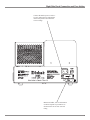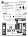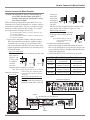
1
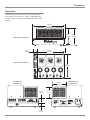
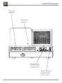
Stereo Power Amplifier
MC275
Owner’s Manual
McIntosh Laboratory, Inc.
2 Chambers Street Binghamton, New York
13903-2699 Phone: 607-723-3512
FAX: 607-724-0549
The lightning flash with arrowhead,
within an equilateral triangle, is
intended to alert the user to the
presence of uninsulated “dangerous voltage” within the product’s
enclosure that may be of sufficient
magnitude to constitute a risk of
electric shock to persons.
WARNING - TO REDUCE RISK OF
FIRE OR ELECTRICAL SHOCK, DO
NOT EXPOSE THIS EQUIPMENT TO
RAIN OR MOISTURE.
IMPORTANT SAFETY
INSTRUCTIONS!
PLEASE READ THEM BEFORE
OPERATING THIS EQUIPMENT.
1. Read these instructions.
2. Keep these instructions.
3. Heed all warnings.
4. Follow all instructions.
5. Do not use this apparatus near water.
6. Clean only with a dry cloth.
7. Do not block any ventilation openings. Install in
accordance with the manufacturer’s instructions.
8. Do not install near any heat sources such as radiators, heat registers, stoves, or other apparatus
(including amplifiers) that produce heat.
9. Do not defeat the safety purpose of the polarized
or grounding-type plug. A polarized plug has two
blades with one wider than the other. A grounding type plug has two blades and a third grounding prong. The wide blade or the third prong are
provided for your safety. If the provided plug does
not fit into your outlet, consult an electrician for
replacement of the obsolete outlet.
10. Protect the power cord from being walked on or
pinched particularly at plugs, convenience receptacles, and the point where they exit from the
apparatus.
2
The exclamation point within an
equilateral triangle is intended to
alert the user to the presence of important operating and maintenance
(servicing) instructions in the literature accompanying the appliance.
NO USER-SERVICEABLE PARTS
INSIDE. REFER SERVICING TO
QUALIFIED PERSONNEL.
To prevent the risk of electric shock, do not remove cover or
back. No user-serviceable parts inside.
11. Only use attachments/accessories specified by the
manufacturer.
12. Use only with the cart, stand, tripod, bracket, or
table specified by the manufacturer,
or sold with the apparatus. When a
cart is used, use caution when moving the cart/apparatus combination
to avoid injury from tip-over.
13. Unplug this apparatus during lightning storms or
when unused for long periods of time.
14. Refer all servicing to qualified service personnel. Servicing is required when the apparatus has
been damaged in any way, such as power-supply
cord or plug is damaged, liquid has been spilled or
objects have fallen into the apparatus, the apparatus has been exposed to rain or moisture, does not
operate normally, or has been dropped.
15. Do not expose this equipment to dripping or
splashing and ensure that no objects filled with liquids, such as vases, are placed on the equipment.
16. To completely disconnect this equipment from the
a.c. mains, disconnect the power supply cord plug
from the a.c. receptacle.
17. The mains plug of the power supply cord shall
remain readily operable.
18. Do not expose batteries to excessive heat such as
sunshine, fire or the like.
Thank You
Table of Contents
Your decision to own this McIntosh MC275 Stereo Power
Amplifier ranks you at the very top among discriminating
music listeners. You now have “The Best.” The McIntosh
dedication to “Quality,” is assurance that you will receive
many years of musical enjoyment from this unit.
Please take a short time to read the information in this
manual. We want you to be as familiar as possible with all
the features and functions of your new McIntosh.
Safety Instructions .......................................................................2
Thank You and Please Take a Moment .......................................3
Technical Assistance and Customer Service ..............................3
Table of Contents .........................................................................3
Important Information .................................................................3
Connector Information ................................................................4
Introduction .................................................................................4
Performance Features ..................................................................4
Dimensions ..................................................................................5
Installation of Tubes and Tube Cover ..........................................6
Location and Ventilation .............................................................7
Please Take A Moment
The serial number, purchase date and McIntosh Dealer
name are important to you for possible insurance claim or
future service. The spaces below have been provided for
you to record that information:
Serial Number: __________________________________
Connections:
Left Side Panel Connections .......................................................8
Right Side Panel Connection and Fuse Holder ...........................9
How to Connect for Stereo ........................................................10
How to Connect for Mono Parallel ............................................11
Left Side Panel Controls and Switches......................................12
Operation:
Purchase Date: __________________________________
How to Operate ..........................................................................13
Dealer Name: ___________________________________
Specifications ............................................................................14
Packing Instructions ..................................................................15
Additional Information:
Technical Assistance
If at any time you have questions about your McIntosh
product, contact your McIntosh Dealer who is familiar
with your McIntosh equipment and any other brands that
may be part of your system. If you or your Dealer wish
additional help concerning a suspected problem, you can
receive technical assistance for all McIntosh products at:
McIntosh Laboratory, Inc.
2 Chambers Street
Binghamton, New York 13903
Phone: 607-723-1545
Fax: 607-724-0549
Customer Service
If it is determined that your McIntosh product is in need of
repair, you can return it to your Dealer. You can also return
it to the McIntosh Laboratory Service Department. For
assistance on factory repair return procedure, contact the
McIntosh Service Department at:
General Information
1. Caution: To prevent electrical shock make sure that
the AC POWER CORD IS NOT CONNECTED TO THE MC275 when inserting
or removing Vacuum Tubes, as there are
hazardous voltages present at the pins of
the Tube Sockets.
2. When Vacuum Tubes are installed or removed make
sure to reattach the Tube Cover to the MC275 Chassis.
3. If the MC275 has been On, please allow the Hot Vacuum Tubes to cool first before removing them.
4. For additional connection information, refer to the
owner’s manual(s) for any component(s) connected to
the MC275.
5. The Main AC Power going to the MC275 and any other
McIntosh Component(s) should not be applied until all
the system components are connected together. Failure
to do so could result in malfunctioning of some or all of
the system’s normal operations.
McIntosh Laboratory, Inc.
2 Chambers Street
Binghamton, New York 13903
Phone: 607-723-3515
Fax: 607-723-1917
Copyright 2006 © by McIntosh Laboratory, Inc.
3
Connector Information, Introduction and Performance Features
Connector and Cable Information
Performance Features
XLR Connectors
Below is the Pin configuration for the XLR Balanced Input
Connectors on the MC275. Refer to the diagram for connection:
PIN 1: Shield/Ground
PIN 2: + Output
PIN 3: - Output
• Power Output
The MC275 consists of two separate power amplifier channels, each capable of 75 watts into 4, 8 or 16 ohm Loudspeakers in stereo. It may also be operated in mono at 150
watts into 2, 4, or 8 ohm Loudspeakers.
PIN 1
Introduction
PIN 3
PIN 2
Now you can take advantage of traditional McIntosh standards of excellence in the MC275 Stereo Power Amplifier.
Two 75 watt output channels will drive any high quality
Loudspeaker System to its ultimate performance. The
MC275 reproduction is sonically transparent and absolutely accurate. The McIntosh Sound is “The Sound of the
Music Itself.”
• Bifilar Wound Transformers and Output Circuit
The Power Output Sections utilize the famous McIntosh
Patented Unity Coupled Circuit with a Bifilar Wound
Output Transformer for low distortion, extended frequency
response and cool operating output tubes.
• Balanced and Unbalanced Inputs
Balanced connections guard against induced noise and allow long cable runs without compromising sound quality.
• Gold Plated Connectors and Tube Socket Contacts
Gold Plated Input Jacks and Output Binding Posts provide
trouble free connections. Ceramic tube sockets with gold
plated contacts provide protection from atmospheric contamination. Output Tube Sockets include Air-Pipe cooling
at their bases.
• Super Mirror Chassis Finish
The famous McIntosh Stainless Steel Chassis with Super
Mirror Finish ensures the pristine beauty of the MC275
will be retained for many years.
4
Dimensions
Dimensions
The following dimensions can assist in determining the
best location for your MC275. There is additional information on page 7 pertaining to installing the MC275 into
cabinets.
16-1/2"
41.91cm
7-7/8"
20.00cm
Front View of the MC275
1-3/4"
8-1/4"
20.96cm
13-5/8"
4.45cm
34.61cm
Top View of the MC275
12"
30.48cm
Left Side View
of the MC275
5-9/16"
14.13cm
1-3/4"
4.45cm
Right Side View
of the MC275
4-3/8"
11.11cm
1-1/4"
3.18cm
5
Installation of Tubes and Tube Cover
Caution: To prevent electrical shock make sure that
the AC POWER CORD IS NOT CONNECTED TO THE MC275 when inserting or
removing Tubes, as there are hazardous voltages present at the pins of the Tube Sockets.
Your MC275 has gone through an extensive series of
performance tests during the manufacturing process. The
MC275 is supplied with the actual Tubes that were used
to test and confirm the performance of this amplifier. To
protect the Vacuum Tubes from possible shipping damage,
they are packed in four layers of foam and placed into the
Tube Cover. It is secured to the MC275 Chassis.
Tinnerman Clip Fasteners
Tube Cover
Note: Gloves or a soft cloth will prevent “ fingerprinting” of
the Tubes during their installation.
1. Orient the MC275 so the Front Panel is facing you.
2. Remove the Tube Cover from the MC275 Chassis by
lifting up on both sides. Refer to figure 1.
3. Orient the Tube Cover with the top side down so the
foam containing the Tubes is accessible. Refer to figure 2.
4. Remove the first layer of foam to expose the Tubes.
Refer to figure 3.
5. Carefully remove the Tubes from the remaining pieces
of foam and temporarily place them in a safe location.
6. Remove the remaining foam from the Tube Cover and
retain all four pieces for possible future use.
The MC275 Chassis has nomenclature screened on it to
specify both the circuit location and Tube Type for each
channel. Refer to figure 4.
Figure 1
Tube Cover with
Layers of Foam
and Tubes inside
Figure 2
Small Signal Tubes
Power Output Tubes
Note: It is extremely important to insert the Tubes in the
correct location.
Power Output Tubes:
1. Orient the Chassis so the Front Panel of the Amplifier is
facing you.
2. Locate a KT88 or 6550 Power Output Tube.
3. On the top left side of the amplifier, locate the Tube
Socket that has the nomenclature V8 KT88/6550 next
to it on the chassis.
4. Orient the Tube so the key on the base of the Tube
is aligned with the corresponding key on the Tube
Socket.
5. Carefully insert the Tube into the socket until the base
of the Tube is fully seated in the Tube Socket.
6. Repeat the above the steps for the remaining 4 Power
Output Tubes.
There are two different types of Small Signal Tubes
(12AX7A and 12AT7) used in each channel. Tube type can
be found on the outside of the Tube. The MC275 will not
function if they are inserted into the wrong socket.
6
Figure 3
V8 KT88/6550 Tube
V1 12AX7A Tube
Figure 4
Installation of Tubes, Tube Cover, Location and Ventilation
Small Signal Tubes:
1. Locate a 12AX7A Tube.
2. On the top left side of the amplifier, locate the Tube
Socket that has the nomenclature V1 12AX7A next to it
on the chassis. Refer to figure 4 and 5.
3. Orient the Tube so the area where no pins are located on
the base of the Tube is aligned with the corresponding
area on the Tube Socket.
4. Carefully insert the Tube into the socket until the base
of the Tube is fully seated in the Tube Socket.
5. Repeat the above steps for the remaining two 12AX7A
Tubes at locations V2 and V5.
6. Locate a 12AT7 Tube.
7. On the top center of the amplifier, locate the Tube
Socket that has the nomenclature V3 12AT7A next to it
on the chassis.
8. Insert the Tube, following the same procedure as in
steps 3 and 4.
9. Repeat steps 6-9 for the remaining three 12AT7 Tubes
at locations V4, V6 and V7.
Caution: To prevent electrical shock make sure the
MC275 Tube Cover is installed before connecting the AC Power Cord.
Before operating the MC275, locate the previously removed Tube Cover and perform the following steps:
Installing the Tube Cover:
1. The Tube Cover has a wide opening along one side of
its longer dimension. Orient this wide opening so it is
facing towards the three large transformers.
2. Carefully place the Tube Cover onto the MC275 while
at the same time aligning the two chassis mounted ball
studs with the Tinnerman Clips in the cover. Refer to
figure 6.
KT88/6550
Tubes
Figure 5
12AX7A
Tubes
12AT7
Tubes
12AX7A
Tube
12AT7
Tubes
Ball Stud Fasteners
Figure 6
Location and Ventilation
The MC275 can be placed upright on a table or shelf,
standing on its four feet. It also can be installed in a piece
of furniture of your choice. Do not install the MC275
directly above a heat generating component. Adequate
ventilation extends the trouble free life of the MC275. The
suggested minimum space for operating the MC275 is 22
inches (55.88cm) in width, 18 inches (45.72cm) depth, and
21 inches (53.34cm) in height. Always allow air to flow
through the ventilation holes on the bottom of the amplifier
and a means for the warm air to escape at the top. If the
MC275 is installed in a cabinet, a quiet running ventilation
fan can be a definite asset in maintaining the coolest possible operating temperature. Refer to figure 7.
Warm Air
Cool Air
Figure 7
7
Left Side Panel Connections
LEFT OUTPUT
Connections for
loudspeakers
RIGHT OUTPUT
Connections for
loudspeakers
BALANCED INPUTS
for audio cables from a
preamplifier or control
center audio outputs
UNBALANCED INPUTS
for audio cables from a
preamplifier or control
center audio outputs
8
Right Side Panel Connection and Fuse Holder
Connect the MC275 power cord to a
live AC outlet. Refer to information
on the back panel to determine the
correct voltage
Main Fuse holder, refer to information
on the back panel of your MC275 to
determine the correct fuse size and
rating
9
How to Connect for Stereo
How to Connect for Stereo
Caution: The supplied AC Power Cord should not be
connected to the Rear Panel of the MC275
Amplifier until after the Loudspeaker Connections have been made.
When connecting Loudspeakers to the MC275 it is very
important to use cables of adequate size, so there is little to
no power loss in the cables. The size is specified in Gauge
Numbers or AWG (American Wire Gauge). The smaller
the Gauge number, the larger the wire size:
If your loudspeaker cables are 50 feet (38.1m) or less,
use at least 14 Gauge.
If your loudspeaker cables are 100 feet (76.2m) or less,
use at least 12 Gauge.
1. Prepare the Loudspeaker Hookup Cables that attach to
the Amplifier by choosing one of the methods below:
Bare wire cable ends:
Carefully remove sufficient insulation from the
cable ends, refer to figures 1, 2 & 3. If the cable is
stranded,
carefully
twist the
strands
Figure 2
Figure 3
together as
Figure 1
tightly as
possible.
Note: If desired, the twisted ends can be tinned with
solder to keep the strands together, or attach
spade lug and/or banana connector.
Spade lug or prepared wire connection:
Insert the spade lug connector or prepared section
of the cable end into the terminal side access hole,
and tighten
the terminal
cap until
the cable
is firmly
clamped into the terminal so the wires cannot slip
out. Refer to figures 4, 5 & 6.
Banana plug connection:
Insert the banana plug into the hole at the top of the
terminal. Refer to figure 7.
Note: Banana Plugs are for use
in the United States and
Canada only.
2. Connect the loudspeaker hookup cables to the output terminals that match
the impedance of your loudspeakers,
being careful to observe the correct polarities.
3. Connect the MC275 Power Cord to a live AC outlet.
McIntosh Preamplifier
75 WATTS
T630maAL 250V
McIntosh Loudspeaker
McIntosh Loudspeaker
McIntosh MC275 (Partial View)
10
How to Connect for Mono Parallel
How to Connect for Mono Parallel
Caution: The supplied AC Power Cord should not be
connected to the Rear Panel of the MC275
Amplifier until after the Loudspeaker Connections have been made.
When connecting Loudspeakers to the MC275 it is very
important to use cables of adequate size, so there is little to
no power loss in the cables. The size is specified in Gauge
Numbers or AWG (American Wire Gauge). The smaller
the Gauge number, the larger the wire size:
into the terminal side
access hole,
and tighten
the terminal
cap until
the cable is firmly clamped into the terminal so the
wires cannot slip out. Refer to figures 4, 5 & 6.
Banana plug connection:
Insert the banana plug into the hole
at the top of the terminal. Refer to
figure 7.
If your loudspeaker cables are 50 feet (38.1m) or less,
use at least 14 Gauge.
If your loudspeaker cables are 100 feet (76.2m) or less,
use at least 12 Gauge.
1. Prepare the Loudspeaker Hookup Cable and Jumper
Wires for connection to the Power Amplifier Output
Terminals; two 5-1/4 inch (13.34 cm) Jumper Wires
and one Loudspeaker Hookup Cable cut to the desired
length. Prepare the cable and wires by choosing one of
the methods below:
Bare wire cable ends:
Carefully remove sufficient insulation from the cable
ends, refer to
figures 1, 2 &
3. If the cable
is stranded,
carefully
Figure 2
Figure 3
Figure 1
twist the
strands together as tightly as possible.
Note: Banana Plugs are for use
in the United States and
Canada only.
2. Connect the loudspeaker hookup
cables to the output terminals that match the impedance of your loudspeakers, being careful to observe the
correct polarities. Refer to the Mono (Parallel) Hookup
Connections Chart below.
3. Connect the MC275 Power Cord to a live AC outlet.
Mono (Parallel) Hookup Connections
Loudspeaker
Impedance
Loudspeaker Negative
(-) Connection
Loudspeaker Positive
(+) Connection
2Ω (Ohm)
Left and Right Output
COMmon Connection
Left and Right Output
4Ω Connection
4Ω (Ohm)
Left and Right Output
COMmon Connection
Left and Right Output
8Ω Connection
8Ω (Ohm)
Left and Right Output
COMmon Connection
Left and Right Output
16Ω Connection
Note: If desired, the twisted ends can be tinned with
solder to keep the strands together,
McIntosh Loudspeaker
or attach spade lug and/or banana
connector.
Spade lug or prepared wire connection:
Insert the spade lug connector or
prepared section of the cable end
McIntosh Preamplifier
75 WATTS
T630maAL 250V
Jumper
McIntosh MC275 (Partial View)
Jumper
11
Left Side Panel Controls and Switches
MODE Switch selects
MONO (Parallel) or
STEREO Modes of
operation
Power Switch turns all
AC power On or Off
INPUTS Switch selects between the
BALanced or UNBALanced Inputs
12
How to Operate the MC275
How to Operate the MC275
Power On and Off
Press the POWER switch to the ON position and sound
will be heard from the Loudspeakers when the tubes have
reached their operating temperature.
POWER
The amount of time it takes is dependent upon the temperature of the OFF
ON
Tubes. Press the POWER Switch to
the Off position to stop amplifying
Figure 8
the audio signal. Refer to figure 8.
Note: If the MC275 is connected to a McIntosh Preamplifier,
Control Center or A/V Center, the addition of a McIntosh Power Controller such as a PC4 will allow the
MC275 to switch On and Off automatically.
Mode Switch
The MODE Switch, which is located on the Left Side Panel
of the MC275, allows selection of
MODE
either Stereo or Mono (Parallel)
Modes of Operation. Refer to figure
MONO
STEREO
9 and pages 10 and 11 for connection information.
Figure 9
Input Switch
When BALANCED Input Connections are used, place the
MC275 INPUT Switch to the BALINPUTS
anced position. If UNBALANCED
connections are used, place the
INPUT Switch to the UNBALanced
BAL
UNBAL
position. Refer to figure 10.
Figure 10
13
Specifications
Specifications
Power Output Stereo
Minimum sine wave continuous average power output per
channel, both channels operating is:
75 watts into 4, 8 or 16 ohm load
Tube Compliment
3 - 12AX7A Inputs and Phase Inverters
4 - 12AT7 Voltage Amplifier and Drivers
4 - KT88/6550 Power Output
Power Output Mono (Parallel)
Minimum sine wave continuous average power output is:
150 watts into 2 ohm, 4 ohm or 8 ohm load
Power Requirements
100 Volts, 50/60Hz at 3.6 amps
110 Volts, 50/60Hz at 3.6 amps
120 Volts, 50/60Hz at 3.6 amps
220 Volts, 50/60Hz at 1.8 amps
230 Volts, 50/60Hz at 1.8 amps
240 Volts, 50/60Hz at 1.8 amps
Output Load Impedance
4, 8, or 16 ohm (Stereo Mode)
2, 4, or 8 ohm (Mono Mode)
Rated Power Band
20Hz to 20,000Hz
Note: Refer to the right side panel of the MC275 for the correct
voltage.
Total Harmonic Distortion
Maximum Total Harmonic Distortion at any power level
from 250 milliwatts to rated power output is 0.5%
Overall Dimensions
Width is 16-1/2 inches (41.91cm)
Height is 8-1/4 inches (20.96cm) including feet
Depth is 12 inches (30.48cm)
Intermodulation Distortion
Maximum Intermodulation Distortion if instantaneous
peak output per channel does not exceed twice the rated
output, for any combination of frequencies from 20Hz to
20,000Hz, with both channels operating is 0.5%
Weight
67 pounds (30.5kg) net, 75 pounds (34.lkg) in shipping
carton
A-Weighted Signal To Noise Ratio
100dB
Frequency Response
+0, -0.5dB from 20Hz to 20,000Hz
+0, -3dB from 10Hz to 70,000Hz
Sensitivity
1.2 Volt unbalanced inputs
2.5 Volt balanced inputs
Input Impedance
90,000 ohms unbalanced inputs
180,000 ohms balanced inputs
Wide Band Damping Factor
Greater than 14
14
Packing Instructions
Packing Instructions
In the event it is necessary to repack the equipment for
shipment, the equipment must be packed exactly as described and shown below.
The MC275 Vacuum Tubes must be removed from the
Amplifier Tube Sockets and placed into the openings of the
four layer foam packing material. The foam with the tubes
located inside are placed into the Amplifier Tube Cover
and secured to the Chassis. Failure to do this will result in
damage to the Vacuum Tubes and possibly the MC275.
It is very important that the four plastic feet are attached to the bottom of the equipment. This will ensure the
proper equipment location on the bottom pad. Failure to do
this will result in shipping damage.
Use the original shipping carton and interior parts only
if they are all in good serviceable condition. If a shipping
carton or any of the interior part(s) are needed, please call
or write Customer Service Department of McIntosh Laboratory. Please see the Part List for the correct part numbers.
Quantity
1
2
Part Number
034005
033718
Description
Shipping carton outside
Foam Pad (side)
2
2
034266
034265
Foam pack tube (ends)
Foam pack tube (inside
with tube cutouts)
1
1
1
1
1
1
1
034006
033707
033712
033704
033705
033706
033711
Shipping carton inside
Top pad
Foam pad (tube cover)
Bottom pad
Front pad
Rear pad
Side pads
4
017862
Plastic foot
15
McIntosh Laboratory, Inc.
2 Chambers Street
Binghamton, NY 13903
The continuous improvement of its products is the
policy of McIntosh Laboratory Incorporated who
reserve the right to improve design without notice.
Printed in the U.S.A.
McIntosh Part No. 04099600