1
Basic version
Advanced version
AV Surround Receiver
Owner’s Manual
Information
SR6006
nSAFETY PRECAUTIONS
CAUTION:
TO REDUCE THE RISK OF ELECTRIC SHOCK, DO NOT REMOVE
COVER (OR BACK). NO USER-SERVICEABLE PARTS INSIDE.
REFER SERVICING TO QUALIFIED SERVICE PERSONNEL.
The exclamation point within an equilateral triangle is intended
to alert the user to the presence of important operating
and maintenance (servicing) instructions in the literature
accompanying the appliance.
WARNING:
TO REDUCE THE RISK OF FIRE OR ELECTRIC SHOCK, DO NOT
EXPOSE THIS APPLIANCE TO RAIN OR MOISTURE.
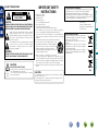
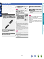
HOT SURFACE. DO NOT TOUCH.
Hot
surface
mark
The top surface over the internal heat sink may become hot
when operating this product continuously.
Do not touch hot areas, especially around the “Hot surface
mark” and the top panel.
13.Refer all servicing to qualified service personnel.
Servicing is required when the apparatus has been damaged in any way,
such as power-supply cord or plug is damaged, liquid has been spilled or
objects have fallen into the apparatus, the apparatus has been exposed to
rain or moisture, does not operate normally, or has been dropped.
14.Batteries shall not be exposed to excessive heat such as sunshine, fire or
the like.
CAUTION:
To completely disconnect this product from the mains, disconnect the plug
from the wall socket outlet.
The mains plug is used to completely interrupt the power supply to the unit
and must be within easy access by the user.
I
marantz Europe
A division of D&M Europe B.V.
Beemdstraat 11, 5653 MA Eindhoven,
The Netherlands
A NOTE ABOUT RECYCLING:
This product’s packaging materials are recyclable and can
be reused. Please dispose of any materials in accordance
with the local recycling regulations.
When discarding the unit, comply with local rules or
regulations.
Batteries should never be thrown away or incinerated
but disposed of in accordance with the local regulations
concerning battery disposal.
This product and the supplied accessories, excluding the
batteries, constitute the applicable product according to
the WEEE directive.
Information
CAUTION:
Read these instructions.
Keep these instructions.
Heed all warnings.
Follow all instructions.
Do not use this apparatus near water.
Clean only with dry cloth.
Do not block any ventilation openings.
Install in accordance with the manufacturer’s instructions.
Do not install near any heat sources such as radiators, heat registers,
stoves, or other apparatus (including amplifiers) that produce heat.
9. Protect the power cord from being walked on or pinched particularly at
plugs, convenience receptacles, and the point where they exit from the
apparatus.
10. Only use attachments/accessories specified by the manufacturer.
11. Use only with the cart, stand, tripod, bracket, or table
specified by the manufacturer, or sold with the apparatus.
When a cart is used, use caution when moving the cart/
apparatus combination to avoid injury from tip-over.
12. Unplug this apparatus during lightning storms or when
unused for long periods of time.
We declare under our sole responsibility that this product, to which this
declaration relates, is in conformity with the following standards:
EN60065, EN55013, EN55020, EN61000-3-2 and EN61000-3-3.
Following the provisions of Low Voltage Directive 2006/95/EC and EMC
Directive 2004/108/EC, the EC regulation 1275/2008 and its frame work
Directive 2009/125/EC for Energy-related Products (ErP).
Advanced version
The lightning flash with arrowhead symbol, within an equilateral
triangle, is intended to alert the user to the presence of
uninsulated “dangerous voltage” within the product’s enclosure
that may be of sufficient magnitude to constitute a risk of
electric shock to persons.
1.
2.
3.
4.
5.
6.
7.
8.
• DECLARATION OF CONFORMITY
Basic version
CAUTION
RISK OF ELECTRIC SHOCK
DO NOT OPEN
IMPORTANT SAFETY
INSTRUCTIONS
nCAUTIONS ON INSTALLATION
nNOTES ON USE
z
z
z
z
Wall
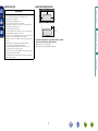
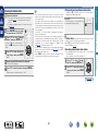
zzFor proper heat dispersal, do not install this unit in a confined
space, such as a bookcase or similar enclosure.
•More than 0.3 m is recommended.
•Do not place any other equipment on this unit.
Advanced version
•Avoid high temperatures.
Allow for sufficient heat dispersion when installed in a rack.
•Handle the power cord carefully.
Hold the plug when unplugging the cord.
•Keep the unit free from moisture, water, and dust.
•Unplug the power cord when not using the unit for long periods of time.
•Do not obstruct the ventilation holes.
•Do not let foreign objects into the unit.
•Do not let insecticides, benzene, and thinner come in contact with the unit.
•Never disassemble or modify the unit in any way.
•Ventilation should not be impeded by covering the ventilation openings
with items, such as newspapers, tablecloths or curtains.
•Naked flame sources such as lighted candles should not be placed on
the unit.
•Observe and follow local regulations regarding battery disposal.
•Do not expose the unit to dripping or splashing fluids.
•Do not place objects filled with liquids, such as vases, on the unit.
•Do not handle the mains cord with wet hands.
•When the switch is in the OFF (STANDBY) position, the equipment is not
completely switched off from MAINS.
•The equipment shall be installed near the power supply so that the power
supply is easily accessible.
Basic version
WARNINGS
Information
II
Thank you for purchasing this marantz product. To ensure proper operation, please read this owner’s manual carefully before using the product.
After reading them, be sure to keep them for future reference.
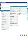
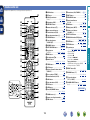
Contents
Getting started···············································································1
Accessories···················································································2
Features·························································································2
Cautions on handling·····································································3
Speaker installation/connection (Advanced)····························55
Install···························································································55
Connect·······················································································57
Set up speakers···········································································64
Connections (Advanced connection)·········································66
Connecting the remote control connectors·································66
Connecting the RS-232C connector············································67
Connecting the DC OUT (TRIGGER OUT) jacks··························67
Playback (Advanced operation)··················································68
Convenient functions···································································68
Playback in ZONE2/ZONE3 (Separate room) ···························79
Audio output················································································79
Video output················································································80
Playback·······················································································80
Sleep timer function····································································81
How to make detailed settings···················································82
Menu map···················································································82
Examples of menu screen displays·············································83
Examples of menu·······································································84
Inputting characters ····································································85
SOURCE SELECT········································································87
AUDIO/VIDEO ADJUST·······························································94
SYSTEM SETUP········································································100
INFORMATION··········································································116
Other settings·············································································117
Remote control settings····························································117
Operating the connected devices by remote control unit·····118
Operating AV devices································································118
Registering preset codes···························································119
Operating devices······································································121
Operating learn function····························································123
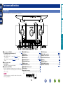
Part names and functions·························································126
Front panel·················································································126
Display·······················································································127
Rear panel··················································································128
Remote control unit···································································129
Other information······································································131
Trademark information·······························································131
Surround····················································································132
Relationship between video signals and monitor output···········136
Explanation of terms··································································138
Troubleshooting·········································································141
Resetting the microprocessor···················································144
Specifications·············································································145
1
Information
Connections····················································································5
Important information····································································5
Connecting an HDMI-compatible device·······································7
Connecting a TV··········································································10
Connecting a Blu-ray Disc player·················································11
Connecting a DVD player·····························································12
Connecting a set-top box (Satellite tuner/cable TV)·····················12
Connecting a video cassette recorder·········································13
Connecting a digital camcorder···················································13
Connecting an iPod or USB memory device to the USB port······14
Connecting an antenna································································15
Connecting a CD player·······························································16
Connecting a record player··························································16
Connecting a wireless receiver (RX101)······································17
Connect a device that has a multichannel output terminal··········17
Connecting a external power amplifier········································18
Connecting to a home network (LAN)·········································19
Settings·························································································20
Set up speakers (Audyssey® Auto Setup)··································20
Making the network settings (Network Setup)····························26
Playback (Basic operation)··························································27
Important information··································································27
Playing a Blu-ray Disc player/DVD player·····································29
Playing a CD player······································································29
Playing an iPod············································································30
Playing a USB memory device·····················································32
Tuning in radio stations································································34
Playing a network audio·······························································38
Selecting a listening mode (SURROUND MODE)·····················50
Selecting a listening mode··························································50
Information············································································125
Advanced version
Basic version·············································································4
Advanced version ·······························································54
Basic version
Getting started
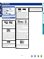
Accessories
Features
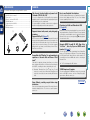
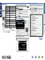
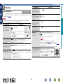
qGetting Started......................................................................... 1
wCD-ROM (Owner’s manual)..................................................... 1
ePower cord............................................................................... 1
rRemote control unit (RC014SR)............................................... 1
tR03/AAA batteries.................................................................... 2
ySetup microphone (ACM1H).................................................... 1
uAM loop antenna...................................................................... 1
iFM indoor antenna................................................................... 1
y
Supports internet radio, music, and photograph
streaming
Supports AirPlay® (vpage 71)
r
u
The unit is equipped with a power amplifier that reproduces
highfidelity sound in surround mode with equal quality and power
for all channels, true to the original sound.
The power amplifier circuit adopts a discrete-circuit configuration
that achieves high-quality surround sound reproduction.
i
When connected to a network, this unit can play audio files and still
images such as photographs that are stored on your computer. You
can also listen to internet radio and a host of other online music
sources that use network technology. This unit also supports
AirPlay that lets you stream your music library from an iPhone,
iPad, iPod touch or iTunes.
“Wizz App” is application software that allows you to perform
basic operations with an iPhone or iPod touch such as turning the
unit ON/OFF, controlling the volume, and switching the source.
z1 Download “Wizz App” from iTunes® App Store. The unit
needs to be connected to a LAN and the iPhone/iPod touch
needs to be connected to the same network by Wi-Fi (wireless
LAN).
Setup Wizard, providing easy-to-follow setup
instructions
First select the language when prompted. Then simply follow the
instructions displayed on the TV screen to set up the speakers,
network, etc.
2
This unit is equipped with an easy to see “Graphical User Interface”
that uses menu displays and levels. The use of level displays
increases operability of the this unit.
Direct play for iPod® and iPhone® via USB
(vpage 14)
Music data from an iPod can be played back if you connect the USB
cable supplied with the iPod via the USB port of this unit, and also
an iPod can be controlled with the remote control unit for this unit.
When an iPod is connected, merely pressing 21 starts playback
of music from the iPod.
Supports HDMI 1.4a with 3D, ARC, Deep Color,
“x.v.Color” , Auto Lip Sync and HDMI control
function (vpage 7)
This unit can output 3D video signals input from a Blu-ray Disc
player to a TV that supports a 3D system. This unit also supports
the ARC (Audio Return Channel) function, which reproduces TV
sound with this unit via an HDMI cable used for connecting the
unit and a TVz2.
z2 The TV should support the ARC function.
7-HDMI inputs and 2-outputs
The unit is equipped with 7 HDMI input connectors for connecting
devices with HDMI connectors, such as a Blu-ray Disc player,
game machine, HD video camera, etc.
vSee overleaf
Information
Compatible with “Wizz App” for performing basic
operations of the unit with an iPhone or iPod
touchz1
Easy to use, Graphical User Interface
Advanced version
e
Fully discrete, identical quality and power for all
7 channels (110 W x 7ch, 8 Ω)
Basic version
Check that the following parts are supplied with the product.
Features
This unit is equipped with two HDMI MONITOR outputs. You can
connect one output to a projector and the other output to a TV for
simultaneous signal outputs.
All sources are up-scaled to 1080p
High definition audio support
The unit is equipped with a decoder which supports high-quality
digital audio format for Blu-ray Disc players such as Dolby TrueHD,
DTS-HD Master Audio, etc.
This unit is equipped with Audyssey DSX™ processor. By
connecting front height speakers to this unit and playing back
through Audyssey DSX™, you can experience a more powerful
playback expression in the height audio range. By connecting front
wide speakers, you can experience a more powerful playback
expression in the wide audio range.
M-XPort (marantz-eXtension Port) (vpage 17)
•Power is supplied to some of the circuitry even when the unit is
set to the standby mode. When going on vacation or leaving home
for long periods of time, be sure to unplug the power cord from the
power outlet.
•About condensation
If there is a major difference in temperature between the inside of
the unit and the surroundings, condensation (dew) may form on
the operating parts inside the unit, causing the unit not to operate
properly.
If this happens, let the unit sit for an hour or two with the power
turned off and wait until there is little difference in temperature
before using the unit.
•Cautions on using mobile phones
Using a mobile phone near this unit may result in noise. If that
occurs, move the mobile phone away from this unit when it is in use.
•Moving the unit
Turn off the power and unplug the power cord from the power
outlet. Next, disconnect the connection cables to other system units
before moving the unit.
•About care
•Wipe the cabinet and control panel clean with a soft cloth.
•Follow the instructions when using a chemical cleaner.
•Benzene, paint thinner or other organic solvents as well as
insecticide may cause material changes and discoloration if brought
into contact with the unit, and should therefore not be used.
This unit is equipped with the M-XPort, a marantz original innovation
that provides outstanding expandability. You can connect the
Wireless Receiver RX101 (sold separately) to this port.
3
Information
Audyssey DSX™
•Before turning the power on
Check once again that all connections are correct and that there are
no problems with the connection cables.
Advanced version
The unit is provided with an HDMI video up-scaling function that
converts an analog video signal input to the unit to a 1080p (HD
resolution) signal and supplies it to a TV via the HDMI connector.
This enables the unit and a TV connected with a single HDMI cable
and any video source to be reproduced precisely with HD level of
quality.
Cautions on handling
Basic version
Simultaneous playback on two HDMI channels
Basic version
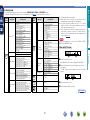
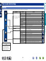
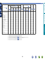
Here, we explain the connections and basic operation methods for this unit.
Advanced version
F Connections vpage 5
F Settings vpage 20
F Playback (Basic operation) vpage 27
F Selecting a listening mode (SURROUND MODE) vpage 50
–
Playback
vpage 8, 11
Connection
vpage 29
Playback
vpage 8, 13
Connection
–
Playback
Connection
vpage 8, 11
Playback
vpage 29
Connection
vpage 16
Playback
vpage 29
Connection
Playback
vpage 8, 12
–
Connection
vpage 14
Connection
vpage 14
Playback
vpage 30
Playback
vpage 32
Connection
vpage 13
vpage 8
Connection
–
Playback
vpage 16
Connection
–
Playback
vpage 17
Connection
–
Playback
Playback
Connection
vpage 15
Playback
vpage 34
Connection
vpage 19
Playback
vpage 38
For speaker connections, see page 57, C page 6 “Connecting the speakers”.
4
–
Information
vpage 8, 10
Connection
Basic version
Basic
version
Basic version
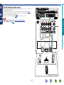
Connections
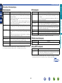
Important information
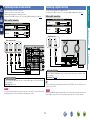
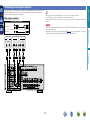
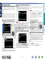
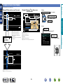
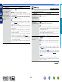
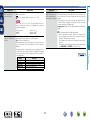
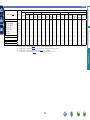
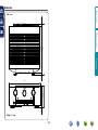
Converting input video signals for output (Video conversion function)
This unit is equipped with three types of video input connectors (HDMI, Component video and video) and three types of video output connectors
(HDMI, Component video and video).
Use the connectors corresponding to the devices to be connected.
This function automatically converts various formats of video signals input to this unit into the formats used to output the video signals from
this unit to a monitor.
GFlow of video signals for MAIN ZONEH
NOTE
This unit
Video device
Monitor (TV)
Output
Input
(IN)
Output
(MONITOR OUT)
HDMI connector
HDMI connector
HDMI
connector
HDMI connector
Component video
connectors
Component video
connectors
Component video
connectors
Component video
connectors
Video connector
Video connector
Video connector
Input
Information
•Do not plug in the power cord until all connections have been
completed (When the Setup wizard is running, follow the instructions
in the Setup wizard screen for making connections.).
•When running the Setup wizard, turn off the power supply of
connected devices.
•When making connections, also refer to the operating instructions of
the other devices being connected.
•Be sure to connect the left and right channels properly (left with left,
right with right).
•Do not bundle power cords together with connection cables. Doing
so can result in noise.
Video connector
: when 480i/576i signals are input
vSee overleaf
5
Advanced version
•Make connections as follows before using this unit. Select an
appropriate connection type according to the devices to be
connected.
•You may need to make some settings on this unit depending
on the connection method. Refer to each description for more
information.
•Select the cables (sold separately) according to the devices
being connected.
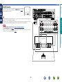
Important information
This unit
Video device
Output
Video connector
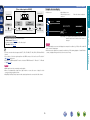
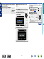
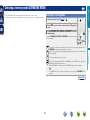
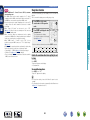
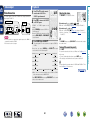
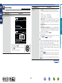
•Status display screen
When the input source is
switched.
When the volume is adjusted.
AUDIO/VIDEO ADJUST
Output
(MONITOR OUT)
Input
Video connector
Video connector
Audio Adjust
Picture Adjust
AUTO
Adjust various audio and video parameters
in Set as Necessary
SOURCE
SURROUND
BD
DTS SURROUND
-52.0dB
Status display: The operating status appears briefly on the screen
when the input source is switched or the volume is
changed.
•Set when not using the video conversion function.
“Video Convert” (vpage 90)
•Set when changing the resolution of the video signal.
“Resolution” (vpage 90)
NOTE
Advanced version
Video connector
Input
(IN)
•Menu screen
Monitor (TV)
Basic version
Examples of screen display
GFlow of video signals for ZONE2H
•The status display screen cannot be displayed at a computer’s resolution (e.g. VGA) or while certain 3D
video contents is being played.
•When the menu is operated on a computer’s resolution (e.g. VGA) or during playback of certain 3D video
content, the playback image switches to the menu screen image.
Information
•The video conversion function supports the NTSC, PAL, SECAM, NTSC 4.43, PAL-N, PAL-M and PAL-60
formats.
•The resolution of the video signal output from the HDMI connector of this unit is set in “Resolution”
(vpage 90) in the menu.
•Resolutions of HDMI-compatible TVs can be checked at “HDMI Information” – “Monitor 1” or “Monitor
2” (vpage 116).
NOTE
•HDMI signals cannot be converted into analog signals.
•When a non-standard video signal from a game machine or some other source is input, the video
conversion function might not operate.
•480p/576p/1080i/720p/1080p component video input signals cannot be converted into Video format.
6
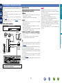
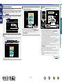
Connecting an HDMI-compatible device
About 3D function
HDMI function
This unit supports input and output of 3D (3 dimensional) video signals of HDMI 1.4a.
To play back 3D video, you need a TV and player that provide support for the HDMI1.4a 3D function and
a pair of 3D glasses.
This unit supports the following HDMI functions:
•3D
•Deep Color (vpage 138)
•Auto Lip Sync (vpage 104, 138)
•“x.v.Color”, sYCC601 color, Adobe RGB color, Adobe YCC601 color (vpage 138, 140)
•High definition digital audio format
•ARC (Audio Return Channel)
•Content Type
•CEC (HDMI control)
Basic version
You can connect up to nine HDMI-compatible devices (7-inputs/2-outputs) to the unit.
NOTE
Copyright protection system
In order to play back digital video and audio such as BD-Video or DVD-Video via HDMI connection, both
this unit and TV or the player need to support the copyright protection system known as HDCP (Highbandwidth Digital Content Protection System). HDCP is copyright protection technology comprised of
data encryption and authentication of the connected AV devices. This unit supports HDCP.
•If a device that does not support HDCP is connected, video and audio are not output correctly. Read
the owner’s manual of your television or player for more information.
Advanced version
•When playing back 3D video, refer to the instructions provided in the manual of your playback device
together with this manual.
•When playing back 3D video content, the menu screen or status display screen can be superimposed
over the image. However, the menu screen or status display screen cannot be superimposed over
certain 3D video content.
•If 3D video with no 3D information is input, the menu screen and status display on this unit are displayed
over the playback video.
•If 2D video is converted to 3D video on the television, the menu screen and status display on this unit
are not displayed correctly. To view the menu screen and status display on this unit correctly, turn the
television setting that converts 2D video to 3D video off.
About ARC (Audio Return Channel) function
The Audio Return Channel in HDMI 1.4a enables a TV, via a single HDMI cable, to send audio data “upstream”
to this unit.
NOTE
•To enable the ARC function, set “HDMI Control” – “Control” to “ON” (vpage 105).
•The ARC function cannot use the HDMI MONITOR 1 and HDMI MONITOR 2 connectors simultaneously.
Perform the “Control Monitor” setting in accordance with a TV that supports the ARC function and HDMI
MONITOR connector in this unit.
•When connecting a TV that does not support the ARC function, a separate connection using an audio
cable is required. In this case, refer to “Connecting a TV” (vpage 10) for the connection method.
HDMI control function (vpage 68)
This function allows you to operate external devices from the unit and operate the unit from external
devices.
About Content Type
NOTE
HDMI 1.4a enables simple, automated picture setting selection with no user intervention.
•The HDMI control function may not work depending on the device it is connected to and its settings.
•You cannot operate a TV or Blu-ray Disc player/DVD player that is not compatible with the HDMI control
function.
NOTE
To enable the Content Type, set “Video Mode” to “Auto” (vpage 89).
vSee overleaf
7
Information
About HDMI cables
•When a device supporting Deep Color is connected, use a cable compatible with “High Speed HDMI
cable” or “High Speed HDMI cable with Ethernet”.
•When the ARC function is used, connect a device with a ”Standard HDMI cable with Ethernet” or “High
Speed HDMI cable with Ethernet” for HDMI 1.4a.
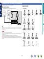
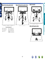
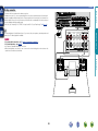
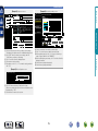
Connecting an HDMI-compatible device
Cables used for connections
Audio and video cable (sold separately)
Basic version
Digital
camcorder 1
HDMI
OUT
HDMI cable
•This interface allows transfer of digital video signals and digital audio signals over a single HDMI cable.
DVD
player
Set-top
box
Video
cassette
recorder
HDMI
OUT
HDMI
OUT
HDMI
OUT
HDMI
OUT
Game
Digital
console camcorder 2
HDMI
OUT
HDMI
OUT
TV 1
TV 2
HDMI
IN
HDMI
IN
GFront panelH
NOTE
•When you use the HDMI control function, set “HDMI Control” – “Control” (vpage 105) to “ON” and
set the HDMI MONITOR connector that you want to operate by the HDMI control function in “Control
Monitor”.
•The audio signal from the HDMI output connector (sampling frequency, number of channels, etc.) may be
limited by the HDMI audio specifications of the connected device regarding permissible inputs.
vSee overleaf
GRear panelH
8
Information
•When this unit is connected to other devices with HDMI cables, connect this unit and TV also with an
HDMI cable.
•When connecting a device that supports Deep Color, please use a “High Speed HDMI cable” or “High
Speed HDMI cable with Ethernet”.
•Video signals are not output if the input video signals do not match the monitor’s resolution. In this case,
switch the Blu-ray Disc/DVD player’s resolution to a resolution with which the monitor is compatible.
•When this unit and monitor are connected with an HDMI cable, if the monitor is not compatible with
HDMI audio signal playback, only the video signals are output to the monitor.
Advanced version
Blu-ray
Disc
player
Connecting an HDMI-compatible device
Basic version
Connecting to a device equipped with a DVI-D connector
When an HDMI/DVI conversion cable (sold separately) is used, the HDMI video signals are converted to
DVI signals, allowing connection to a device equipped with a DVI-D connector.
NOTE
•No sound is output when connected to a device equipped with a DVI-D connector. Make separate audio
connections.
•Signals cannot be output to DVI-D devices that do not support HDCP.
•Depending on the combination of devices, the video signals may not be output.
Advanced version
nnSettings related to HDMI connections
Set as necessary. For details, see the respective reference pages.
Input Assign (vpage 88)
Set this to change the HDMI input connector to which the input source is assigned.
HDMI Setup (vpage 104)
Make settings for HDMI video/audio output.
•Auto Lip Sync
•HDMI Audio Out
•Monitor Out
•HDMI Control
Information
NOTE
The audio signal input from the HDMI input connector can be output as an output signal from the HDMI
output connector by setting the HDMI audio output destination to TV.
Audio signals input via the Analog/Coaxial/Optical input connectors cannot be output from the HDMI
output connector.
9
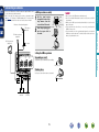
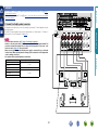
Connecting a TV
Cables used for connections
To listen to TV audio through this device, use the optical digital connection.
Component
video cable
Video cable (sold separately)
Video cable
NOTE
Y
PB
PB
PR
PR
Audio cable (sold separately)
Optical cable
TV
AUDIO
VIDEO
COMPONENT VIDEO
IN
Y
P B PR
VIDEO
IN
OPTICAL
OUT
Advanced version
The optical connection is not required when a TV compatible with the ARC function (Audio Return Channel
(HDMI 1.4a standard function)) is connected to this unit via an HDMI connection.
For details, see “About ARC (Audio Return Channel) function” (vpage 7) or refer to the instruction
manual for your TV.
Y
Basic version
•Select the connector to use and connect the device.
•For video connections, see “Converting input video signals for output (Video conversion function)”
(vpage 5).
•For instructions on HDMI connections, see “Connecting an HDMI-compatible device” (vpage 7).
Information
in Set as Necessary
Set this to change the digital input connector or component video input connector to which the input
source is assigned.
“Input Assign” (vpage 88)
10
Connecting a Blu-ray Disc player
Blu-ray Disc
player
Cables used for connections
VIDEO
COMPONENT VIDEO
OUT
Y
PB PR
Video cable (sold separately)
Video cable
Y
Y
PB
PB
PR
PR
Audio cable (sold separately)
Audio cable
L
L
R
R
AUDIO
OUT
L
R
L
R
L
R
Advanced version
Component
video cable
AUDIO
VIDEO
OUT
Basic version
•You can enjoy video and audio from a Blu-ray Disc.
•Select the connector to use and connect the device.
•For instructions on HDMI connections, see “Connecting an HDMI-compatible device” (vpage 7).
in Set as Necessary
When you want to play back HD Audio (Dolby TrueHD, DTS-HD, Dolby Digital Plus, DTS Express) and Multichannel PCM with this unit, use an HDMI connection (vpage 7 “Connecting an HDMI-compatible
device”).
11
Information
Set this to change the digital input connector or component video input connector to which the input
source is assigned.
“Input Assign” (vpage 88)
Connecting a DVD player
Connecting a set-top box (Satellite tuner/cable TV)
•You can watch satellite or cable TV.
•Select the connector to use and connect the device.
•For instructions on HDMI connections, see “Connecting an HDMI-compatible device” (vpage 7).
Cables used for connections
Cables used for connections
Video cable (sold separately)
Video cable (sold separately)
Video cable
Basic version
•You can enjoy video and audio from a DVD.
•Select the connector to use and connect the device.
•For instructions on HDMI connections, see “Connecting an HDMI-compatible device” (vpage 7).
Video cable
Y
Y
PB
PB
PR
PR
Audio cable (sold separately)
Audio cable
Audio cable (sold separately)
Audio cable
L
L
R
R
L
L
R
R
Coaxial
digital cable
Satellite tuner/
Cable TV
Coaxial
digital cable
VIDEO
VIDEO
OUT
AUDIO
AUDIO
OUT
L
R
Advanced version
Component
video cable
COAXIAL
OUT
DVD player
AUDIO
VIDEO
OUT
AUDIO
OUT
L
R
L
R
L
R
COAXIAL
OUT
L
R
L
R
in Set as Necessary
Set this to change the digital input connector or component video input connector to which the input
source is assigned.
“Input Assign” (vpage 88)
in Set as Necessary
Set this to change the digital input connector or component video input connector to which the input
source is assigned.
“Input Assign” (vpage 88)
12
Information
VIDEO
COMPONENT VIDEO
OUT
Y
PB PR
Connecting a video cassette recorder
Connecting a digital camcorder
•You can enjoy video and audio from a digital camcorder.
•For instructions on HDMI connections, see “Connecting an HDMI-compatible device” (vpage 7).
Cables used for connections
Video cable (sold separately)
Cables used for connections
Video cable
Video cable (sold separately)
Audio cable (sold separately)
Video cable
Audio cable
L
L
R
R
AUDIO
VIDEO
AUDIO
VIDEO
IN
AUDIO
IN
L
R
VIDEO
OUT
AUDIO
OUT
L
R
L
R
R
L
L
VIDEO
AUDIO
VIDEO
OUT
AUDIO
OUT
L
R
L
R
L
R
R
R
in Set as Necessary
Set this to change the digital input connector or component video input connector to which the input
source is assigned.
“Input Assign” (vpage 88)
in Set as Necessary
Set this to change the digital input connector or component video input connector to which the input
source is assigned.
“Input Assign” (vpage 88)
You can enjoy games by connecting a game machine via the AUX1 INPUT connector. In this case, select
the input source to “AUX1”.
NOTE
NOTE
To record video signals through this unit, use the same type of video cable for connection between this
unit and the player as used for connection between this unit and the recorder.
When a non-standard video signal from a game machine or some other source is input, the video conversion
function might not operate. In this case, use the monitor output of the same connector as the input.
13
Information
L
L
R
Digital camcorder
Video cassette recorder
VIDEO
L
R
Advanced version
Audio cable (sold separately)
Audio cable
Basic version
•You can record video onto a video cassette tape.
•Select the connector to use and connect the device.
•When recording analog audio, use the analog connection.
•For instructions on HDMI connections, see “Connecting an HDMI-compatible device” (vpage 7).
Connecting an iPod or USB memory device to the USB port
Supported iPod models
Cables used for connections
To connect an iPod to this unit, use the USB cable supplied with the iPod.
USB memory
device
•iPod / iPod classic
iPod
Basic version
You can enjoy music stored on an iPod or USB memory device.
or
Advanced version
•iPod nano
Information
marantz does not guarantee that all USB memory devices will operate or receive power. When using a
portable USB connection type HDD of the kind to which an AC adapter can be connected to supply power,
use the AC adapter.
NOTE
•iPod touch
•USB memory devices will not work via a USB hub.
•Do not use an extension cable when connecting a USB memory device. This may cause radio interference
with other devices.
•This unit does not support playback on an iPad. Do not connect an iPad to the unit.
•When connecting an iPhone to this unit, keep the iPhone at least 20 cm away from this unit. If the iPhone
is kept closer to this unit and a telephone call is received by the iPhone, noise may be output from this
device.
•iPhone
14
Connecting an antenna
Direction of broadcasting station
FM outdoor
antenna
the stand section
1 Put
through the bottom of the
loop antenna from the
rear and bend it forward.
Stand
Square
hole
Loop
antenna
Projecting
part
75 Ω coaxial
cable
q
w
e
nnUsing the AM loop antenna
Suspending on a wall
Nail, tack, etc.
Standing alone
Use the procedure shown above to assemble.
White
AM outdoor
antenna
Ground
15
Information
Suspend directly on a wall without assembling.
Black
•Do not connect two FM antennas simultaneously.
•Even if an external AM antenna is used, do not disconnect the AM
loop antenna.
•Make sure the AM loop antenna lead terminals do not touch metal
parts of the panel.
•If the signal has noise interference, connect the ground terminal
(GND) to reduce noise.
•If you are unable to receive a good broadcast signal, we recommend
installing an outdoor antenna. For details, inquire at the retail store
where you purchased the unit.
Advanced version
the projecting part
2 Insert
into the square hole in
NOTE
the stand.
FM indoor antenna
(supplied)
AM loop antenna
(supplied)
nnAM loop antenna assembly
Basic version
•Connect the FM antenna or AM loop antenna supplied with the unit
to enjoy listening to radio broadcasts.
•After connecting the antenna and receiving a broadcast signal
(vpage 34 “Listening to FM/AM broadcasts”), fix the antenna
with tape in a position where the noise level becomes minimal.
Connecting a CD player
Connecting a record player
You can enjoy playing records.
Cables used for connections
Cables used for connections
Audio cable (sold separately)
Audio cable (sold separately)
Audio cable
L
L
R
R
Audio cable
L
L
R
R
CD player
AUDIO
AUDIO
AUDIO
OUT
L
R
OPTICAL
OUT
L
AUDIO
OUT
R
GND
L
R
Information
L
Advanced version
Turntable
(MM cartridge)
Optical cable
Basic version
•You can enjoy CD sound.
•Select the connector to use and connect the device.
R
in Set as Necessary
•This unit is compatible with record players with an MM cartridge. When you connect to a record player
with an MC cartridge, use a commercially available MC head amp or a step-up transformer.
•When you increase the volume without connecting the record player, there may be “booming” noise
from the speakers.
Set this to change the digital input connector to which the input source is assigned.
“Input Assign” (vpage 88)
NOTE
The SIGNAL GND terminal of this unit is not a safety ground connection. Connect it to reduce noise when
noise is excessive. Note that depending on the record player, connecting the ground line may have the
reverse effect of increasing noise. In this case, it is not necessary to connect the ground line.
16
By connecting a wireless receiver RX101 (sold separately) to this unit, you can receive and playback audio
signals from other devices using the Bluetooth Communication Function.
•Use a Bluetooth device that is A2DP compatible (vpage 138 “A2DP”).
•You can also use wireless receiver RX101 as an external IR receiver.
•For instructions on the wireless receiver settings, refer to the RX101’s operating instructions.
•You can connect this unit to an external device fitted with multi-channel sound audio output jacks to enjoy
music and video.
•The video signal can be connected in the same way as a Blu-ray Disc player / DVD player (vpage 11
“Connecting a Blu-ray Disc player”).
Wireless receiver RX101
Basic version
Connect a device that has a multichannel output
terminal
Connecting a wireless receiver (RX101)
Cables used for connections
Audio cable (sold separately)
L
L
R
R
Audio cable
Blu-ray Disc player / DVD player /
External decoder
Advanced version
Audio cable
AUDIO
SUBWOOFER
FRONT
L
CENTER
R
SURROUND
L
R
SURROUND
BACK
L
R
L
R
L
R
L
R
L
R
L
R
L
R
Remote control unit
You can enjoy listening to music by connecting a wireless receiver via the M-XPort input connector. In this
case, set the input source to “M-XPort”.
in Set as Necessary
NOTE
To play analog signals input from 7.1CH IN connectors, set “Input Mode” (vpage 91) to “7.1CH
IN”.
To use wireless receiver RX101 as external IR receiver, set the remote sensor function of this unit to
disable (vpage 117 “Remote control settings”).
When a device is connected to the SBL/SBR terminal of 7.1CH IN connectors, set “Amp Assign”
(vpage 101) to “NORMAL”.
17
Information
Bluetooth device
(A2DP Compatibility)
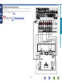
Connecting a external power amplifier
•When using just one surround back speaker, connect it to the left channel (L) terminal.
•Use the volume control on the subwoofer to control subwoofer volume.
•If the subwoofer volume sounds low, use the volume control provided on the subwoofer to adjust the
volume.
Cables used for connections
Audio cable (sold separately)
Audio cable
L
L
R
R
NOTE
Power amplifier
AUDIO
SUBSUBWOOFER WOOFER
1
2
AUDIO
FRONT CENTER SURROUND SURROUND
BACK
L
R
L
R
L
R
R
L
R
L
R
L
R
L
R
L
R
Information
L
Advanced version
•When external power amplifier have been connected to PRE OUT terminals, do not connect the speakers
to the speaker terminals.
•Depending on the settings in the “Amp Assign” (vpage 101) menu or listening mode, the channel
output from the SBL terminal or SBR terminal of the PRE OUT terminal differs.
Audio cable
Subwoofer
Basic version
•You can use this unit as a pre-amp by connecting a commercially available power amp to the PRE OUT
connector. Adding a power amp to each of the channels provides an even greater sound presence.
•Select the terminal to use and connect the device.
18
Connecting to a home network (LAN)
Cable (sold separately)
Ethernet
cable
Computer
nnBroadband internet connection
nnModem
Device that connects to the broadband circuit and conducts
communications on the Internet.
A type that is integrated with a router is also available.
nnRouter
When using this unit, we recommend you use a router equipped
with the following functions:
•Built-in DHCP server
This function automatically assigns IP addresses on the LAN.
•Built-in 100BASE-TX switch
When connecting multiple devices, we recommend a switching
hub with a speed of 100 Mbps or greater.
nnEthernet cable (CAT-5 or greater recommended)
Internet
To WAN side
To LAN port
LAN port/
Ethernet
connector
Router
•If you have an Internet provider contract for a line on which network
settings are made manually, make the settings at “Network Setup”
(vpage 107).
•With this unit, it is possible to use the DHCP and Auto IP functions
to make the network settings automatically.
•When using this unit with the broadband router’s DHCP function
enabled, this unit automatically performs the IP address setting and
other settings.
When using this unit connected to a network with no DHCP
function, make the settings for the IP address, etc., at “Network
Setup” (vpage 107).
•When setting manually, check the setting contents with the network
administrator.
For connections to the Internet, contact an ISP (Internet
Service Provider) or a computer shop.
19
•A contract with an ISP is required to connect to the Internet.
No additional contract is needed if you already have a broadband
connection to the Internet.
•The types of routers that can be used depend on the ISP. Contact an
ISP or a computer shop for details.
•marantz assumes no responsibility whatsoever for any
communication errors or troubles resulting from customer’s
network environment or connected devices.
•This unit is not compatible with PPPoE. A PPPoE-compatible router
is required if you have a contract for a type of line set by PPPoE.
•Do not connect an NETWORK connector directly to the LAN port/
Ethernet connector on your computer.
•To listen to audio streaming, use a router that supports audio
streaming.
Information
•Use only a shielded STP or ScTP LAN cable which is available at
retailer.
•Some flat type Ethernet cables are easily affected by noise.
We recommend using a normal type cable.
Modem
To LAN port
NOTE
Advanced version
Cables used for connections
Required system
Basic version
•This unit lets you play via your home network (LAN) music files
stored on a computer and music content such as that from Internet
radio.
You can also operate this unit from a computer using the Web
control function.
•You can update by downloading the latest firmware from the
marantz website.
For more information, on the menu, select “Firmware Update”
(vpage 114).
•See “Network Setup” on the menu (vpage 107) for more
information on network setting.
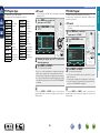
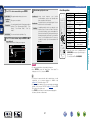
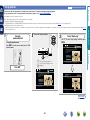
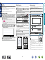
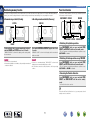
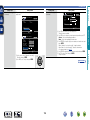
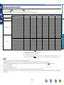
Here, we explain “Audyssey® Auto Setup”, which allows you to
automatically make the optimal settings for your speakers, and
“Network Setup”, which allows you to connect this unit to a home
network (LAN).
This unit lets you play via your home network (LAN) music files stored
on a computer and music content such as that from Internet radio.
Playback (Basic operation) (vpage 27)
Selecting a listening mode (SURROUND MODE)
(vpage 50)
The acoustic characteristics of the connected speakers and
listening room are measured and the optimum settings are made
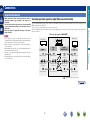
automatically. This is called “Audyssey® Auto Setup”.
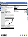
To perform measurement, place the setup microphone in
multiple locations all around the listening area. For best results,
we recommend you measure in six or more positions, as shown
in the illustration (up to eight positions).
•When performing Audyssey® Auto Setup, Audyssey MultEQ® XT/
Audyssey Dynamic EQ®/Audyssey Dynamic Volume® functions
become active (vpage 96).
•To set up the speakers manually, use “Speaker Setup”
(vpage 101) on the menu.
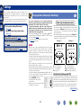
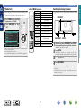
About setup microphone placement
•Measurements are performed by placing the setup microphone
successively at multiple positions throughout the entire listening
area, as shown in GExample qH. For best results, we recommend
you measure in six or more positions, as shown in the illustration
(up to eight positions).
•Even if the listening environment is small as shown in GExample wH,
measuring at multiple points throughout the listening environment
results in more effective correction.
NOTE
•Make the room as quiet as possible. Background noise can disrupt
the room measurements. Close windows, silence cell phones,
televisions, radios, air conditioners, fluorescent lights, home
appliances, light dimmers, or other devices as measurements may
be affected by these sounds.
•Cell phones should be placed away from all audio electronics during
the measurement process as Radio Frequency Interference (RFI)
may cause measurement disruptions (even if the cell phone is not
in use).
•Do not unplug the setup microphone from the main unit until
Audyssey® Auto Setup is completed.
•Do not stand between the speakers and setup microphone or allow
obstacles in the path while the measurements are being made. This
will cause inaccurate readings.
•Loud test sounds may be played during Audyssey® Auto Setup. This
is part of normal operation. If there is background noise in room,
these test signals will increase in volume.
•Operating VOLUME +, – during
the measurements will cancel the
measurements.
•Measurement cannot be performed when
headphones are connected.
GExample qH
GExample wH
FL SW C
FL SW C
FR
( : Measuring positions)
*M
SL
SBL
FL
FR
C
SW
Front speaker (L)
Front speaker (R)
Center speaker
Subwoofer
FR
( : Measuring positions)
SR
*M
SL
SBR
SBL
SL
SR
SBL
SBR
Information
Playback (Advanced operation) (vpage 68)
Set up speakers (Audyssey® Auto Setup)
SR
SBR
Surround speaker (L)
Surround speaker (R)
Surround back speaker (L)
Surround back speaker (R)
About the main listening position (*M)
The main listening position is the position where listeners would
normally sit or where one would normally sit alone within the listening
environment. Before starting Audyssey® Auto Setup, place the setup
microphone in the main listening position. Audyssey MultEQ® XT uses
the measurements from this position to calculate speaker distance,
level, polarity, and the optimum crossover value for the subwoofer.
vSee overleaf
20
Advanced version
nn Set up speakers (Audyssey® Auto Setup)
(vpage 20)
nn Making the network settings (Network Setup)
(vpage 26)
Basic version
Settings
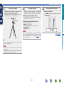
Set up speakers (Audyssey® Auto Setup)
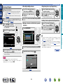
Set up the microphone
Mount the setup microphone on a tripod or stand
and place it in the main listening position.
When placing the setup microphone, adjust the height of the
sound receptor to the level of the listener’s ear.
Sound receptor
Set up the subwoofer
If using a subwoofer capable of the following
adjustments, set up the subwoofer as shown below.
nn When using a subwoofer with a direct mode
3
Set up the remote control unit
nn Set up the operation mode
Press AMP to set the remote control unit to AMPoperation mode.
Set the direct mode to “On” and disable the volume adjustment
and crossover frequency setting.
nn When using a subwoofer without a direct mode
Make the following settings:
•Volume : “12 o’clock position”
•Crossover frequency : “Maximum/Highest Frequency”
•Low pass filter : “Off”
•Standby mode : “Off”
NOTE
When you use two subwoofers, please adjust the subwoofer
volume controls individually so that each subwoofer level is as close
as possible to 75 dB using the test tone (vpage 103) before
Audyssey® Auto Setup.
Advanced version
Setup
microphone
2
Basic version
1
Press AMP
vSee overleaf
Information
If you do not have a tripod or stand, set up the microphone on, for
example, a seat without a back.
NOTE
•Do not hold the setup microphone in your hand during
measurements.
•Avoid placing the setup microphone close to a seat back or wall as
sound reflections may give inaccurate results.
21
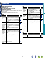
Set up speakers (Audyssey® Auto Setup)
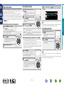
Detection & Measurement (Main)
Preparation
4
Basic version
STEP 2
STEP 1
Connect the setup microphone to the SETUP MIC
jack of this unit.
6 Select “Measure” and then press ENTER.
When measuring begins, a test tone is output from each
speaker.
When the setup microphone is
connected, the following screen is
displayed.
AUDYSSEY AUTO SETUP
7
The detected speakers are displayed.
•The illustration below shows an example of when the front
speakers, center speaker, subwoofer, and surround speakers have
been detected.
AUDYSSEY AUTO SETUP
Amp Assign
Channel Select
STEP2 Speaker
Front
Center
Subwoofer
Surround
Surround Back
Auto Setup Start
Start Auto Setup
Enter
RETURN
Cancel
Retry
Next
Detection Check
Yes
Yes
Yes
Yes
2spkrs
1 2 3 4 5 6
Measurement
Here, we explain setup using the example of 7.1-channel speaker
playback using surround back speakers.
For setup of surround speaker systems other than 7.1-channels,
follows steps 3 and 4 in “Set up “Amp Assign”” (vpage 64).
If unused channels are set with “Channel Select”, measuring time
can be shortened. For setting, perform steps 6 to 9 of “Set up
“Channel Select”” (vpage 65).
If a connected speaker is not displayed, the speaker may not be
connected correctly. Check the speaker connection.
i to select “Auto Setup
5 Use
Start” and then press ENTER.
Use i to select “Next → Measurement” and then
8 press
ENTER.
RETURN
Enter
Cancel
Proceed to next after checking speaker connection result
NOTE
22
When performing Audyssey® Auto Setup over
again
Press ui to select “Retry”, and then press ENTER.
When measuring has stopped
qPress RETURN, to the “Cancel auto setup?” prompt is displayed.
wPress o to select “Yes”, then press ENTER.
Setting up the speakers again
Repeat the operation from step 4 of STEP 1 Preparation
.
vSee overleaf
Information
STEP1 Preparation
1 2 3 4 5 6
Connect the speakers and place them according
to the recommendations in the manual.
Set the following items
If necessary.
•Measurement requires several minutes.
NOTE
If “Caution!” is displayed:
Go to “Error messages” (vpage 25),
check any related items, and perform the
necessary procedures.
If the problem is resolved, return and restart
“Audyssey® Auto Setup”.
Advanced version
•In STEP 2, you will perform measurements at the main listening
position.
•This step automatically checks the speaker configuration and speaker
size, and calculates the channel level, distance, and crossover
frequency.
It also corrects distortion in the listening area.
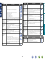
Set up speakers (Audyssey® Auto Setup)
Calculation
Measurement (2nd – 8th)
•In STEP 3, you will perform measurements at multiple positions (two
to eight positions) other than the main listening position.
•Just one position can be measured but measuring multiple positions
increases the accuracy of the correction of acoustic distortion within
the listening area.
The measurement of the second
position starts. Measurements can be
made in up to eight positions.
When measurement of position 8 is completed,
“Measurements finished.” message is displayed.
AUDYSSEY AUTO SETUP
a
On the
screen, use ui to select “Next →
11 Calculation”,
and then press ENTER.
STEP 3
Measuring results are analyzed, and the frequency response of
each speaker in the listening room is determined.
1 2 3 4 5 6
STEP3 Measurement (Finish)
Measurements finished.
AUDYSSEY AUTO SETUP
STEP4 Calculation
Now calculating...Please wait.
1 2 3 4 5 6
20%
Retry
Next
Calculation
Enter
Proceed to next (Calculation)
RETURN
Cancel
Advanced version
9
Move the setup microphone to
position 2, use ui to select
“Measure”, and then press
ENTER.
10 Repeat step 9, measuring positions 3 to 8.
Basic version
STEP 4
STEP 3
AUDYSSEY AUTO SETUP
STEP3 Measurement (2nd)
Please place the microphone at ear
height at 2nd Iistening position.
1 2 3 4 5 6
Measure
Next
vSee overleaf
Calculation
RETURN
Enter
Cancel
Start measurement. Output large test tone during measuring
If you want to omit measurements from the next position onward,
select “Next
Calculation”.
(Go to STEP4 Calculation )
23
Information
•Analysis takes several minutes to complete. The time required for
this analysis depends on the number of speakers connected.
The more connected speakers there are, the longer it takes to
perform analysis.
Set up speakers (Audyssey® Auto Setup)
STEP 6
Check
Finish
Store
ui to select the item you
12 Use
want to check, and then press
ENTER.
14 Select “Store” and then press ENTER.
Save the measurement results.
AUDYSSEY AUTO SETUP
1 2 3 4 5 6
AUDYSSEY AUTO SETUP
Finish
Storing complete.
Auto Setup is now finished.
Please unplug microphone.
AUDYSSEY AUTO SETUP
Store
1 2 3 4 5 6
STEP5 Check
Check processing results.
To proceed, press “Next”.
Enter
Apply and store measurement result
Speaker Config. Check
Distance Check
Channel Level Check
Crossover Freq. Check
Next
Turn on Dynamic Volume?
Cancel
Yes
No
Exit
Turn Dynamic Volume off and exit Auto Setup
Store
Proceed to next (Store)
Enter
RETURN
Cancel
1 2 3 4 5 6
STEP6 Store
Now storing...Please wait.
20%
nn When turning Dynamic Volume® on
Use i to select “Next → Store” and then press
ENTER.
NOTE
•If the result differs from the actual connection status, or if “Caution!”
is displayed, see “Error messages” (vpage 25). Then carry out
Audyssey® Auto Setup again.
•If you change speaker positions or orientation, perform Audyssey®
Auto Setup again to find the optimal equalizer settings.
•This feature adjusts the output volume to the optimal level while
constantly monitoring the level of the audio input to the unit.
Optimal volume control is performed automatically without any
loss in the dynamism and clarity of the sound when, for example,
the volume suddenly increases for commercials shown during
television programs.
•Use u to select “Yes”, and then press ENTER.
The unit automatically enters “Medium” mode.
•Saving the results requires about 10 seconds.
•If the measuring results are not to be saved, press RETURN. A
message “Cancel auto setup?” will be displayed. Press o then
select “Yes”. All the measured Audyssey® Auto Setup data will
be erased.
•During saving of measurements results, “Now storing...Please
wait.” is displayed. When saving is completed, “Storing complete.
Auto Setup is now finished.” is displayed.
NOTE
During saving of measurement results, be sure not to turn off the
power.
24
nn When turning Dynamic Volume® off
•Use i to select “No”, and then press ENTER.
NOTE
After performing Audyssey® Auto Setup, do not change the speaker
connections or subwoofer volume. In event of a change, perform
Audyssey® Auto Setup again.
Information
AUDYSSEY AUTO SETUP
•Subwoofers may measure a greater reported distance than
the actual distance due to added electrical delay common in
subwoofers.
•If you want to check another item, press RETURN.
13
RETURN
1 2 3 4 5 6
Advanced version
STEP6 Store
Press “Store” to store calculation results.
the setup microphone from the unit’s SETUP
15 Unplug
MIC jack.
®
16 Set Audyssey Dynamic Volume .
Basic version
STEP 5
Set up speakers (Audyssey® Auto Setup)
NOTE
•An error message is displayed if Audyssey® Auto Setup could not be completed due to speaker placement, the measurement environment, etc. If this happens, check the relevant items, be sure to take the necessary
measures, then perform Audyssey® Auto Setup over again.
•If the result still differs from the actual connection status after remeasurement or the error message still appears, it is possible that the speakers are not connected properly. Turn this unit off, check the speaker
connections and repeat the measurement process from the beginning.
•Be sure to turn off the power before checking speaker connections.
AUDYSSEY AUTO SETUP
Caution!
No microphone or speaker
Measures
•The connected setup microphone is broken, or a device other than the
supplied setup microphone is connected.
•Not all speakers could be detected.
•The front L speaker was not properly detected.
•Connect the included setup microphone to the SETUP MIC jack of this unit.
•There is too much noise in the room for accurate measurements to be
made.
•Speaker or subwoofer sound is too low for accurate measurements to be
made.
•Either turn off any device generating noise or move it away.
•Perform again when the surroundings are quieter.
•Check the speaker installation and the direction in which the speakers are
facing.
•Adjust the subwoofer’s volume.
•The displayed speaker could not be detected.
(The screen on the left indicates that the front right speaker cannot be
detected.)
•Check the connections of the displayed speaker.
•The displayed speaker is connected with the polarity reversed.
(The screen on the left indicates that the polarity phases of the front right
speakers are reversed.)
•Check the polarity of the displayed speaker.
•For some speakers, this error message may be
displayed even if the speaker is properly connected.
If you are sure the connection is correct, press ui
to select “Skip”, then press ENTER.
•Check the speaker connections.
Retry
RETURN
Cancel
AUDYSSEY AUTO SETUP
Caution!
Ambient noise is too high
or level is too low
Retry
RETURN
Cancel
AUDYSSEY AUTO SETUP
1 2 3 4 5 6
Caution!
Front R
None
Retry
RETURN
Cancel
AUDYSSEY AUTO SETUP
1 2 3 4 5 6
Caution!
Front R
Phase
Retry
Skip
RETURN
Cancel
25
Information
Error details
Advanced version
Examples
Basic version
Error messages
Set up speakers (Audyssey® Auto Setup)
This function enables you to check the measurement results and equalizer characteristics after Audyssey®
Auto Setup.
This unit can be connected to a home network (LAN) to listen to Internet radio or play back music files and
still image (JPEG) files stored on a computer.
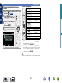
1 Use ui to select “Parameter Check” and then press ENTER.
SPEAKER SETUP
Auto Setup
Amp Assign
Speaker Config.
Bass Setting
Distance
Channel Level
This unit performs automatic network setup due to the DHCP function.
When connecting to a network that has no DHCP function, perform the setting in “Network
Connecting” (vpage 107).
Audyssey Auto Setup
Parameter Check
Check auto setup measurement results
2 Use ui to select the item you want to check, then press ENTER or p.
Advanced version
1 Connect the Ethernet cable (vpage 19 “Connecting to a home network (LAN)”).
2 Turn on this unit (C page 5 “Getting Started”).
Basic version
Making the network settings
(Network Setup)
Parameter Check
Measurement results for each speaker are displayed.
Speaker Config. Check
Check the distance.
Channel Level Check
Check the channel level.
Crossover Freq. Check
Check the crossover frequency.
EQ Check
Information
Distance Check
Check the speaker configuration.
Check the equalizer.
•If “EQ Check” is selected, press ui to select equalizing curve (“Audyssey” or “Audyssey Flat”) to
be checked.
Use ui to switch the display between the different speakers.
3 Press RETURN.
The confirmation screen reappears. Repeat step 2.
Retrieving Audyssey® Auto Setup settings
If you set “Restore” to “Yes”, you can return to Audyssey® Auto Setup measurement result (value
calculated at the start by MultEQ® XT) even when you have changed each setting manually.
26
Important information
Settings (vpage 20)
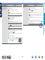
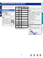
nn Selecting the input source (vpage 27)
nn Adjusting the master volume (vpage 28)
nn Turning off the sound temporarily (vpage 28)
Playback (Advanced operation) (vpage 68)
Selecting the input source
Press the input source select button
(BD, DVD, SAT, TV, NET/USB, CD,
TUNER or M-XP) twice to be played
back.
When an input source select button (BD,
DVD, SAT, TV, CD, NET/USB, TUNER or
M-XP) is pressed once, the unit switches
to device selected by the operating mode of
the remote control. If the input source select
button is then pressed again twice, the input
source for the unit is switched.
•When 21 is pressed, the input source of this unit is switched
to “NET/USB” and the connected iPod is automatically played
(vpage 31 “iPod play function”).
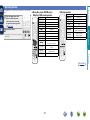
nnUsing the SOURCE d f button on the remote
control unit
Press SOURCE d or SOURCE f.
•Every time you press SOURCE d or
SOURCE f, the input source switches in
the following order.
BD
DVD
M-XPort
VCR
TUNER
SAT
PHONO
GAME
CD
AUX1
TV
AUX2
NET/USB
nnUsing the knob on the main unit
Turn INPUT SELECTOR.
•Every time you turn INPUT SELECTOR, the input source switches
in the following order.
BD
DVD
M-XPort
VCR
TUNER
SAT
PHONO
GAME
CD
AUX1
TV
AUX2
NET/USB
vSee overleaf
•Select input source “AUX1” to play back music from an audio
system connected to the AUX1 INPUT connector.
•The input source “GAME” is selected to playback from a game
device connected to GAME connector of HDMI IN.
•Select the input source “VCR”, “GAME”, “AUX1”, “AUX2” or
“PHONO” using one of the following methods.
•SOURCE df button on the remote control unit
(“Using the SOURCE df button on the remote control unit”
provided on the right)
•INPUT SELECTOR knob on the main unit
(“Using the knob on the main unit” provided on the right)
•“SOURCE SELECT” menu
(“Using the “SOURCE SELECT” menu”(vpage 28)
BD
27
Information
Selecting a listening mode (SURROUND MODE)
(vpage 50)
NOTE
Also refer to the operating instructions of the connected devices
when playing them.
You can also use the following operation to select an input
source.
Advanced version
nn Playing a Blu-ray Disc player/DVD player
(vpage 29)
nn Playing a CD player (vpage 29)
nn Playing an iPod (vpage 30)
nn Playing a USB memory device (vpage 32)
nn Tuning in radio stations (vpage 34)
nn Playing a network audio (vpage 38)
Before starting playback, make the connections between the different
devices and the settings on the unit.
Basic version
Playback (Basic operation)
Important information
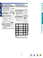
SOURCE SELECT
q
Source
w
Recent
The currently selected input
source is highlighted.
BD
Set the front speakers to be used
Use VOLUME +, – to adjust the
volume.
Press SPEAKER A/B.
nn When the “Volume Display” setting
(vpage 112) is “Relative”
Player
GAdjustable rangeH
–––
–80.5dB – 18.0dB
Video
nn When the “Volume Display” setting (vpage 112) is
“Absolute”
Network
Tuner
q Input Source
The name of the highlighted input source is displayed.
w Recently used sources
The recently used input sources (up to five) are displayed.
e Icons for the input sources in the different categories are
displayed.
qPress 3.
Display the “SOURCE SELECT” menu.
The input source is set and the source
selection menu is turned off.
•When using with an iPod connected directly to the USB port of this
unit, select “
(USB/iPod)” for the input source.
•Input sources that are not going to be used can be set ahead of time.
Make this setting at “Source Delete” (vpage 112).
•To turn off the source selection menu without selecting an input
source, press 3 again.
•When 3 is pressed, the AMP-operation mode starts automatically
(vpage 118).
BD
Front A
Front B
Front A+B
You can also operate via the main unit. In this case, perform the
following operations.
Turn VOLUME to adjust the volume.
Turning off the sound temporarily
Press MUTE.
•“MUTE” appears on the display.
appears on a TV screen.
•
•The sound is reduced to the level set at “Mute Level” (vpage 112).
•To cancel, press MUTE again. Muting can also be canceled by
adjusting the master volume.
28
Information
wUse uio p to select the input source,
then press ENTER.
GAdjustable rangeH 0.0 – 99.0
•The variable range differs according to the input signal and channel
level setting.
•Each time you press SPEAKER A/B,
the front speaker setting will change as
follows.
Advanced version
e
Adjusting the master volume
Basic version
nnUsing the “SOURCE SELECT” menu
The following describes the procedure for playing Blu-ray Disc player/
DVD player.
1
Prepare for playback.
Playing a CD player
The following describes the procedure for playing CD player.
1 Prepare for playback.
qTurn on the power of the subwoofer
and player.
wLoad the disc in the player.
qTurn on the power of the TV,
subwoofer and player.
wChange the TV input to the input of
this unit.
Press ON to turn on power to the
2 unit.
BD or DVD twice to switch an input source for
3 Press
a player used for playback.
4 Play the device connected to this unit.
Advanced version
eLoad the disc in the player.
ON to turn on power to the
2 Press
unit.
CD twice to switch the input
3 Press
source to the CD player.
4 Play the device connected to this unit.
Basic version
Playing a Blu-ray Disc player/DVD
player
Make the necessary settings on the player (language setting,
subtitles setting, etc.) beforehand.
Information
BD
29
Playing an iPod
1
Connect the iPod to the USB port (vpage 14
“Connecting an iPod or USB memory device to the
USB port”).
[1/7]
Favorites
Flickr
Last.fm
Napster
Display mode
Preset
Direct mode
P
P
Playable Music file
files
Video file
Active
buttons
[1/8]
Remote mode
z
Remote
control unit
(This unit)
P
iPod
Playlists
Artists
Albums
Songs
P
P
zzOnly the sound is played.
Podcasts
Genres
Composers
SEARCH
P/Search
NOTE
If the “iPod” is not displayed, the iPod may not be properly
connected. Reconnect it.
BD
ui to select the item, then press ENTER or p
6 toUseselect
the file to be played.
7 Press ENTER, p or 1.
Playback starts.
30
•You can specify the duration of the on-screen display to be displayed
(default: 30 sec) at menu “iPod” (vpage 113). Press uio p
to return to the original screen.
•To play back compressed audio with extended bass or treble
reproduction, we recommend playback in M-DAX mode
(vpage 99). The default setting is “OFF”.
•In Remote mode, press STATUS on the main unit during playback to
check the title name, artist name, and album name.
NOTE
•Depending on the type of iPod and the software version, some
functions may not operate.
•Note that marantz will accept no responsibility whatsoever for any
problems arising with the data on an iPod when using this unit in
conjunction with the iPod.
vSee overleaf
Information
ui to select “iPod”, then
4 Use
press ENTER or p.
iPod
Remote mode
Display iPod information on the TV screen.
•The unit display shows single-byte
alphanumeric characters and some
symbols only. “.” is displayed in place
of incompatible characters.
•In ”Remote mode”, the iPod display is
OK to disconnect.
as shown at right.
Direct mode
Display iPod information on the iPod screen.
•“Direct iPod” is displayed on the display of this unit.
•The Direct mode is not supported on fifth generation iPod or
first generation iPod nano.
Internet Radio
Media Server
iPod
CH+/-
•There are two modes for displaying the contents recorded on the
iPod.
Advanced version
2 Press ON to turn on power to the unit.
NET/USB twice to switch the input source to
3 Press
“NET/USB”.
SEARCH/INFO and hold it down for 2 seconds
5 Press
or more to select the display mode.
Basic version
You can play back both video, photo and audio.
Playing an iPod
Page searchz1 / Character sortz2
uio p
Cursor operation /
Auto search (cue, ui) /
Manual search (Press and hold, ui)
TV Z / X
TV INPUT
Remote / Direct mode switching
If 21 is pressed when an iPod (USB) is connected, the iPod starts
playback.
Press 21.
•This unit’s input source switches to
“NET/USB”.
•iPod playback starts.
Enter / Pause
Stop
Return
Pause
Playback / Pause
Stop
Auto search (cue)
Manual search
(fast-reverse/fast-forward)
Repeat playback
Random playback
TV power on/standby
(Default : marantz)
Switch TV input (Default : marantz)
Information
ENTER
(Press and release)
ENTER
(Press and hold)
RETURN
3
1
2
8 9
6 7
(Press and hold)
REPEAT 0
RANDOM 1
Function
Amp menu
Advanced version
Operation buttons
AMP MENU
SEARCH/INFO
(Press and release)
SEARCH/INFO
(Press and hold)
•Repeat playback (vpage 92 “Repeat”)
•Random playback (vpage 92 “Random”)
z1 When the menu screen is displayed, press SEARCH/INFO, then
press o (previous page) or p (next page).
To cancel, press ui or SEARCH/INFO twice.
z2 When the menu screen is displayed, press SEARCH/INFO twice,
then press o p to select the first letter you want to search mode.
•If it is not possible to search the list, “unsorted list...” is
displayed.
To cancel, press ui or SEARCH/INFO.
If
the list is not in alphabetical order, you may not be able to perform
a character sort.
BD
Basic version
iPod play function
nniPod operation
31
Playing a USB memory device
GCompatible formatsH
USB memory devices z1
Important information
nnUSB memory devices
WMA (Windows Media Audio)
Pz2
MP3 (MPEG-1 Audio Layer-3)
P
WAV
P
MPEG-4 AAC
Pz3
FLAC (Free Lossless Audio Codec)
P
JPEG
P
z1USB
•This unit is compatible with MP3 ID3-Tag (Ver. 2) standard.
•This unit can show the artwork that was embedded by using MP3 ID3-Tag Ver. 2.3 or 2.4.
•This unit is compatible with WMA META tags.
•WAV format Quantization bit rate: 16 bits
•FLAC format Quantization bit rate: 16 or 24 bits
z2 Copyright-protected files can be played on certain portable players compatible with MTP.
z3 Only files that are not protected by copyright can be played on this unit.
Content downloaded from pay sites on the Internet are copyright protected. Also, files encoded in
WMA format when ripped from a CD, etc. on a computer may be copyright protected, depending on
the computer’s settings.
Album art function
When an MP3 music file includes album art data, the album art can be displayed while playing the file.
Slide show function
Still picture (JPEG) files stored on USB memory devices can be played as slide shows.
The duration each picture is displayed can be set (vpage 92).
GCompatible formatsH
nn Function that simultaneously plays back music and image files from the network
You can playback music and image files at the same time by playing back music files, and then playing
back image files.
Also, when selecting music files after playing back image files, press SEARCH/INFO when the music
playback screen is displayed. Music files and image files can be played back simultaneously. At this
time, set “Slide Show”(vpage 92) in the menu to “ON”.
Internet Radio
Extension
48 – 192 kbps
.wma
MP3 (MPEG-1 Audio Layer-3)
32/44.1/48 kHz
32 – 320 kbps
.mp3
WAV
32/44.1/48 kHz
–
.wav
MPEG-4 AAC
32/44.1/48 kHz
16 – 320 kbps
.aac/
.m4a/
.mp4
32/44.1/48/88.2/96 kHz
–
.flac
vSee overleaf
Title
Radio station MP3 32kbps
Preset
Bit rate
32/44.1/48 kHz
FLAC (Free Lossless Audio Codec)
Now Playing
CH+/-
Sampling frequency
WMA (Windows Media Audio)
MEMORY
Memory
Select
SEARCH
Picture View
Network contents that can be played back simultaneously are as follows.
•Music files: Favorites,
Internet Radio, Media server, USB, iPod Remote Mode (NET/USB)
•Image files: Media server, USB, Flickr
BD
32
Information
This unit plays back image (JPEG) files in the orientation in which they are stored in the folder.
Advanced version
A USB memory device can be connected to the USB port of this unit to play music and still picture
(JPEG) files stored on the USB memory device.
Also, files stored on an iPod can be played when the iPod is connected directly to the USB port of this
unit. See “Playing an iPod” (vpage 30).
•Only USB memory devices conforming to mass storage class and MTP (Media Transfer Protocol)
standards can be played on this unit.
•This unit is compatible with USB memory devices in “FAT16” or “FAT32” format.
04:01
100%
Basic version
Playing back music or still picture (JPEG) files recorded on a USB memory device.
Playing a USB memory device
the USB memory device to the USB port
1 Connect
(vpage 14 “Connecting an iPod or USB memory
device to the USB port”).
[1/7]
NOTE
Favorites
Internet Radio
Media Server
USB
Flickr
Last.fm
Napster
CH+/-
•You can specify the duration of the on-screen display to be displayed
(default: 30 sec) at menu “NET/USB” (vpage 113). Press uio
p to return to the original screen.
•To play back compressed audio with extended bass or treble
reproduction, we recommend playback in M-DAX mode
(vpage 99). The default setting is “OFF”.
•If the USB memory device is divided into multiple partitions, only the
top partition can be selected.
•This unit is compatible with MP3 files conforming to “MPEG-1 Audio
Layer-3” standards.
Preset
[1/9]
USB
nnOne touch play function
You can play back music files and image files stored on a USB
memory device at the same time simply by pressing ONE TOUCH
PLAY on the main unit.
D&M1
D&M2
D&M3
Music1.mp4
Music2.mp3
Press ONE TOUCH PLAY.
Music3.m4a
Music4.m4a
SEARCH
P/Search
•Selecting
in the “SOURCE SELECT” menu, lets you directly
select “USB/iPod”.
4
ui to select the file, then press ENTER, p or
5 Press
1.
Press ui to select the search item or folder, then
press ENTER or p.
Playback starts.
“ONE TOUCH PLAY” is shown on the display, and the music and
image files on the USB memory device are played in list order.
If there are no music files on the USB memory device, only images
are played. However, if there are no image files on the USB memory
device, only musics are played.
NOTE
Place music and image files that you want to play back directly onto
the USB memory device. Files inside folders cannot be played.
uio p
ENTER
(Press and release)
ENTER
(Press and hold)
RETURN
3
1
2
8 9
1–8
REPEAT 0
RANDOM 1
Function
Last played internet radio station
Preset channel (1 – 3) selection
Amp menu
Preset channel block selection
Page searchz1 / Character sortz2
Cursor operation /
Auto search (cue, ui)
Enter / Pause
Stop
Return
Pause
Playback / Pause
Stop
Auto search (cue)
Preset channel selection
Repeat playback
Random playback
TV power on/standby
TV Z / X
(Default : marantz)
TV INPUT
Switch TV input (Default : marantz)
PRESET +, –
Preset channel (A1 – G8) selection
•Repeat playback (vpage 92 “Repeat”)
•Random playback (vpage 92 “Random”)
•Slide show playback (vpage 92 “Slide Show”)
z1 When the menu screen is displayed, press SEARCH/INFO, then
press o (previous page) or p (next page).
To cancel, press ui or SEARCH/INFO twice.
z2 When the menu screen is displayed, press SEARCH/INFO twice,
then press o p to select the first letter you want to search mode.
•If it is not possible to search the list, “unsorted list...” is
displayed.
To cancel, press ui or SEARCH/INFO.
If the list is not in alphabetical order, you may not be able to perform
a character sort.
BD
33
Information
Use ui to select “USB”, then
3 press
ENTER or p.
•Note that marantz will accept no responsibility whatsoever for any
problems arising with the data on a USB memory device when using
this unit in conjunction with the USB memory device.
•USB memory devices will not work via a USB hub.
•marantz does not guarantee that all USB memory devices will
operate or be supplied power. When using a USB portable hard disk
that can draw power from an AC adapter, we recommend using the
AC adapter.
•It is not possible to connect and use a computer via the USB port of
this unit using a USB cable.
Operation buttons
V
P1 – P3
AMP MENU
SHIFT/TOP MENU
SEARCH/INFO
Advanced version
NET/USB to switch the
2 Press
input source to “NET/USB”.
nnUSB operation
Basic version
Playing files stored on USB memory
devices
Tuning in radio stations
1
Press BAND to select “FM” or
2 “AM”.
Press TUNER to switch the input
source to “TUNER”.
When listening to an FM broadcast.
AM
When listening to an AM broadcast.
Your favorite broadcast stations can be preset so that you can tune
them in easily. Up to 56 stations can be preset.
•Stations can be preset automatically at “Auto Preset”
(vpage 92). If “Auto Preset” is performed after performing
“Manual preset”, the “Manual preset” settings will be overwritten.
1 Tune in the broadcast station you want to preset.
TUNER
TUNER
AUTO
AUTO
Now Playing
FM
CH A
Now Playing
FM
CH A
87.50MHz
TUNING
TUNING
PRESET
Preset
BAND
MEMORY
Band
Memory
T.MODE
SEARCH
Mode
Search
Tune in the desired broadcast station.
PRESET
Tuning
Preset
BAND
MEMORY
Band
Mode
T.MODE
Memory
Search
SEARCH
2 Press MEMORY.
TUNER
qTo tune in automatically (Auto tuning)
Press T.MODE to light the “AUTO” indicator on the display, then
use TUNING + or TUNING – to select the station you want to
hear.
wTo tune in manually (Manual tuning)
Press T.MODE to turn off the display’s “AUTO” indicator, then
use TUNING + or TUNING – to select the station you want to
hear.
AUTO
SHIFT
TUNING
PRESET
•If the desired station cannot be tuned in with auto tuning, tune it in
manually.
•When tuning in stations manually, press and hold TUNING + or
TUNING – to change frequencies continuously.
•The time (default : 30 sec) for which the menu are displayed can be
set at menu “Tuner” (vpage 113). Press uio p to return to
the original screen.
BD
Now Playing
To store preset:
CH A
Tuning
Preset
ST.Name HD1
Select A1-G8
FM 97.90MHz
CH+/Song
Title MEMORY
BAND
MEMORY
Band
Memory
A1
T.MODE
SEARCH
Mode
Search
Press SHIFT/TOP MENU to select the block (A to G) in
3 which
the channel (1 to 8 per a block) is to be preset,
then press PRESET +, PRESET – or 1 – 8 to select the
preset number.
4 Press MEMORY again to complete the setting.
•To preset other stations, repeat steps 1 to 4.
34
Block (A – G)
and
Channel (1 – 8)
A1 – A8
B1 – B8
C1 – C8
D1 – D8
E1 – E8
F1 – F8
G1 – G8
Default Settings
87.50 / 89.10 / 98.10 / 108.00 / 90.10 / 90.10 /
90.10 / 90.10 MHz
522 / 603 / 999 / 1404 / 1611 kHz,
90.10 / 90.10 / 90.10 MHz
90.10 MHz
90.10 MHz
90.10 MHz
90.10 MHz
90.10 MHz
Specify a name for the preset broadcast station
(Preset Name) (vpage 93)
vSee overleaf
Information
3
Tuning
87.50MHz
Default settings
Advanced version
FM
nnPresetting radio stations (Manual preset)
Basic version
Listening to FM/AM broadcasts
Tuning in radio stations
1
Press SHIFT/TOP MENU to select
the memory block (A to G).
TUNER
Preset Channel
A8
A7
CH A
A6
A5
A3
A2
TUNING
PRESET
A1
Tuning
Preset
FM
90.10MHz
STEREO
You can enter the receiving frequency directly to tune in.
1 Press SEARCH/INFO.
TUNER
AUTO
AUTO
90.10MHz
Now Playing
FM 90.10MHz
ST.Name
HD1
FM
FM 97.90MHz
90.10MHz
Song Title
FM ---.--MHz
DIRECT TUNE
CH A1
FM 108.00MHz
FM
Use this function to automatically tune to FM stations that provide
the RDS service.
Press TUNER twice to switch the
1 input
source to “TUNER”.
Press SEARCH/INFO to select
2 “RDS”.
TUNER
Artist Name
FM 98.10MHz
Program Type
FM
nnRDS search
RDS
89.10MHz
87.50MHz
BAND
Band
MEMORY
Memory
T.MODE
SEARCH
Mode
Search
PRESET +, PRESET – or
2 Press
1 – 8 to select the desired preset
channel.
TUNING
PRESET
2
Tuning
Preset
BAND
MEMORY
Band
Memory
0-9
SEARCH
Input
Search
Input frequencies using the 0 – 9.
RDS station
PTY
Program category
FM 97.90MHz
Traffic
info
RT
Radio
Artisttext
Name
Song Title
Program Type
A1 FM 87.50MHz
Search mode
BAND
Tuning
Band
The preset frequency is tuned in.
RDS (Radio Data System)
Note that the RDS function only works when receiving RDS compatible
stations.
RDS (works only on the FM band) is a broadcasting service which
allows a station to send additional information along with the regular
radio program signal.
NOTE
The operations described as follows using
SEARCH/INFO will not function in areas in
which there are no RDS broadcasts.
35
Preset
MEMORY
CH+/-
Memory
Tuning
T.MODE Mode
SEARCH
Search
3 Press PRESET + or PRESET –.
The search for RDS stations begins automatically.
•If no RDS stations are found with the above operation, all the
reception bands are searched.
•When a broadcast station is found, that station’s name appears on
the display.
•If no RDS station is found when all the frequencies have been
searched, “NO RDS” is displayed.
If you press PRESET + or PRESET – within 5 seconds after the
broadcast station name is shown on the display, you can search for a
different station.
Information
3 When setting is completed, press ENTER.
PRESET
Now Playing
ST.Name HD1
TP
TUNING SEARCH
•If o is pressed, the immediately preceding input is cancelled.
BD
CH A
AUTO
RDS
Advanced version
A4
FM
nnDirect frequency tuning
Basic version
nnListening to preset stations
Tuning in radio stations
nnPTY search
PTY identifies the type of RDS program.
The program types and their displays are as follows:
News
Current Affairs
Information
Sports
Education
Drama
Culture
Science
Varied
Pop Music
Rock Music
EASY M
Easy Listening
Music
Light Classical
Serious Classical
Other Music
Weather
Finance
CHILDREN
Children’s
program
SOCIAL
RELIGION
PHONE IN
TRAVEL
LEISURE
JAZZ
COUNTRY
NATION M
OLDIES
FOLK M
DOCUMENT
Social Affairs
Religion
Phone In
Travel
Leisure
Jazz Music
Country Music
National Music
Oldies Music
Folk Music
Documentary
Press TUNER twice to switch the
1 input
source to “TUNER”.
Press SEARCH/INFO to select
2 “PTY”.
TUNER
Program category
RDS
CH A
PTY
TP
RT
NEWS
Artist Name DRAMA
Program Type
Search mode
BAND
Tuning
Band
TUNING SEARCH
Preset
AUTO
Now Playing
FM 97.90MHzSPORT
Song Title
EDUCATE
A1 FM 87.50MHz
PRESET
STEREO
AFFAIRS
ST.Name HD1 INFO
MEMORY
CH+/-
Memory
nnTP search
Use this function to find RDS stations broadcasting traffic programs
(TP stations).
Press TUNER twice to switch the
1 input
source to “TUNER”.
Press SEARCH/INFO to select
2 “TP”.
TUNER
RDS
Tuning
T.MODE Mode
SEARCH
Search
CH A
3
4 Press PRESET + or PRESET –.
Watching the display, press ui to call out the
desired program type.
PTY search begins automatically.
•If there is no station broadcasting the designated program type
with the above operation, all the reception bands are searched.
•The station name is displayed on the display after searching stops.
•If no station broadcasting the designated program type is found
when all the frequencies have been searched, “NO PROGRAMME”
is displayed.
If you press PRESET + or PRESET – within 5 seconds after the
broadcast station name is shown on the display, you can search for a
different station.
BD
TP identifies programs that carry traffic announcements.
This allows you to easily find out the latest traffic conditions in your
area before leaving home.
36
RDS station
PTY
Program category
TP
RT
TUNING
PRESET
STEREO
RDS
Now Playing
ST.Name HD1
FM 97.90MHz
Traffic
info
Song Title
Radio
Artisttext
Name
Program Type
A1 FM 87.50MHz
SEARCH
Search mode
BAND
Tuning
Band
Preset
AUTO
MEMORY
CH+/-
Memory
Tuning
T.MODE Mode
SEARCH
Search
3 Press PRESET + or PRESET –.
TP search begins automatically.
•If no TP station is found with the above operation, all the reception
bands are searched.
•The station name is displayed on the display after searching stops.
•If no other TP station is found when all the frequencies have been
searched, “NO PROGRAMME” is displayed.
If you press PRESET + or PRESET – within 5 seconds after the
broadcast station name is shown on the display, you can search for a
different station.
Information
LIGHT M
CLASSICS
OTHER M
WEATHER
FINANCE
TP (Traffic Program)
Advanced version
NEWS
AFFAIRS
INFO
SPORT
EDUCATE
DRAMA
CULTURE
SCIENCE
VARIED
POP M
ROCK M
Use this function to find RDS stations broadcasting a designated
program type (PTY).
Basic version
PTY (Program Type)
Tuning in radio stations
RT allows RDS stations to send text messages that appear on the
display.
“RT” appears on the display when radio text data is received.
to select
TUNER
RDS
CH A
RDS
RDS station
PTY
Program category
TP
RT
ST.Name HD1
FM 97.90MHz
Traffic
info
Song Title
Radio
Artisttext
Name
Program Type
STEREO
Now Playing
PRESET
Tuning
Preset
ON
Band
MEMORY
Memory
0–9
MEMORY
TV Z / X
A1 FM 87.50MHz
TUNING
AUTO
Mode
SEARCH
Search
TV INPUT
TUNING +, –
PRESET +, –
Function
Amp menu
Preset channel block selection
Direct frequency tuning / RDS Search
Cursor operation
Enter
Return
Switch search modes
FM/AM switching
Preset channel selection (1 – 8) /
Direct frequency tuning (0 – 9)
Preset memory registration
TV power on/standby
(Default : marantz)
Switch TV input (Default : marantz)
Tuning (up/down)
Preset channel selection / RDS Search
Switching the tuning increment
The tuning increment factory settings are 9 kHz for AM, and 0.05 MHz
for FM.
PURE DIRECT
ON/STANDBY
STATUS
While pressing down PURE DIRECT and STATUS,
1 insert
the main unit power plug into the wall socket.
“AM9/FM50” appears on the display.
2 Press STATUS.
“AM10/FM200” appears on the display, and the tuning
increment is switched to AM and FM are 10 kHz and 0.2 MHz.
3 Press PURE DIRECT.
4 Press ON/STANDBY.
•The tuner preset memory will be cleared if this operation is
performed.
•This setting will not revert to the default values even when the
microprocessor is reset.
37
Information
•While receiving an RDS broadcast station, the text data broadcast
from the station is displayed.
•To turn the display off, press o p.
•If no text data is being broadcast, “NO TEXT DATA” is displayed.
BD
Advanced version
1
Press SEARCH/INFO
2 “RT”.
Press TUNER twice to switch the
input source to “TUNER”.
Operation buttons
AMP MENU
SHIFT/TOP MENU
SEARCH/INFO
uio p
ENTER
RETURN
T.MODE
BAND
Basic version
nnTuner (FM/AM) operation
RT (Radio Text)
Playing a network audio
Slide show function
You can play back image (JPEG) files that are stored in folders on a media server and photographs on Flickr
as a slideshow. Also, you can set the time display that is shown during playback (vpage 92).
Important information
nnAbout the internet radio function
This unit plays back image (JPEG) files in the orientation in which they are stored in the folder.
•Internet radio refers to radio broadcasts distributed over the Internet.
Internet radio stations from around the world can be received.
•This unit is equipped with the following Internet radio functions:
•Stations can be selected by genre and location.
•Up to 56 Internet radio stations can be preset.
•Internet radio stations in MP3 and WMA (Windows Media Audio) format can be listened to.
•Your favorite radio stations can be registered by accessing an exclusive marantz Internet radio URL
from a Web browser on a computer.
•The function is managed for individual users, so you must provide your MAC or e-mail address.
Exclusive URL: http://www.radiomarantz.com
•The radio station database service may be suspended without notice.
•This unit’s Internet radio station list is created using a radio station database service (vTuner). This
database service provides a list edited and created for this unit.
nn Function that simultaneously plays back music and image files from the network
Internet Radio
Advanced version
You can playback music and image files at the same time by playing back music files, and then playing
back image files.
Also, when selecting music files after playing back image files, press SEARCH/INFO when the music
playback screen is displayed. Music files and image files can be played back simultaneously. At this
time, set “Slide Show”(vpage 92) in the menu to “ON”.
Now Playing
04:01
100%
nnMedia player
Title
Radio station MP3 32kbps
CH+/-
Preset
MEMORY
Memory
Select
SEARCH
Picture View
Network contents that can be played back simultaneously are as follows.
•Music files: Favorites, Internet Radio, Media server, USB, iPod Remote Mode (NET/USB)
•Image files: Media server, USB, Flickr
Album art function
vSee overleaf
When a WMA (Windows Media Audio), MP3 or MPEG-4 AAC file includes album art data, the album art
can be displayed while the music files are playing.
If you use Ver.11 or later of Windows Media Player, the album art for WMA files can be displayed.
38
Information
This function lets you play music files and playlists (m3u, wpl) stored on a computer (media server)
connected to this unit via a network.
With this unit’s network audio playback function, connection to the server is possible using one of the
technologies below.
•Windows Media Player Network Sharing Service
•Windows Media DRM10
BD
Basic version
Follow this procedure to play Internet radio stations or music or still picture (JPEG) files stored on a
computer.
Playing a network audio
Internet radio
Media server z1
WMA (Windows Media Audio)
P
P
MP3 (MPEG-1 Audio Layer-3)
P
P
WAV
P
MPEG-4 AAC
Pz2
FLAC (Free Lossless Audio Codec)
P
JPEG
P
Flickr is an online photograph sharing service that started in 2004. You can use the this unit to view
photographs that have been made public by Flickr users. You do not need an account to use Flickr. To
view photographs that you recorded yourself, you need an account in order to upload these photographs
to the Flickr server. For details, see the Flickr homepage.
http://www.flickr.com/
nnAbout Last.fm
Bit rate
Extension
32/44.1/48 kHz
48 – 192 kbps
.wma
MP3 (MPEG-1 Audio Layer-3)
32/44.1/48 kHz
32 – 320 kbps
.mp3
WAV
32/44.1/48 kHz
–
.wav
MPEG-4 AAC
32/44.1/48 kHz
16 – 320 kbps
.aac/
.m4a/
.mp4
32/44.1/48/88.2/96 kHz
–
.flac
BD
nnAbout Napster
Napster is a monthly subscription music distribution service provided by Napster LLC. This service
allows users to download and play pieces of music they want to hear on this unit. Before you can use
Napster, you will need to visit the Napster website on your PC to create an account and register as a
member. For details, access the following site:
http://www.napster.com/choose/index_default.html
39
Information
Sampling frequency
WMA (Windows Media Audio)
Advanced version
Last.fm learns what you love... and it’s a great way to discover new music.
Your new marantz AV receiver is very clever. You can create a free Last.fm profile when you start using
your marantz AV receiver and magically keep track of all the songs you hear.
When you sign in at www.last.fm, you can see your top music charts, view thousands of reviews,
biographies and artwork, and get recommendations for local performances you won’t want to miss.
With an affordable subscription you can enjoy an endless choice of personalised ad-free radio stations.
Check out www.last.fm/subscribe today for more details.
Your subscription also gives you access to Last.fm radio on a great range of music products, including
your marantz AV Receiver. This feature is not available in all countries. Visit www.last.fm/hardware
to find out more.
A server or server software compatible with distribution in the corresponding formats is required to play
music files via a network.
z1 Media server
•This unit is compatible with MP3 ID3-Tag (Ver. 2) standard.
•This unit can show the artwork that was embedded by using MP3 ID3-Tag Ver. 2.3 or 2.4.
•This unit is compatible with WMA META tags.
•WAV format Quantization bit rate: 16 bits
•FLAC format Quantization bit rate: 16 or 24 bits
z2 Only files that are not protected by copyright can be played on this unit.
Content downloaded from pay sites on the Internet are copyright protected. Also, files encoded in
WMA format when ripped from a CD, etc. on a computer may be copyright protected, depending on
the computer’s settings.
GCompatible formatsH
FLAC (Free Lossless Audio Codec)
Basic version
nnAbout Flickr
GCompatible formatsH
Playing a network audio
1
Prepare for playback.
q Check the network environment, then turn on this unit’s
power (vpage 19 “Connecting to a home network
(LAN)”).
w If settings are required, make the “Network Connecting”
(vpage 107).
•Selecting
in the “SOURCE SELECT”
menu, lets you directly select “Internet
Radio”.
4
Press ui to select the item you
want to play, then press ENTER
or p.
Simply press V to switch the input source to “Internet Radio”
and play the last played radio station.
Press V.
The source switches to “Internet Radio” and
the last played radio station plays.
•If INTERNET RADIO on the main unit is pressed, the same function
as with the remote control unit can be obtained.
•When V is pressed, the NET/USB-operation mode starts
automatically (vpage 118).
nnRecently played internet radio stations
Recently played internet radio stations can be selected from
“Recently Played”.
Up to 20 stations stored in “Recently Played”.
5
ui to select the station, then press ENTER or
6 Press
p.
The station list is displayed.
Information
Press ui to select “Recently
1 Played”,
then press ENTER or p.
ui to select the item you
2 Press
want to play, then press ENTER
Repeat step 4 until the station list is displayed.
or p.
Playback starts once buffering reaches “100%”.
vSee overleaf
BD
40
Advanced version
NET/USB twice to switch
2 Press
the input source to “NET/USB”.
Press ui to select “Internet
3 Radio”,
then press ENTER or p.
•There are many Internet radio stations on the Internet, and the
quality of the programs they broadcast as well as the bit rate of the
tracks varies widely.
Generally, the higher the bit rate, the higher the sound quality, but
depending on the communication lines and server traffic, the music
or audio signals being streamed may be interrupted. Inversely, lower
bit rates mean a lower sound quality but less tendency for the sound
to be interrupted.
•“Server Full” or “Connection Down” is displayed if the station is
busy or not broadcasting.
•On this unit, folder and file names can be displayed as titles. Any
characters that cannot be displayed are replaced with “.” (period).
•To play back compressed audio with extended bass or treble
reproduction, we recommend playback in M-DAX mode
(vpage 99). The default setting is “OFF”.
•You can specify the duration of the on-screen display to be displayed
(default: 30 sec) at menu “NET/USB” (vpage 113). Press uio
p to return to the original screen.
•When STATUS on the main unit is pressed, the display can be
switched between the title name and radio station name.
Basic version
nnPlaying the last played Internet radio station
Listening to internet radio
Playing a network audio
nnPresetting internet radio stations
Preset Internet radio stations can be selected directly.
ui to select “Search by Keyword”, then press 1
1 Press
ENTER or p.
Search by Keyword
ui to select
2 Press
then press ENTER.
Station
b
o
1
/
a/A
SHIFT
Select
a/A
c
P
2
:
d
q
3
˜
e
r
4
?
f
s
5
[
SPACE
g
t
6
\
h
u
7
]
i
v
8
ˆ
j
w
9
`
k
x
.
{
l m
y z
@ | }
INSERT DELETE
SEARCH
Input
CursorMode
RETURN
After pressing SHIFT/TOP MENU,
press PRESET +, PRESET – or 1 – 8 to
select the registered preset number.
This unit automatically connects to the
Internet and playback begins.
“Preset”,
Internet Radio
OK
Now Playing
Cancel
2 Input the characters, then press OK .
00:14
100%
CASTING
Registering Internet radio stations to preset
channel buttons
Preset
WMA 63kbps
CH+/-
•For character input, see page 85.
Favorites
Select
Preset
MEMORY
Memory
Internet Radio
Information
SHIFT/TOP MENU, then press PRESET +,
3 Press
PRESET – or 1 – 8 to select the desired preset number.
•Up to three Internet radio stations can be registered to the P1 – P3
buttons on the remote control unit or main unit.
•Recommended Internet radio stations have already been registered
to the P1 – P3 buttons.
While the internet radio station you
want to preset is playing, press and
hold P1 – P3 for at least 3 seconds.
The internet radio station is now preset.
To store preset:
00:14
100%
Select A1-G8
SHIFT
CH+/-
Now Playing
CASTING
MEMORY
NOTE
WMA 63kbps
CH+/-
4
BD
Preset
Select
MEMORY
Memory
Press MEMORY again to complete the setting.
The Internet radio station is now preset.
41
Advanced version
a
n
0
_
While the Internet radio station
you want to preset is playing,
press MEMORY.
nnListening to preset internet radio stations
Basic version
nnSearching stations by keyword
(Alphabetic strings)
If registered at a number that has already been preset, the previously
registered setting is cleared.
vSee overleaf
Playing a network audio
Press one of the registered P1 – P3.
nnRegistering internet radio stations as your
favorites
Favorites are listed at the top of the menu screen, so when a
station is registered as a favorite it can be tuned in easily.
nnListening to internet radio stations registered in
your favorites
3 to display the
1 Press
“SOURCE SELECT” menu,
Press ui to select the Internet
3 radio
station, then press ENTER
Internet Radio
or p.
Now Playing
This unit automatically connects to the
Internet and playback begins.
Favorites
00:14
100%
Preset
vSee overleaf
MP3 32kbps
CH+/-
Select
Preset
MEMORY
Memory
Information
3 Press o to select “Add”.
The Internet radio station is registered.
Internet Radio
Now Playing
00:14
100%
Is it registered?
Add
Cancel
MP3 32kbps
CH+/-
Preset
Select
MEMORY
Memory
•If you do not want to register the station, press p.
BD
Advanced version
MEMORY while the Internet radio station you
then select
(vpage 28).
1 Press
want to register is playing.
Press NET/USB to switch the
Press ui to select “Favorites”,
2
remote control operating mode
2 then press ENTER.
to “NET/USB”.
Basic version
Listening to an Internet radio station registered to a
preset channel button
42
Playing a network audio
3 to display the “SOURCE SELECT” menu,
1 Press
then select
(vpage 28).
NET/USB to switch the
2 Press
remote control operating mode
to “NET/USB”.
4 Press o to select “Remove”.
The selected Internet radio station is
cleared.
Favorites
TV Z / X
Preset
Cancel
MEMORY
Delete
•To cancel the operation without clearing the station, press p.
Function
Last played internet radio station
Preset channel (1 – 3) selection
Amp menu
Preset channel block selection
Page searchz1 / Character sortz2
Cursor operation
Enter
Stop
Return
Stop
Preset channel selection
Favorites / Preset memory
registration
TV power on/standby
(Default : marantz)
Switch TV input (Default : marantz)
Preset channel (A1 – G8) selection
z1 When the menu screen is displayed, press SEARCH/INFO, then
press o (previous page) or p (next page).
To cancel, press ui or SEARCH/INFO twice.
z2 When the menu screen is displayed, press SEARCH/INFO twice,
then press o p to select the first letter you want to search mode.
•If it is not possible to search the list, “unsorted list...” is
displayed.
To cancel, press ui or SEARCH/INFO.
If
the list is not in alphabetical order, you may not be able to perform
a character sort.
BD
43
Information
TV INPUT
PRESET +, –
Is it deleted?
Remove
CH+/-
MEMORY
[2/3]
Radio Algerienne Chaine 1
R
M
Operation buttons
V
P1 – P3
AMP MENU
SHIFT/TOP MENU
SEARCH/INFO
uio p
ENTER
(Press and release)
ENTER
(Press and hold)
RETURN
2
1–8
Advanced version
3
Press ui to select the Internet
radio station you want to clear,
then press MEMORY.
nnInternet radio operation
Basic version
nnClearing internet radio stations from your
favorites
Playing a network audio
Use this procedure to play music files, image files or playlists.
1 Prepare for playback.
3 to display the
2 Press
“SOURCE SELECT” menu,
then select
(vpage 28).
NET/USB to switch the
3 Press
remote control operating mode
to “NET/USB”.
then press ENTER or p.
Press ui to select the search item or folder, then
5 press
ENTER or p.
6 Repeat step 4 until the file is displayed.
7 Press ui to select the file, then press ENTER or p.
Playback starts once buffering reaches “100%”.
nnPlaying files that have been preset or registered
in your favorites
Files can be preset, registered in your favorites and played using
the same operations as for Internet radio stations (vpage 41,
42).
NOTE
•Presettings are erased by overwriting them.
•When the operations described below is performed, the media
server’s database is updated and it may no longer be possible to
play preset or favorite music files.
•When you quit the media server and then restart it.
•When music files are deleted or added on the media server.
Operation buttons
V
P1 – P3
AMP MENU
SHIFT/TOP MENU
SEARCH/INFO
uio p
ENTER
(Press and release)
ENTER
(Press and hold)
RETURN
3
1
2
8 9
1–8
REPEAT 0
RANDOM 1
Function
Last played internet radio station
Preset channel (1 – 3) selection
Amp menu
Preset channel block selection
Page searchz1 / Character sortz2
Cursor operation /
Auto search (cue, ui)
Enter / Pause
Stop
Return
Pause
Playback / Pause
Stop
Auto search (cue)
Preset channel selection
Repeat playback
Random playback
Favorites / Preset memory
MEMORY
registration
TV power on/standby
TV Z / X
(Default : marantz)
TV INPUT
Switch TV input (Default : marantz)
PRESET +, –
Preset channel (A1 – G8) selection
•Repeat playback (vpage 92 “Repeat”)
•Random playback (vpage 92 “Random”)
•Slide show playback (vpage 92 “Slide Show”)
z1 When the menu screen is displayed, press SEARCH/INFO, then
press o (previous page) or p (next page).
To cancel, press ui or SEARCH/INFO twice.
z2 When the menu screen is displayed, press SEARCH/INFO twice,
then press o p to select the first letter you want to search mode.
•If it is not possible to search the list, “unsorted list...” is
displayed.
To cancel, press ui or SEARCH/INFO.
If the list is not in alphabetical order, you may not be able to perform
a character sort.
BD
44
Information
ui to select the server
4 Press
including the file to be played,
•Connections to the required system and specific settings must be
made in order to play music files (vpage 19).
•Before starting, you must launch the computer’s server software
and set the files as server contents. For details, see the operating
instructions of your server software.
•Depending on the size of the still picture (JPEG) file, some time may
be required for the file to be displayed.
•The order in which the tracks/files are displayed depends on
the server specifications. If the tracks/ files are not displayed in
alphabetical order due to the server specifications, searching by the
first letter may not work properly.
•WMA Lossless files can be played when using a server supporting
transcoding, such as Windows Media Player Ver. 11 or later.
•To play back compressed audio with extended bass or treble
reproduction, we recommend playback in M-DAX mode
(vpage 99). The default setting is “OFF”.
•You can specify the duration of the on-screen display to be displayed
(default: 30 sec) at menu “NET/USB” (vpage 113). Press uio
p to return to the original screen.
•Use STATUS on the main unit to switch between displaying the title
name, artist name or album name.
Advanced version
q Check the network environment, then turn on this unit’s
power (vpage 19 “Connecting to a home network
(LAN)”).
w If settings are required, make the “Network Connecting”
(vpage 107).
e Prepare the computer (vComputer’s operating
instructions).
nnMedia server operation
Basic version
Playing files stored on a computer
Playing a network audio
You can view photographs shared by particular users, or all of the
photographs shared on Flickr.
6 After inputting the “Contact”, then press OK .
The “Contact” entered in step 4 is displayed.
nnViewing photographs shared by particular users
•If the Contact you typed in cannot be found, “The Flickr Contact
you entered could not be found” appears. Check and type in the
correct Contact.
1 Prepare for playback.
7 orPressp. ui to select the folder, and then press ENTER
2
Press 3 to display the
“SOURCE SELECT” menu,
then select
(vpage 28).
3
Press NET/USB to switch the
remote control operating mode
to “NET/USB”.
Photostream
Displays the folder (photograph album) list.
Displays Contacts registered for Flickr Contact by a
specified user.
Deletes a user from Flickr Contact.
Press ui to select the file, and then press ENTER
or p.
The selected file is displayed.
p.
[1/2]
Flickr
Add Flickr Contact
All Content
CH+/-
Preset
nnViewing all photographs on Flickr
1
2
5 Enter “Contact”.
Prepare for playback.
q Check the network environment, then turn on this unit’s
power (vpage 19 “Connecting to a home network
(LAN)”).
w If settings are required, make the “Network Connecting”
(vpage 107).
Press 3 to display the “SOURCE SELECT” menu,
then select
(vpage 28).
•For character input, see page 85.
BD
Add Flickr Contact
All Content
Displays a list of shared photographs.
Contacts
8
[1/2]
Flickr
Displays the favorite photographs of the specified
user.
PhotoSets
Remove this
Contact
ui to select “All Content”,
4 Use
then press ENTER or p.
45
CH+/-
Preset
5 orPressp. ui to select the folder, and then press ENTER
Interestingness Displays photographs that are popular from the
number of user comments or number of times they
are added as favorites.
Recent
Search by text
Displays the most recently added photographs.
Search for photographs by keyword.
6 orPressp. ui to select the file, and then press ENTER
The selected file is displayed.
NOTE
Depending on the file format, some photographs cannot be viewed.
vSee overleaf
Information
Use ui to select “Add Flickr
4 Contact”,
then press ENTER or
Favorites
to “NET/USB”.
Advanced version
q Check the network environment, then turn on this unit’s
power (vpage 19 “Connecting to a home network
(LAN)”).
w If settings are required, make the “Network Connecting”
(vpage 107).
NET/USB to switch the
3 Press
remote control operating mode
Basic version
Viewing photographs on the Flickr site
Playing a network audio
Operation buttons
V
P1 – P3
AMP MENU
SHIFT/TOP MENU
SEARCH/INFO
Function
Last played internet radio station
Preset channel (1 – 3) selection
Amp menu
Preset channel block selection
Page Searchz
Cursor operation /
Auto search (cue, ui)
uio p
Enter
Stop
TV Z / X
TV INPUT
PRESET +, –
2
q Check the network environment, then turn on this unit’s
power (vpage 19 “Connecting to a home network
(LAN)”).
w If settings are required, make the “Network Connecting”
(vpage 107).
Press 3 to display the “SOURCE SELECT” menu,
then select
(vpage 28).
If the username and password match, the top menu for Last.
fm is displayed.
•The types of characters that can be input are as shown below.
Username:
GUpper case charactersH
ABCDEFGHIJKLMNOPQRSTUVWXYZ
GLower case charactersH
GSymbolsH - _
I have a Last.fm account
I am new to Last.fm
GNumbersH 0123456789
Password:
GUpper case charactersH
Enter
RETURN
Cancel
ABCDEFGHIJKLMNOPQRSTUVWXYZ
•If you do not have a Last.fm account, press
i to select “I am new to Last.fm”. Then
press ENTER.
Create an account in accordance with the
instructions on the screen.
GLower case charactersH
3
a Last.fm account, press ui to select “I
4 Ifhaveyouahave
Last.fm account”. Then press ENTER or p.
GNumbersH 0123456789 (Space)
abcdefghijklmnopqrstuvwxyz
GSymbolsH
! “ # $ % & ‘ ( ) z + , - . / : ; < = > ? @ [ \ ] ^ _ ` { | } ˜
Press NET/USB to switch the remote control
operating mode to “NET/USB”.
Last.fm Account
Username
Password
OK
This service is currently
available in limited countries.
RETURN
Enter Username
BD
inputting the username and password, select
6 After
“OK”, then press ENTER.
abcdefghijklmnopqrstuvwxyz
Last.fm Account
•Slide show playback (vpage 92 “Slide Show”)
zzWhen the menu screen is displayed, press SEARCH/INFO, then
press o (previous page) or p (next page).
To cancel, press ui or SEARCH/INFO.
•For character input, see page 85.
46
Information
Return
Stop
Preset channel selection
TV power on/standby
(Default : marantz)
Switch TV input (Default : marantz)
Preset channel (A1 – G8) selection
1
Prepare for playback.
5 Use ui p to enter your username and password.
Advanced version
ENTER
(Press and release)
ENTER
(Press and hold)
RETURN
2
1–8
Last.fm radio is not available in all countries. Please check www.last.
fm/hardware for more information. You’ll also need a subscription. Get
one today at www.last.fm/subscribe.
Basic version
How to listen to Last.fm on this unit
nnFlickr operation
Cancel
vSee overleaf
Playing a network audio
Popular Stations Play popular artists and tags in your area.
You Recent
Stations
Your stations
Love this track
Loving
tracks
improves
your
Last.fm
recommendations, and you can optionally share
them on popular social networks.
Ban this track
If you ban a track, we won’t play it again. You can
undo this on the Last.fm website.
Scrobbling
Scrobbling sends the tracks you played to your
Last.fm account. You can see charts of the music
you’ve been listening to, get recommendations for
new music and events in your area and share your
listening tastes with your friends. You can turn this
service on or off using this option. The more you
scrobble, the better your recommendations will
become.
Play your recent stations.
You can play tracks from the following personalised
stations (“Your Recommended Radio”, “Your
Library”, “Your Friends’ Radio”, “Your Top
Artists”.
You can search station by Artist or Tag.
ui to select a station, and press ENTER or 1 to
8 Use
start playback.
Playback starts and the following screen appears.
rock Radio
Menu
Love this track
Now Playing
Album
MP3 128kbps
Skip
Select
Menu
NOTE
•The password should be no longer than 99 characters.
•Press RETURN to cancel the input. When “Cancel input?” is
displayed, select “Yes”, then press ENTER.
•To play back compressed audio with extended bass or treble
reproduction, we recommend playback in M-DAX mode
(vpage 99). The default setting is “OFF”.
•You can specify the duration of the on-screen display to be displayed
(default: 30 sec) at menu “NET/USB” (vpage 113). Press uio
p to return to the original screen.
•Use STATUS on the main unit to switch between displaying the
title name, artist name or album name.
BD
uio p
ENTER
(Press and release)
ENTER
(Press and hold)
RETURN
1
2
9
TV Z / X
TV INPUT
Function
Amp menu
Page Searchz
Cursor operation /
Auto search (cue, i)
Enter
Stop
Return
Playback
Stop
Auto search (cue)
TV power on/standby
(Default : marantz)
Switch TV input (Default : marantz)
47
Information
100%
Scrobbling(On)
Artist
Operation buttons
AMP MENU
SEARCH/INFO
zzWhen the menu screen is displayed, press
SEARCH/INFO, then press o (previous page) or
p (next page).
To cancel, press ui or SEARCH/INFO.
Ban this track
Song
00:03
[1/3]
nnLast.fm operation
Advanced version
Search Stations
9 Menu items on playback screen.
Basic version
7 Use ui to select menu and then press ENTER.
Playing a network audio
1 Prepare for playback.
q Check the network environment, then turn on this unit’s
power (vpage 19 “Connecting to a home network
(LAN)”).
w If settings are required, make the “Network Connecting”
(vpage 107).
to “NET/USB”.
Use ui p to input “Username”
4 and
“Password”.
ui to select search item or
p while the track you wish
1 Use
1 Press
folder, then press ENTER or p.
to register is playing.
step 1 until the track is
“Add to my library”, then
2 Repeat
2 Select
displayed.
press ENTER or p.
ui to select the track item, then press ENTER
3 Use
or p.
Listening to tracks registered in my Napster library
nnEntering a character sort for the track you want
Use ui to select “My Napster
1 Library”,
then press ENTER or p.
to listen to
ui to select the information
2 Use
1 Press SEARCH/INFO.
or track, then press ENTER.
The track is entered in the Library.
[1/8]
Napster
My Napster Library
Napster Account
Top 100s
Search by Artist
New Releases
Search by Album
Radio
Napster Playlists
Search by Track
E
Staff Picks
Password
SEARCH
CH+/-
OK
RETURN
Cancel
•For character input, see page 85.
inputting the “Username” and “Password”,
5 After
select “OK”, then press ENTER.
If the “Username” and “Password” match, the top menu for
Napster is displayed.
NOTE
•The password should be no longer than 99 characters.
•Press RETURN to cancel the input. When “Cancel input?” is
displayed, select “Yes”, then press ENTER.
Search
Preset
•You can search by artist name, album name or track name.
2 Use ui to select the search item, then press ENTER.
3 Input the characters, then press OK .
Search by Artist
Artist Name
a
n
0
_
b
o
1
/
a/A
SHIFT
Select
a/A
c
P
2
:
d
q
3
˜
e
r
4
?
f
s
5
[
g
t
6
\
SPACE
h
u
7
]
j
w
9
`
k
x
.
{
l m
y z
@ | }
INSERT DELETE
SEARCH
Input
CursorMode
•For character input, see page 85.
BD
i
v
8
ˆ
48
RETURN
OK
Cancel
•To play back compressed audio with extended bass or treble
reproduction, we recommend playback in M-DAX mode
(vpage 99). The default setting is “OFF”.
•You can specify the duration of the on-screen display to be displayed
(default: 30 sec) at menu “NET/USB” (vpage 113). Press uio
p to return to the original screen.
•Use STATUS on the main unit to switch between displaying the title
name, artist name or album name.
vSee overleaf
Information
Username
Enter Username
Advanced version
3 to display the “SOURCE SELECT” menu,
2 Press
then select
(vpage 28).
NET/USB to switch the
3 Press
remote control operating mode
nnRegistering tracks in my Napster library
Basic version
nnSearching from Napster menu
Listening to Napster
Playing a network audio
Operation buttons
V
P1 – P3
AMP MENU
SHIFT/TOP MENU
SEARCH/INFO
Basic version
nnNapster operation
uio p
ENTER
(Press and release)
ENTER
(Press and hold)
RETURN
1
2
8 9
1–8
REPEAT 0
RANDOM 1
Advanced version
Function
Last played internet radio station
Preset channel (1 – 3) selection
Amp menu
Preset channel block selection
Search menu / Page searchz
Cursor operation /
Auto search (cue, ui)
Enter
Stop
Information
Return
Playback
Stop
Auto search (cue)
Preset channel selection
Repeat playback
Random playback
TV power on/standby
TV Z / X
(Default : marantz)
TV INPUT
Switch TV input (Default : marantz)
PRESET +, –
Preset channel (A1 – G8) selection
•Repeat playback (vpage 92 “Repeat”)
•Random playback (vpage 92 “Random”)
zzWhen the menu screen is displayed, press SEARCH/INFO twice,
then press o (previous page) or p (next page).
To cancel, press ui or SEARCH/INFO.
BD
49
Basic version
Selecting a listening mode (SURROUND MODE)
Selecting a listening mode
This unit can play input audio signals in multi-channel surround mode or in stereo mode.
Select a listening mode suitable for the playback contents (movie, music, etc.) or according to your liking.
Advanced version
1 Play the selected device (vpage 29 – 32).
AMP to set the remote control unit to AMP-operation
2 Press
mode.
Press SURROUND, AUTO, STEREO or PURE DIRECT to select a
3 listening
mode.
•Each time SURROUND, AUTO, STEREO or PURE DIRECT is pressed, the listening
mode is switched.
Various types of surround sound can be selected to match the source being played back. Press
SURROUND until the desired surround mode is reached.
Switches the listening mode to Stereo mode.
Switches the listening mode to DIRECT or PURE DIRECT mode. In DIRECT mode, the audio is
played back exactly how it was recorded.
When PURE DIRECT mode is selected, the PURE DIRECT indicator on the unit lights.
The PURE DIRECT mode can also be selected in the same way for the PURE DIRECT on the
main unit.
vSee overleaf
50
Information
This mode detects the type of input digital signal, and automatically selects the corresponding
mode for playback.
Selecting a listening mode
•The following listening modes can be selected using the SURROUND, AUTO, STEREO and PURE DIRECT buttons.
•Adjust the sound field effect with the menu “Surround Parameters” (vpage 95) to enjoy your favorite sound mode.
Operation
button
Input signal
Listening mode
Input signal
Listening mode
z1 2-channel also includes analog input.
z2 When AUTO mode is selected, the surround mode that is
compatible with the input signal is used for playback.
z3 This mode plays back 2-channel source in 5.1 or 7.1-channel
playback. It cannot be selected when headphones are used, or
when only front speakers are used.
z4 Some listening modes cannot be selected, depending on the
audio format or number of channels of the input signal. For
details, see “Types of input signals, and corresponding surround
modes” (vpage 134).
z4
DTS SURROUND /
DTS SURROUND A-DSX
DTS ES DSCRT 6.1
DTS ES MTRX 6.1
DTS 96/24
DTS + NEO:6
DTS + PLgx Movie
DTS + PLgx Music
DTS + PLgz
DTS-HD HI RES /
DTS-HD HI RES A-DSX
DTS-HD MSTR /
DTS-HD MSTR A-DSX
DTS Express
DTS-HD + NEO:6
DTS-HD + PLgx Movie
DTS-HD + PLgx Music
DTS-HD + PLgz
MULTI CH IN /
MULTI CH IN A-DSX
MULTI CH IN 7.1
MULTI IN + Dolby EX
MULTI IN + PLgx Movie
MULTI IN + PLgx Music
MULTI IN + PLgz
MULTI CH STEREO
VIRTUAL
All
AUTO z2
All
STEREO
qShows a decoder to be used.
DIRECT
PURE DIRECT
AUTO z2
wShows a Audyssey DSX™ processing.
All
DTS
DTS-HD /
DTS Express
Multi-channel
51
When you use headphones, you can choose the VIRTUAL, STEREO,
DIRECT and PURE DIRECT mode.
Views on the TV screen
q
w
qShows a decoder to be used.
•A DOLBY DIGITAL Plus decoder is displayed as “DOLBY D +”.
wShows a decoder that creates sound output from the surround
back speakers.
•“+ PLgz” indicates the front height sound from front height
speakers.
q
w
vSee overleaf
Information
PCM multichannel
NOTE
Advanced version
AUTOz2
STEREO
DOLBY PLgx Movie z3
DOLBY PLg Movie z3 /
DOLBY PLg Movie A-DSX
DOLBY PLgx Music z3
DOLBY PLg Music z3 /
2-channel z1
DOLBY PLg Music A-DSX
DOLBY PLgx Game z3
DOLBY PLg Game z3
DTS NEO:6 Cinema z3
DTS NEO:6 Music z3
DOLBY PLgz Height z3
MULTI CH STEREO
VIRTUAL
Multi-channel
AUTOz2
z4
STEREO
DOLBY DIGITAL /
DOLBY DIGITAL A-DSX
DOLBY DIGITAL EX
Dolby Digital
DOLBY DIGITAL + PLgx Movie
DOLBY DIGITAL + PLgx Music
DOLBY DIGITAL + PLgz
DOLBY TrueHD /
DOLBY TrueHD A-DSX
DOLBY TrueHD + EX
Dolby TrueHD
DOLBY TrueHD + PLgx Movie
DOLBY TrueHD + PLgx Music
DOLBY TrueHD + PLgz
DOLBY DIGITAL Plus /
DOLBY DIGITAL Plus A-DSX
Dolby Digital DOLBY DIGITAL Plus + EX
DOLBY DIGITAL Plus + PLgx Movie
Plus
DOLBY DIGITAL Plus + PLgx Music
DOLBY DIGITAL Plus + PLgz
Operation
button
Basic version
nnListening mode
Selecting a listening mode
Dolby listening mode
Listening mode type
DOLBY PLgxz1
DOLBY PLgzz2
DOLBY TrueHD
DOLBY DIGITAL Plus
Listening mode type
DTS NEO:6
DTS SURROUND
DTS ES DSCRT6.1z
DTS ES MTRX6.1z
DTS 96/24
DTS-HD
DTS Express
Description
This mode can be selected when a DTS NEO:6 decoder is used to play back
2-channel source in 6.1/7.1-channel surround sound including the surround
back channel.
There is a “Cinema” mode optimized for movie playback, and a “Music” mode
optimized for music playback.
This mode can be selected when playing sources recorded in DTS.
This mode can be selected when playing sources recorded in DTS-ES.
Provides optimum playback of DTS-ES Discrete signals using surround back.
This mode can be selected when playing sources recorded in DTS-ES.
Surround back channel data encoded in DTS-ES Matrix recording software is
played from the surround back channel.
This mode can be selected when playing sources recorded in DTS 96/24.
This mode can be selected when playing sources recorded in DTS-HD.
This mode can be selected when playing sources recorded in DTS Express.
zzThis can be selected when “Speaker Config.” – “Surr.Back” is not set to “None”.
PCM multi-channel listening mode
Listening mode type
MULTI CH IN
Description
This mode can be selected when playing multi-channel PCM sources .
Audyssey DSX™ listening mode
z1 This can be selected when “Speaker Config.” – “Surr.Back” is not set to “None”.
z2 This can be selected when “Speaker Config.” – “Front Height” is not set to “None”.
Listening mode type
Audyssey DSX™
(A-DSX)z
Description
This mode creates playback for the new channels (front wide or front height) in
5.1-channel systems. By adding front wide or front high channels, the surround
sound effects sound more three dimensional and realistic.
zzThis can be selected when a setting other than “None” is selected for “Front Height” or “Front Wide”,
and a setting other than “None” is selected for “Center” in “Speaker Config.” (vpage 101).
vSee overleaf
52
Information
DOLBY DIGITAL
DOLBY DIGITAL EXz1
Description
This mode can be selected when a Dolby Pro Logic gx decoder is used to
play back 2-channel source in 6.1/7.1-channel surround sound including the
surround back channel.
By adding the surround back channel, a stronger surround feeling is obtained
compared to Dolby Pro Logic g.
There are three playback modes: “Movie” mode that is optimized for movie
playback, “Music” mode that is optimized for music playback, and “Game”
mode that is optimized for game play.
This mode can be selected when a Dolby Pro Logic g decoder is used to play
back 2-channel source in 5.1-channel surround sound with a natural, realistic
feel.
This mode can be selected when a Dolby Pro Logic gz decoder is used to play
back 2-channel source in 7.1-channel surround sound with added front height
channel.
By adding a front height channel, the vertical expression is emphasized,
improving the three-dimensionality of the sound.
This mode can be selected when playing sources recorded with Dolby Digital.
This mode improves the depth, dimension, and expressiveness of the sound
stage by sound field playback including surround back channels.
This mode can be selected when playing sources recorded in Dolby TrueHD.
This mode can be selected when playing sources recorded with Dolby Digital
Plus.
Advanced version
DOLBY PLg
DTS listening mode
Basic version
nnDescription of listening mode types
Selecting a listening mode
Listening mode type
MULTI CH STEREO
VIRTUAL
AUTO
Direct listening mode
Description
Listening mode type
DIRECT
PURE DIRECT
In Direct listening mode, the following items cannot be adjusted.
•Tone (vpage 96)
•MultEQ® XT (vpage 96)
•Dynamic Volume® (vpage 97) •M-DAX (vpage 99)
STEREO listening mode
Listening mode type
STEREO
Description
This mode plays back tracks at high sound quality without passing through the
sound quality adjustment circuits.
•Surround back signals or front height signals are not created.
This mode plays back tracks at the closest to the original sound quality.
Turn the display of the amplifier off to stop the analogue video circuit. This
suppresses the source of noise that affects sound quality.
•Surround back signals or front height signals are not created.
•Dynamic EQ® (vpage 97)
NOTE
Description
•Video signals are only output when HDMI signals are played in the PURE DIRECT mode.
•When in the PURE DIRECT mode, the menu screen is not displayed.
This is the mode for playing in stereo. The tone can be adjusted.
•Sound is output from the front left and right speakers and subwoofer.
•If multichannel signals are input, they are mixed down to 2-channel audio and
are played.
Advanced version
This mode is for enjoying stereo sound from all speakers.
The same sound as that from the front speakers (L/R) is played back at the
same level from the surround speakers (L/R) and surround back speakers (L/R).
This mode is for enjoying surround effects using only the front speakers or
headphones.
In this mode, the type of digital signal input, such as Dolby Digital, Dolby
TrueHD, Dolby Digital Plus, Dolby Digital EX, DTS, DTS-HD, DTS-ES, PCM
(multi-channel) is detected, and the playback mode switches automatically to
the corresponding mode.
If the input signal is analog or PCM (2-channel), stereo playback is used.
Basic version
marantz original listening mode
Information
53
Advanced version
Here, we explain functions and operations that let you make better use of this unit.
F Connections (Advanced connection) vpage 66
F Playback (Advanced operation) vpage 68
F Playback in ZONE2/ZONE3 (Separate room) vpage 79
Advanced version
F Speaker installation/connection (Advanced) vpage 55
Basic version
Advanced
version
F How to make detailed settings vpage 82
F Operating the connected devices by remote control unit vpage 118
54
Information
F Other settings vpage 117
When 7.1ch (Front height speaker) installed
FHL
FHR
FR
FL SW
C
z2
z1
Install the surround back speakers in a position 60 to 90 cm higher
than ear level.
Surround
speaker
Front height
speaker
•Point slightly
downwards
Front wide
At least 1 m z1 speaker
z2
45˚
SR
Listening
position
60 – 90 cm
Surround back
speaker
•Point slightly
downwards
Front
speaker
Set up speakers (vpage 64)
SL
GViewed from the sideH
z1 Recommended for Dolby Pro Logic gz
z2 Recommended for Audussey DSX™
NOTE
Sound is not output simultaneously from the surround back speakers,
front height speakers, and front wide speakers. You can switch
between speakers by changing the settings in surround mode or
Audyssey DSX™.
55
z1 22˚ – 30˚
z2 22˚ – 45˚
z3 90˚ – 110˚
GSpeaker abbreviationsH
FL
FR
C
SW
Front speaker (L)
Front speaker (R)
Center speaker
Subwoofer
SL
SR
FHL
FHR
Surround speaker (L)
Surround speaker (R)
Front height speaker (L)
Front height speaker (R)
vSee overleaf
Information
Connect (vpage 57)
3
Install
This unit is compatible with Audyssey DSX™ (vpage 138)
and Dolby Pro Logic gz (vpage 139), which offers an even
wider and deeper surround sensation.
When using Audyssey DSX™, install front wide speakers or front
height speakers.
When using Dolby Pro Logic gz, install front height speakers.
z
Procedure for speaker settings
Install
Advanced version
This section provides the installation, connection,
and setup methods of speaker systems other than
the 7.1-channel system with surround back speakers.
For the speaker installation, connection, and setup
methods of the 7.1-channel system with surround
back speakers, see C page 4 “SETUP WIZARD”.
Use Audyssey® Auto Setup function of this unit
to automatically detect the number of connected
speakers and perform optimal settings for the
speakers to be used.
Basic version
Speaker installation/connection (Advanced)
Install
When 6.1ch (Surround back speaker) installed
When 5.1ch installed
FL
FL SW
C
FWL
FL
FR
FR
SW
z2
FR
SW
C
C
FWR
Basic version
When 7.1ch (Front wide speaker) installed
z1
z2
z
z2
3
SL
SR
SL
SR
SL
SR
Listening
position
Listening
position
Listening position
SB
z1 22˚ – 30˚
z1 22˚ – 30˚
z2 55˚ – 60˚
z3 90˚ – 110˚
z1 22˚ – 30˚
z2 90˚ – 110˚
FL
FR
C
SW
Front speaker (L)
Front speaker (R)
Center speaker
Subwoofer
SL
SR
SB
FWL
FWR
Surround speaker (L)
Surround speaker (R)
Surround back speaker
Front wide speaker (L)
Front wide speaker (R)
z2120˚
When Front A/B speakers installed
FL(B) FL(A)
SW
FR(A) FR(B)
Listening position
56
Information
GSpeaker abbreviationsH
Advanced version
z1
z1
Connect
Basic version
•For the method of connecting 7.1-channel system with surround back speakers, see C page 6
“Connecting the speakers”.
•For the method of connecting the TV, see C page 3 “Connect this unit to the television using an HDMI
cable (sold separately)”.
7.1-channel (Front height speaker) connection
Advanced version
The illustration on the right shows a connection example for performing 7.1-channel playback using the
front height speakers.
To perform 7.1-channel playback using the front height speakers, set “Amp Assign” to “F.Height” in
steps 3 and 4 for “Set up “Amp Assign”” (vpage 64).
NOTE
•For speaker cable connections, see C page 6 “Connecting the speakers”.
•Connect so that the speaker cable core wires do not protrude from the speaker terminal. The
protection circuit may be activated if the core wires touch the rear panel or if the + and – sides
touch each other (vpage 140 “Protection Circuit”).
•Never touch the speaker terminals while the power supply is connected. Doing so could result
in electric shock (When the Setup wizard is running, follow the instructions in the Setup wizard
screen for making connections.).
•Use speakers with the speaker impedances shown below.
Information
Speaker terminals
FRONT A
FRONT B
FRONT A + FRONT B
CENTER
SURROUND
SURR. BACK / AMP ASSIGN
Speaker impedance
6–8Ω
8Ω
6–8Ω
FHL
FL
FR
SW
FHR
C
SL
57
SR
Connect
Basic version
7.1-channel (Front wide speaker) connection
The illustration on the right shows a connection example for performing 7.1-channel playback using the
front wide speakers.
To perform 7.1-channel playback using the front wide speakers, set “Amp Assign” to “F.Wide” in steps 3
and 4 for “Set up “Amp Assign”” (vpage 64).
NOTE
•For speaker cable connections, see C page 6 “Connecting the speakers”.
•For speaker impedance , see page 57.
Advanced version
Information
FL
FWL
SL
58
FR
SW
C
FWR
SR
Connect
Basic version
6.1-channel (Surround back speaker) connection
If using only one surround back speaker (with a 6.1-channel connection), connect to the “L” side of the
SURR. BACK/AMP ASSIGN terminal.
For speaker settings in this case, see “When 6.1ch (Surround back speaker) installed” (vpage 56).
To perform 6.1-channel playback using the surround back speaker, set “Amp Assign” to “NORMAL” in
steps 3 and 4 for “Set up “Amp Assign”” (vpage 64).
Also use the “Speaker Config.” setting (vpage 101) to set “Surr.Back” to “1spkr”.
NOTE
Advanced version
•For speaker cable connections, see C page 6 “Connecting the speakers”.
•For speaker impedance , see page 57.
Information
FL
FR
SW
C
SL
SR
SB
59
Connect
Basic version
5.1-channel connection
To perform 5.1-channel playback, set “Amp Assign” to “NORMAL” in steps 3 and 4 for “Set up “Amp
Assign”” (vpage 64).
Also use the “Speaker Config.” setting (vpage 101) to set “Surr.Back” to “None”.
NOTE
•For speaker cable connections, see C page 6 “Connecting the speakers”.
•For speaker impedance , see page 57.
Advanced version
Information
FL
FR
SW
C
SL
60
SR
Connect
Basic version
Front A/B connection
You can connect a second set of speakers to this unit and use them for playback.
In this case, perform the settings using the SPEAKER A/B (vpage 28 “Set
the front speakers to be used”).
Advanced version
For surround playback of a multichannel source, if you connect the center speaker, surround speakers and
subwoofers, 5.1-channel playback is available.
Front speakers can be used separately, depending on the speaker’s specifications or playback source such
as front speakers (A) for multichannel playback and front speakers (B) for 2-channel playback .
NOTE
•For speaker cable connections, see C page 6 “Connecting the speakers”.
•For speaker impedance , see page 57.
•When using the A front speakers and B front speakers simultaneously, make sure you check the
impedance of the connected speakers (vpage 57).
Information
SW
FL(B) FL(A)
61
FR(A) FR(B)
Connect
nnFor connecting two subwoofers
Two subwoofers can be connected to this unit.
The same signal is output from each subwoofer terminal.
Basic version
2.1-channel connection
Advanced version
Information
FL SW
FR
NOTE
•For speaker cable connections, see C page 6 “Connecting the speakers”.
•For speaker impedance , see page 57.
62
Connect
Basic version
Bi-Amp connection
You can use the front speakers via the bi-amp connection.
A bi-amp connection is to connect separate amplifiers to the tweeter terminals and woofer terminals of
speakers compatible with the bi-amp function. This prevents the back electromotive force (returned force
without output) of the woofer sent to the tweeter, which affects the sound quality of the tweeter, and you
can enjoy playback with higher-quality sound.
In this case, set “Amp Assign” to “SPKR-C” in steps 3 and 4 for “Set up “Amp Assign”” (vpage 64).
Advanced version
For surround playback of a multichannel source, if you connect the center speaker, surround speakers and
subwoofers, 5.1-channel playback is available.
NOTE
•For speaker cable connections, see C page 6 “Connecting the speakers”.
•For speaker impedance , see page 57.
•Use speakers compatible with bi-amp connections.
•When making bi-amp connections, be sure to remove the short-circuiting plate or wire between the
speaker’s woofer and tweeter terminals.
w
q
FL SW
(L)
63
w
FR
(R)
Information
q
Set up speakers
around items indicate the settings.
First install and connect the speakers to this unit.
1
Set up the
remote control unit
2 Connect the setup microphone.
3
nn Set up the operation mode
Press AMP to set the remote control unit to AMPoperation mode.
Set up “Amp Assign”
Use ui to select “Amp Assign”, and then press
ENTER.
AUDYSSEY AUTO SETUP
STEP1 Preparation
1 2 3 4 5 6
Connect the speakers and place them according
to the recommendations in the manual,
Set the following items
If necessary.
Auto Setup Start
When the setup microphone is
connected, the following screen is
displayed.
RETURN
Enter
Cancel
Change assigned power amp to match the speaker system
AUDYSSEY AUTO SETUP
STEP1 Preparation
1 2 3 4 5 6
Connect the speakers and place them according
to the recommendations in the manual.
Set the following items
If necessary.
Amp Assign
Channel Select
AMP ASSIGN
Assign Mode
[1/2]
NORMAL
Auto Setup Start
Start Auto Setup
Enter
RETURN
Cancel
ZONE2:
ZONE3:
RETURN
5.1 ch/7.1 ch
Return
vSee overleaf
64
Information
Amp Assign
Channel Select
Press AMP
Advanced version
Before Auto Setup measurement, the settings shown below can be made.
•Changing the amplifier assignment (Amp Assign)
The signal output from the SURR.BACK/AMP ASSIGN speaker terminal of this unit can be switched to match your speaker environment (vpage 64 “Set up “Amp Assign””).
•Setting the channels to be used (Channel Select)
If channels that are not to be used are set in advance, measurement for the set channels is skipped, and measuring time can be reduced. You can also change the number of surround back speakers (vpage 65
“Set up “Channel Select””).
Basic version
This section provides the setup methods of speaker systems other than the 7.1-channel system with surround back speakers.
For the setup methods of the 7.1-channel system with surround back speakers, see C page 4 “SETUP WIZARD”.
Set up speakers
speakers.
6
Set up “Channel Select”
Use ui to select “Channel Select”, and then press
ENTER.
AUDYSSEY AUTO SETUP
NORMAL
Select the “ZONE2” setting to assign the unit’s builtin power amplifier for ZONE2 and output the audio
in stereo.
ZONE3
Select the “ZONE3” setting to assign the unit’s builtin power amplifier for ZONE3 and output the audio
in stereo.
SPKR-C
Select the “SPKR-C” setting to connect the front
speakers via the bi-amp connection.
Select the “F.Height” setting to use the front height
speaker for playback.
F.Wide
Select the “F.Wide” setting to use the front wide
speaker for playback.
5 Press RETURN to exit the “Amp Assign” setting.
Auto Setup Start
RETURN
Enter
Cancel
Enable skip of measuring unused channels to reduce time
Select for no subwoofers to be used. In this case, go
to step 8.
Surround
Back
Select the number of surround back speakers to be
used. In this case, go to step 9.
•“Surround Back” can be set when “Amp Assign” is
set to “NORMAL”.
o p to set whether or not a subwoofer channel
8 Use
is measured.
Measure Set for measuring a subwoofer.
Skip
Set for no measuring of a subwoofer.
o p to set whether or not a surround back
9 Use
channel is measured.
AUDYSSEY AUTO SETUP
Channel Select
STEP1 Preparation
1 2 3 4 5 6
Subwoofer
Measure
Connect
the speakers and place them
according
to the Surround
recommendations
in the manual,
Back
Measure (2spkrs)
Set the following items
If necessary.
Amp Assign
Channel Select
Measure subwoofer channel
Auto Setup Start
RETURN
Enter
Cancel
RETURN
Enter
Cancel
Enable skip of measuring unused channels to reduce time
Measure
Set for measuring two surround back speakers.
(2 spkrs)
Measure
Set for measuring a surround back speaker.
(1 spkr)
Skip
Set for no measuring of a surround back speaker.
10 Press RETURN.
Proceed to page 22 STEP1 Preparation
NOTE
step 6.
After performing Audyssey® Auto Setup, do not change the speaker
connections or subwoofer volume. In event of a change, perform
Audyssey® Auto Setup again.
65
Information
F.Height
Amp Assign
Channel Select
Subwoofer
Advanced version
ZONE2
Select the “NORMAL” setting to perform 7.1-channel
playback using the surround back, front height, or
front wide speakers.
STEP1 Preparation
1 2 3 4 5 6
Connect the speakers and place them according
to the recommendations in the manual,
Set the following items
If necessary.
7 Use ui to select a channel.
Basic version
Use o p to select the
4 configuration
of the connected
qYou can control other marantz products through this unit with the remote control unit by connecting the
Basic version
REMOTE CONTROL connectors on each unit.
•The signal transmitted from the remote control unit is received by the remote sensor on this unit.
Then the signal is sent to the connected device through REMOTE CONTROL connector. Therefore
you need to aim the remote control only at the this unit.
•Set the remote control switch located on the rear panel of the connected audio component to
“EXTERNAL” or “EXT.” to use this feature.
•If a marantz power amplifier (excluding certain models is connected to any of these connectors, the
power of the power amplifier switches to on/standby in conjunction with the ON/STANDBY button
of the this unit.
wWhenever external infrared sensors or similar devices are connected to REMOTE CONTROL IN
connector of the this unit, be sure to always disable operation of the infrared sensor on the this unit
(vpage 117 “Remote control settings”).
Advanced version
Connections (Advanced connection)
Connecting the remote control connectors
RC OUT
w
IR receiver
NOTE
Be sure to set to “enable” when external infrared sensors or similar devices are not connected. Otherwise,
the unit will be unable to receive remote control commands.
REMOTE
CONTROL
REMOTE
CONTROL
IN OUT
IN OUT
IN OUT
CD recorder
DVD player
CD player
EXTERNAL INTERNAL
EXTERNAL INTERNAL
EXTERNAL INTERNAL
Information
q
REMOTE
CONTROL
66
Connecting the RS-232C connector
External serial controller
When a device with DC IN jack is connected, the connected device’s
power on/standby can be controlled through linked operation to this
unit.
The DC OUT jack outputs a maximum 12 V/150 mA electrical signal.
Basic version
When you connect an external control device, you can control this unit
with the external control device.
Connecting the DC OUT (TRIGGER
OUT) jacks
12 V/150 mA trigger-compatible device
Advanced version
in Set as Necessary
Set to change the conditions for linked operation via the DC OUT
1 or 2 jack.
“Trigger Out 1” or “Trigger Out 2” (vpage 113)
NOTE
•Use the monaural mini-plug cable for connecting DC OUT jacks. Do
not use the stereo mini-plug cable.
•If the permissible trigger input level for the connected device is
larger than 12 V/150 mA, or has shorted, the DC OUT jack cannot be
used. In this case, turn off the power to the unit, and disconnect it.
67
Information
Perform the operation below beforehand.
q Turn on the power of this unit.
w Turn off the power of this unit from the external controller.
e Check that the unit is in the standby mode.
Basic version
Playback (Advanced operation)
Convenient functions
Settings (vpage 20)
Playback (Basic operation) (vpage 27)
nnOperations possible by HDMI control
•This unit power off can be linked to the TV power off step.
•You can switch audio output devices with a TV operation.
When you set “Output audio from amp” in the TV audio output
setup operation, you can switch the amp power on.
•You can adjust this unit volume in the TV volume adjustment
operation.
•You can switch this unit input sources through linkage to TV
input switching.
•When playing the player, this unit input source switches to the
source for that player.
•If you switch the input source of the unit to “TV”, you can
play TV audio with this unit (vpage 7 “About ARC (Audio
Return Channel) function”).
•When “HDMI Control” – “Control” (vpage 105) in the menu
is set to “ON”, signals input to the HDMI input connector are
output to the television or other device connected to the HDMI
output connector, even if the power of this unit is in standby
(pass-through function).
•To play the audio of a TV that does not support the ARC function
with the unit, connect the TV with an optical digital connection.
•To use the pass-through function, connect an HDMI connection
device that is compatible with HDMI control.
the HDMI output connector corresponding with
1 Set
the HDMI control function.
Set “HDMI Control” – “Control” (vpage 105) to “ON“.
the power on for all the devices connected by
2 Turn
HDMI cable.
the HDMI control function for all devices
3 Set
connected by HDMI cable.
•Please consult the operating instructions for the connected devices
to check the settings.
•Carry out steps 2 and 3 should any of the devices be unplugged.
the television input to the HDMI input
4 Switch
connected to this unit.
this unit input to the HDMI input source and
5 Switch
check if the picture from the player is ok.
you turn the TV’s power to standby, check
6 When
that the power of this unit also goes to standby.
If the HDMI control function does not operate properly, check the
following points.
•Is the TV or player compatible with the HDMI control function?
•Is “HDMI Control” – “Control” (vpage 105) set to “ON”?
•Is “Power Off Control” (vpage 105) set to “All” or “Video”?
•Is “Control Monitor” (vpage 105) set for the monitor output
connected to television?
•In the case of dual monitor connection, is “Control Monitor”
(vpage 105) on the menu set to a monitor without HDMI control?
•Are the HDMI control function settings of all devices correct?
vSee overleaf
BD
68
Information
nn HDMI control function (vpage 68)
nn Sleep timer function (vpage 69)
nn Adjusting the volume of the speakers
(vpage 70)
nn AirPlay (vpage 71)
nn Party mode function (vpage 72)
nn Zone Management function (vpage 73)
nn Operating a media controller to play music and still
pictures (vpage 74)
nn Web control function (vpage 75)
nn Dual backup memory function (vpage 77)
nn Panel lock function (vpage 77)
nn Various memory functions (vpage 78)
If you connect the unit and an HDMI control function compatible TV or
player with an HDMI cable and then enable the HDMI control function
setting on each device, the devices will be able to control each other.
nnSetting procedure
Advanced version
Selecting a listening mode (SURROUND MODE)
(vpage 50)
HDMI control function
Convenient functions
The power automatically goes into standby once the set time has
elapsed.
This is convenient for playing sources while going to sleep.
Press AMP to set the remote
1 control
unit to AMP-operation
mode.
“Sleep” appears on the display.
The sleep timer indicator on the display
lights (vpage 127).
•The time switches as shown below each time SLEEP is pressed.
OFF
120
110
10 min
20
30
40
100
90
80
70
50
60
To cancel the sleep timer
Press SLEEP to set “OFF”.
“Sleep OFF” appears on the display.
•The sleep timer setting is canceled if this unit’s power is set to
standby.
•The sleep timer function can be set separately for the different zones
(vpage 81 “Sleep timer function”).
Information
Confirm the countdown time before putting the unit
to sleep
69
Advanced version
SLEEP and display the time
2 Press
you want to set.
Press SLEEP.
“Sleep zmin” appears on the display.
zzCountdown time
BD
Basic version
Sleep timer function
NOTE
•When “HDMI Control” – “Control” is set to “ON”, it consumes
more standby power.
•The HDMI control function controls operations of a TV that is
compatible with the HDMI control function. Make sure that the TV
and HDMI are connected when you perform HDMI control.
•Some functions may not operate depending on the connected TV
or player. Check the owner’s manual of each device for details
beforehand.
•When “Power Off Control” on the menu is set to “OFF”
(vpage 105), this unit is not set to standby even if the connected
device is in the standby mode.
•When connection changes are implemented, such as adding
connections to HDMI devices, linked operations may be initialized.
In this case, you will need to reconfigure the settings.
•When “HDMI Control” – “Control” is set to “ON”, it is not
possible to assign an HDMI connector to “TV” at “Input Assign”
(vpage 88).
•Should any of the operations below be performed, the interlocking
function may be reset, in which case, repeat steps 2 and 3.
•“Input Assign” – “HDMI” (vpage 88) setting has changed.
•“Monitor Out” (vpage 104) setting is changed.
•There is a change to the connection between the devices and the
HDMI, or an increase in devices.
Convenient functions
You can adjust the channel level either according to the playback
sources or to suit your taste, as described below.
nnAdjusting the volume of the different speakers
Press AMP to set the remote
1 control
unit to AMP-operation
mode.
•You can directly turn “OFF” the subwoofer outputs during
2-channel playback in DIRECT or STEREO mode.
Select “Subwoofer” and use o p to select “ON” or “OFF”.
CHANNEL LEVEL
Front L
Front R
-8.0dB
-12.0dB
Subwoofer
OFF
Subwoofer
This function lets you adjust (fade) the sound all at once from the
front (front speaker / front height speaker / front wide speaker /
center speaker) or rear (surround speaker / surround back speaker).
Press AMP to set the remote
1 control
unit to AMP-operation
mode.
2 Press CH LVL.
i to select “Fader”, then
3 Press
select the item to be adjusting
CHANNEL LEVEL
Front L
Front R
nnAdjusting the volume of groups of speakers
(Fader function)
-8.0dB
-12.0dB
using o p.
0.0dB
CHANNEL LEVEL
Subwoofer
Use ui to select the speaker.
•When a headphone jack is inserted, the headphone channel level
can be adjusted.
•When the input mode setting is “7.1CH IN”, you can adjust the
channel level while the 7.1CH IN connector is being used.
The speaker that can be set switches
each time one of the buttons is pressed.
Front L
Front R
Center
Subwoofer
Surround L
Surround R
Surr. Back L
Surr. Back R
Fader
-8.0dB
-12.0dB
0.0dB
0.0dB
-12.0dB
-10.0dB
0.0dB
0.0dB
Front
Rear
4 Use o p to adjust the volume of the speakers.
(o : front, p: rear)
•The fader function does not affect the subwoofer.
•The fader can be adjusted until the volume of the speaker is adjusted
to the lowest value of –12 dB.
BD
70
Information
3
ON
Advanced version
2 Press CH LVL.
4
Use o p to adjust the volume.
Basic version
Adjusting the volume of the speakers
Convenient functions
nnMultiple Speakers
Enjoy music from your iTunes library with marantz quality sound
anywhere in your home.
Use the Apple Remote appz for iPhone, iPod touch and iPad to control
iTunes from any room in your home.
zzAvailable as a free download from the App Store.
nnSetting procedure
Set “Network Standby” to “ON” for this unit.
nnRemote operations
You can use your marantz remote control to play and pause iTunes,
as well as skip to next and previous tracks.
Click the AirPlay icon
and select “Multiple
1 Speakers”
1 Open Preferences in iTunes, and click “Devices”.
from the list.
2 Check “Allow iTunes control from remote speakers”.
2 Check the speakers you want to use.
iTunes
Multiple Speakers
General
Master Volume
Playback
Sharing
Store
Parental Control
Devices
Advanced version
1
2 Turn this unit ON.
Install iTunes 10, or later, on a Mac or Windows PC
that is connected to the same network as this unit.
You can easily stream music from iTunes to multiple speakers in
your home.
Advanced
Device backups:
My Computer
This Computer
marantz:[SR6006]
NOTE
When “Network Standby” is set to “ON”, the unit consumes
more standby power.
this unit from the list.
AirPlay Device
Prevent iPods, iPhones, and iPads from syncing automatically
Warn when more than 5%
If you update your “iPhone/iPod touch/iPad” to iOS 4.2.1 or later,
you can stream music stored in your “iPhone/iPod touch/iPad”
directly to this unit.
1 Tap the AirPlay icon .
2 Select the speaker you want to use.
of the data on this computer will be changed
Look for remote speakers connected with AirPlay
Allow iTunes control from remote speakers
Look for iPod touch, iPhone and iPad Remotes
Forget All Remotes
Reset Sync History
?
4 Choose a song and click play in iTunes.
OK
Cancel
•
is displayed on the menu screen while
AirPlay is being operated.
•Source input will be switched to “NET/USB”
when AirPlay playback is started.
The music will stream to this unit.
marantz:[SR6006]
Cancel
BD
Delete Backup
nnStreaming music stored in iPhone, iPod touch,
or iPad directly to the unit
Information
Launch iTunes and click the AirPlay icon
3 displayed
in the lower right of the window and select
71
Basic version
AirPlay
•You can stop AirPlay playback by pressing the o or choosing other
input source.
•To see song and artist names together, press STATUS on the main
unit.
•For information about how to use iTunes, also see the Help for
iTunes.
•The screen may differ depending on the OS and software versions.
Convenient functions
The same network audio (Internet radio, Media server or iPod DIRECT)
can be played on multiple marantz products equipped with the Party
Mode function and connected in a network.
The party mode consists of one organizer and up to four attendees.
When one unit starts the party mode as the organizer, up to four
devices on which the party mode function is activated automatically
participate in the party as attendees. “Party Mode Function”
(vpage 109) must be set to “ON” ahead of time in order to use the
party mode function.
in the party mode, press
1 While
PARTY.
nnStarting the party mode as the organizer
Press o p to select “Yes” or
3 “No”,
then press ENTER.
Press PARTY to become the
1 organizer.
“Enter Party Mode?” is displayed.
•An error message is displayed when you are
not connected to a network.
The input source automatically switches
to “NET/USB” and the attendees are
automatically selected.
3 Play the desired track.
2
Press o p to select “Yes”, then
press ENTER.
ATTENDEE
Favorites
Internet Radio
Media Server
“Power off attendees component?” is
displayed.
Yes
No
The power of the attendees is turned off and the party
mode is canceled.
The party mode is canceled without turning off the
power of the attendees.
nnParticipating in the party mode as an attendee
•When the organizer starts the party mode, up to four attendees are
selected automatically. No operation is required.
•The input source automatically switches to “NET/USB” and the
same network audio as on the organizer is played.
•If there are fewer than four attendees, a device can join the party
mode after it has started. To participate in the party mode, perform
the operation described below.
1 Press PARTY.
“Enter Party Mode?” is displayed.
•An error message is displayed when you are
not connected to a network.
Press o p to select “Yes”, then
2 press
ENTER.
When you start the party mode, the
monitor of the attendee (child) displays
the network menu screen for the
organizer (parent).
BD
[1/3]
PARTY
72
The party mode function can only be used on a combination of marantz
devices that are equipped with the party mode function.
Canceling the party mode
in the party mode, press
1 While
PARTY.
“Exit Party Mode?” is displayed on the
menu screen.
o p to select “Yes”, then
2 Press
press ENTER.
In this case, the other devices remain in
the party mode.
“Flickr”, “Last.fm”, “Napster” and “USB” are not available in the
Party Mode.
There can only be one organizer in the network. To form a new party
mode, first cancel the current party mode.
Information
2
Press o p to select “Yes”, then
press ENTER.
“Exit Party Mode?” is displayed on the
menu screen.
Press uio p and ENTER to select the desired
3 track.
Advanced version
Canceling the party mode
Basic version
Party mode function
Convenient functions
The status of devices connected to the same network can be
displayed. Additionally, network menu browsers and volume controls
can be performed via the network for the connected devices. This is
useful when playing back network services of a device located in a
separate room.
ui to select “Device Control”, and then press
3 Press
ENTER.
When the device control mode is started, the network menu
of the connected device is displayed on this unit’s television
screen.
ui to select “Network Setup” – “Other” –
1 Press
“Zone Management” from the menu, and then press
ENTER or p.
SR6006
ON
NET/USB
-20.0dB
Device Control
Enter
RETURN
Return
Start device control
NOTE
•If the selected device is compatible with the Zone Management
function, “Device Control” mode starts.
•If the selected device is in Party Mode or being controlled with
Zone Management, “Device Control” is not displayed.
OTHER
4
5 Press uio p and ENTER to select the desired track.
Press NET/USB to switch the remote control
operating mode to “NET/USB”.
Party Mode Function
Zone Management
Update Notification
Check the status of other D&M products on
your network and browse the network menu
ui to select the Friendly
2 Press
Name of the device, and then
press ENTER or p.
ZONE MANAGEMENT
[1/7]
Internet Radio
Media Server
Flickr
Last.fm
Napster
Exit
CH+
Vol.up
CH-
Vol.down
•When in device control mode,
is displayed on the
television screen of the controlling device, and
is displayed
on the television screen of the device being controlled.
•Displays up to a maximum of 10 marantz products connected on
the same network.
73
is
o p to select “Yes”, then
2 Press
press ENTER.
“Power off Remote component?” is
displayed on the TV screen.
3 Press o p to select “Yes” or “No”, then press ENTER.
No
Check status and select device for content browsing.
BD
“Exit Device Control Mode?”
displayed on the TV screen.
Yes
REMOTE CONTROL
AMP MENU
Return
AMP MENU in “Device
1 Press
Control” mode.
Favorites
marantz:[SR6006]
marantz:[M-CR603]
RETURN
nnTo end “Device Control” mode
Turns off the target device and ends “Device Control”
mode.
Ends “Device Control” mode without turning off the
power off the target device.
“Device Control” mode can also be ended from the controlled device
side.
qPress AMP MENU on the controlled device.
w When “Exit Device Control Mode?” is displayed on the TV
screen, select “Yes” and then press ENTER.
Information
Character
PC Language
Friendly Name Edit
NOTE
•When the input source is switched to NET/USB operation mode
by pressing NET/USB, the volume of the selected device can be
controlled using CHANNEL + (volume up) and CHANNEL – (volume
down). Note that the volume level is not displayed.
•For services that require an account, set the account settings on the
target device in advance. Also, some functions of the device may be
restricted in “Device Control” mode.
Advanced version
Model
Power
Select Source
Volume Level
Only devices compatible with the Zone Management function can be
operated. With the Zone Management function, the network menu
screen and playback screen of the target device to be controlled are
displayed but playback with this unit is not possible. If you also want to
play the same music as the other device, use the Party Mode function.
The zone management function can only be used on a combination
of marantz devices that are equipped with the zone management
function.
Basic version
Zone Management function
Convenient functions
nnPlaying contents on a media controller
Media controller
•Perform this procedure using a media controller conforming to the DLNA (Digital Living Network Alliance)
standard.
•This function allows you to play content located on a computer (media server) or connected on a network
by operating a media controller on the same network.
•There are two types of operations on the media controller.
This unit
nnPlaying content on a computer (Media server)
Streaming
Wireless LANcompatible router
Wireless LANcompatible router
Computer
(Media server)
Streaming
q Select content.
w Select a player.
e Start playback.
rOperate.
q Select content.
Windows7 PC
(Windows Media Player 12)
Playback of the content selected in step 1 begins.
Windows7 PC
(Windows Media Player 12)
Media controller
•When selecting this unit from the media controller, the name of this unit is displayed at “Friendly
Name” (vpage 109 “Friendly Name Edit”).
•The following operations are possible from the media controller:
•File operations (play, stop, pause, track search)
•Play mode settings (repeat/random)
•Volume adjustment
w Select a player.
the media controller, browse the media server on the same network and
1 From
choose the content you want to play.
2 From the media controller, select this unit from among the products on the network.
•
is displayed on the menu screen while the media controller is being operated.
•For the various settings and operating procedures, see the operating instructions of the media controller
being used.
•When selecting this unit from the media controller, the name of this unit is displayed at “Friendly Name”.
“Friendly Name” can be edited at “Friendly Name Edit” (vpage 109) as desired so that it is easily
distinguishable from other devices.
•When playback is started from the media controller, this unit’s input source automatically switches to
“NET/USB”. Also, when the “Network Standby” setting (vpage 109) is set to “ON”, the power
automatically turns on.
Playback of the content selected in step 1 begins.
•When selecting this unit from the media controller, the name of this unit is displayed at “Friendly
Name” (vpage 109 “Friendly Name Edit”).
•The following operations are possible from the media controller:
•File operations (play, stop, pause, track search)
•Play mode settings (repeat/random)
•Volume adjustment
NOTE
When operations related to browsing or playback (play, stop, pause, track search) are performed on this
unit while operating the media controller, the connection to the network is disconnected. The network
connection is also disconnected when the party mode is started.
BD
74
Information
1 Select the content you want to play from among the media controller.
2 From the media controller, select this unit from among the products on the network.
Advanced version
This unit
eStart
playback.
rOperate.
Basic version
Operating a media controller to play music and still pictures
Convenient functions
the top menu is displayed, click on the menu
4 When
5 Operate.
item you want to operate.
File
You can operate this unit using a browser.
http://192.168.100.19/index.asp
Edit View
Favorites Tools Help
INDEX
1
the IP address of this unit with “Network
2 Check
Info.” (vpage 110).
Switch the “Network Standby” setting to “ON”
(vpage 109).
ZONE CONTROL
Web Controller
marantz:[SR6006]
MAIN ZONE
Status
-20.0dB
w
IP Address
Status
-40dB
192.168.100.19
Status
-40dB
ON
MAC Address
e
000678000000
Return
http://192.168.100.19/index.asp
Edit View
Favorites Tools Help
q
INDEX
MAIN ZONE
Status
-20.0dB
ZONE2
-40dB
ZONE3
Status
r
>
MAIN ZONE
POWER
ON
STANDBY
MAIN ZONE
ON
OFF
SOURCE
o
Sleep Timer
BD
Q0
Player
Video
Network
y u Tuner
RELOAD
Add To Your Favorite
Top Menu
w Click when you operate each zone. (vGExample 1H)
e Click when you operate the setup menu. (vGExample 2H)
r Click to change the Web control screen setting.
(vGExample 3H)
Web Controller
marantz:[SR6006]
Status
>
t
Web Controller Config.
For example, if the IP address of this unit is “192.168.100.19”,
enter “http://192.168.100.19/”.
File
NET AUDIO / USB
GExample 1H Main zone control screen
i
Q1
SURROUND STEREO
< -20.0dB
>
<
>
∞ -80 -70 -60 -50 -40 -30 -20 -10
0
10
18
Q2
Note
To use the web control function, set the GUI menu “System Setup” - “Network Setup” - “Other” -“Network Standby” setting to “ON”
t Click to perform individual operations.
Changes to individual operation screens. (vGExample 4H)
y Click when you update to the latest information.
Normally, there is a change to the latest information each time
you operate. When operating from the main unit, click this or else
the screen will not be updated.
u Click to add a setting to “Favorites” in your browser.
We recommend registering the setting screens for the different
zones in the browser’s favorites so as not to accidentally perform
menu operations for zones you do not intend to operate.
i Click to return to the top menu.
Displayed when setting “Top Menu Link Setup” to “ON” in
GExample 3H
o Click when you perform a power operation of the unit.
Q0 Click an icon to change the input source.
Q1 Click “v” and then select a surround mode from the displayed
items.
Q2 To adjust the main volume, click “<”, “>”, or the volume
display.
-40dB
vSee overleaf
q Entering the IP address.
Setup Menu
Web Controller Config.
BD
75
Information
the IP address of this unit in browser’s address
3 Enter
box.
>
iPod Direct
Setup Menu
Checking the IP address.
RETURN
CHANNEL LEVEL
ZONE2
ZONE3
marantz:[SR6006]
DHCP
>
Advanced version
NETWORK INFO.
Friendly Name
Basic version
Web control function
Convenient functions
SETUP MENU
Q3
Q5
Source BD
SOURCE SELECT
Input Assign
SYSTEM SETUP
Video
Video Select SOURCE
Auto
Game
Movie
Video Mode
Video Convert
ON
OFF
Analog
Analog &
i/p Scaler
Resolution (analog) Auto 480p/576p
Auto 480p/576p
Resolution (HDMI)
Progressive Mode
AUTO
VIDEO 1
Aspect
Full
Normal
SAVE
LOAD
Q4
CHANNEL LEVEL >
Q6
HDMI
1080i
1080i
OFF
720p
720p
VIDEO 2
NET AUDIO/USB >
iPod Direct
1080p
1080p
1080p:24Hz
1080p:24Hz
RELOAD
Input Mode
Input Mode Auto
Decode Mode Auto
Source Level(digital) <
Back
marantz:[SR6006]
>Favorites
Internet Radio
Media Server
Flickr
Last.fm
Napster
[1/6]
Party
W0
W1
Start
W2
End (Att ON)
0 dB < Set
< -20.0dB >
∞ -80 -70 -60 -50 -40 -30 -20 -10
W4
0 dB < Set
GExample 3H Web configuration screen
ON
OFF
Back Top Menu
Q8 Click “ON” when performing Top Menu Link Setup.
When set up, return to the top menu from each operation screen.
(Default setting : “OFF”)
Q9 Click this item to return to the top menu.
BD
10
18
W5
W0 Click the menu items. from which you want to play.
W1 Click “v” to select the preset channel you want to play.
W2 When registering presets, click “v” to select the channel you
want to register, and then click “MEMORY”.
W3 When searching using an acronym, click “v” and select from the
displayed characters.
W4Click this item to play back repeatedly.
W5 Click this item to play back randomly.
Web Controller Config.
Top Menu Link Setup
0
76
Information
Q3 Click the menu item from which you want to make settings.
The display on the right becomes the individual setting screens.
Q4 Click “SAVE” when you want to save settings, and click
“LOAD” when you want to call settings.
Q5 Click “v” and select from the displayed items.
Q6 Click an item to make a setting.
Q7 Enter figures or click “<” or “>” to make the setting, and then
click “Set”.
Q8
Q9
W3
End (Att OFF)
MEMORY CHARACTER SORT
PRESET OFF
PRESET MEMORY OFF
CONTROL
REPEAT
RANDOM
ONE
ALL
OFF
ON
OFF
Q7
Rename
Source Level(analog) <
>
NET AUDIO/USB (MAIN ZONE)
Advanced version
AUDIO/VIODE ADJUST
INFORMATION
GExample 4H Net Audio operating screen
ZONE CONTROL >
SOURCE SELECT ReLoad
Basic version
GExample 2H Setup menu screen
Convenient functions
Panel lock function
The unit stores settings information in nonvolatile memory even when the main power supply is turned off. Using the Dual Backup Memory
function, you can write settings information to another memory area to back up saved settings for recovery anytime as needed.
To prevent accidental operation of this unit, you can disable operation
of the buttons on the front panel.
nnRemembering set details (Backup)
nnRecalling remembered details (Recovery)
ON/STANDBY DISPLAY
VOLUME
Basic version
Dual backup memory function
DISPLAY
STATUS
nnDisabling all key button operations
M-DAX
M-DAX
Set the unit in the state you want remembering, and press
and hold M-DAX and STATUS for at least 3 seconds.
NOTE
“MEMORY LOAD” is shown in the display, and the remembered
details are recalled.
“FP Lock!” appears on the display and all button operations except
ON/STANDBY are disabled.
nnDisabling all button operations except VOLUME
NOTE
•The volume is not remembered.
•If remembered details are overwritten, the previously remembered
contents are deleted.
Press ON/STANDBY while you press and hold PURE
DIRECT and DISPLAY with the unit in standby mode.
•If there is no remembered data, “NO BACKUP” is shown in the
display, and no remembered details are recalled.
•As the volume cannot be recalled, it returns to the factory setting
volume.
Press ON/STANDBY while you press and hold PURE
DIRECT and STATUS with the unit in standby mode.
“FP Lock!” appears on the display and all button operations except
ON/STANDBY and VOLUME are disabled.
nnCanceling the Panel lock function
Press ON/STANDBY while you press and hold PURE
DIRECT and ZONE SELECT with the unit in standby
mode.
The Panel lock function is canceled.
Even when the Panel lock function is set, you can operate the unit
using the remote control unit.
BD
77
Information
“MEMORY SAVING” is shown in the display, and the setting details
are remembered.
Press and hold M-DAX and DISPLAY together for at least
3 seconds.
Advanced version
PURE DIRECT STATUS ZONE SELECT
Convenient functions
Basic version
Various memory functions
nnPersonal memory plus function
This function sets the settings (input mode, surround mode, HDMI
output mode, MultEQ® XT, Dynamic EQ®, audio delay etc.) last
selected for the individual input sources.
Advanced version
The surround parameters, tone settings and the volumes of the
different speakers are stored for the individual surround modes.
nnLast function memory
This function stores the settings which were made before going
into the standby mode.
When the power is turned back on, the settings are restored.
Information
BD
78
w Zone playback by audio output (PRE OUT)
•You can operate this unit so as to enjoy audio in a room (ZONE2, ZONE3) other than the MAIN ZONE
(room where the unit is located).
•You can simultaneously play back the same source in both the MAIN ZONE, ZONE2 and ZONE3. You can
also play back separate sources in the MAIN ZONE, ZONE2 and ZONE3.
nnAudio connections (ZONE2, ZONE3)
The audio signals of this unit’s ZONE2 and ZONE3 audio output terminals are output to the ZONE2 and
ZONE3 amplifiers and played on these amplifiers.
The source selected for ZONE2 is also output from the recording output connectors.
Basic version
Playback in ZONE2/ZONE3 (Separate room)
MAIN ZONE
There are two methods to do this, as described below. Choose one of the methods.
q Zone playback by speaker output
w Zone playback by audio output (PRE OUT)
Use an external amplifier.
L
L
R
R
ZONE2
q Zone playback by speaker output
AUX IN
ZONE3
This unit
AUX IN
Advanced version
Audio output
The ZONE2 and ZONE3 audio signals are output from this unit’s SURR.BACK/AMP ASSIGN speaker
terminals using the amplifier assignment function.
We recommend using high quality pin-plug cables for audio connections in order to prevent noise.
“Amp Assign” setting (vpage 101)
and audio signals output
NOTE
Connecting the speakers
•When the input source to which the digital input connectors (OPTICAL/COAXIAL) are assigned is selected
in ZONE2 or ZONE3, playback is only possible if the digital signal being input is in PCM (2-channel) format.
•It is not possible to play the digital audio signals input from the HDMI terminals in ZONE2 and ZONE3.
Use analog connections for ZONE2 or ZONE3 playback.
•When certain digital signals are being input, noise may be output from the ZONE2 and ZONE3 audio
output connectors.
ZONE2
ZONE2
ZONE2
Output signal :
Stereo (L / R)
(L)
w
(R)
qw
q
ZONE3
ZONE3
ZONE3
Output signal :
Stereo (L / R)
(L)
w
BD
(R)
qw
q
79
Information
nnConnecting and setting the speakers
Video output
Playback
The video signals of this unit’s ZONE2 video output terminal are
played by the ZONE2 TV.
MAIN ZONE
ZONE2
This unit
VIDEO
IN
Adjusting the volume
Use VOLUME +, – to adjust the volume.
ZONE3 operation mode.
ON Z to turn on the ZONE2
2 Press
or ZONE3 power.
GAdjustable rangeH – – – –80dB – –40dB – 18dB
(When the “Volume Display” (vpage 112) setting is “Relative”)
•“ZONE2” or “ZONE3” appears on the
display.
•When STANDBY X is pressed, ZONE2 or
ZONE3 turns off.
•Power in ZONE2 can be turned on or off by
pressing ZONE2 ON/OFF or ZONE3 ON/OFF
on the main unit.
GAdjustable rangeH 0 – 41 – 99
(When the “Volume Display” (vpage 112) setting is “Absolute”)
•At time of purchase, “Volume Limit” (vpage 111) is set to
“–10dB (71)”.
3 Press SOURCE d or SOURCE f.
Turn VOLUME after pressing ZONE SELECT on the main unit to adjust
the sound volume.
The audio signal of the selected source is output to ZONE2 or
ZONE3.
•Every time you press SOURCE d or SOURCE f, the input
source switches in the following order.
ZONE2/3 BD
ZONE2/3 DVD
ZONE2/3 VCR
ZONE2/3 M-XPort
ZONE2/3 SAT
ZONE2/3 HD Radio
ZONE2/3 GAME
ZONE2/3 PHONO
ZONE2/3 AUX1
ZONE2/3 CD
ZONE2/3 TV
ZONE2/3 NET/USB
ZONE2/3 AUX2
zzWhen “Source” is selected, the input source of ZONE2 or ZONE3
is the same input source as MAIN ZONE.
•Turn INPUT SELECTOR after pressing ZONE SELECT on the main
unit to select an input source.
BD
80
Turning off the sound temporarily
Press MUTE.
The sound is reduced to the level set at “Mute Level” (vpage 111)
in the menu.
•To cancel, either adjust the volume or press MUTE again.
•The setting is canceled when the zone’s power is turned off.
You can adjust the tone and volume for ZONE2 and ZONE3 in “Zone
Setup” (vpage 111) in the menu.
vSee overleaf
Information
ZONE2/3 Sourcez
Advanced version
NOTE
•It is not possible to output video signals input to the HDMI or
component terminals to ZONE2.
•The menu screen is not output.
Basic version
Z2 or Z3 to set the remote
1 Press
control unit to ZONE2 or
Video Connection
Sleep timer function
Basic version
This is useful when you want to sleep while listening in ZONE2 or
ZONE3.
Z2 or Z3 to set the remote
1 Press
control unit to ZONE2 or
ZONE3 operation mode.
SLEEP and display the time
2 Press
you want to set.
OFF
120
110
10 min
20
30
40
100
90
80
70
Advanced version
•The time switches as shown below each
time SLEEP is pressed.
50
60
To confirm the countdown time before putting the
unit to sleep
Information
Press SLEEP.
“Z2 Sleep zmin” or “Z3 Sleep zmin” appears on the display.
zzCountdown time
To cancel the sleep timer
Press SLEEP to set “OFF”.
The sleep timer is also canceled when the ZONE2 or ZONE3 power
is turned off.
BD
81
Basic version
How to make detailed settings
Menu map
For menu operation, connect a TV to this unit and display the menu on the TV screen. For menu operations, see the following page.
Setting items
Detailed items
SOURCE SELECT
INFORMATION
Items that only need to be set
once
Speaker Setup
HDMI Setup
Audio Setup
Network Setup
Zone Setup
Option Setup
Language
Status
Audio Input Signal
HDMI Information
Preset Channel
Set these for example upon purchase.
Once these items are set, there is
no need to set them again unless
the speaker layout or the connected
speakers have been changed.
BD
82
Adjusts the playback level of the audio input.
Displays the playback screen of each input source.
Makes settings for still picture playback.
Makes settings for iPod, USB memory device or network source playback.
Uses the auto preset function to program radio stations.
Sets the preset memories that you do not want to display when tuning.
Assigns name to a preset memory.
Adjusts various audio parameters.
Adjusts the picture quality.
Perform the installation, connection, and setup procedures to prepare the unit for
operation following guidance.
Sets the speaker size and distance, the channel level, etc.
Makes settings for HDMI video/audio output.
Makes settings for audio playback.
Makes network settings.
Makes settings for audio playback in a multi-zone (ZONE2/ZONE3) system.
Makes various other settings.
Sets the language for display the menu on the TV screen.
Shows information about current settings.
Shows information about audio input signals.
Displays the HDMI input/output signals and HDMI monitor information.
Shows information about tuner or network preset channels.
Page
88
89
91
91
91
91
92
92
92
92
93
95
99
C4
101
104
106
107
111
112
115
116
116
116
116
Information
SYSTEM SETUP
Description
Changes input connector assignment.
Makes the video settings.
Sets the audio input mode and decode mode.
Changes the display name for this source.
Advanced version
Input Assign
Video
Input Mode
Displayed items of the “SOURCE
Rename
SELECT” menu differs, depending
Source Level
on the selected input source.
Play
Still Picture
Playback Mode
Auto Preset
Preset Skip
Preset Name
AUDIO/VIDEO ADJUST
Audio Adjust
Picture Adjust
SETUP WIZARD
Examples of menu screen displays
GExample 1H Menu selection screen (Top menu)
q
AUDIO/VIDEO ADJUST
Audio Adjust
Picture Adjust
w
GExample 2H Audyssey® Auto Setup screen
(with illustration)
i
e
r
o
STEP1 Preparation
1 2 3 4 5 6
Connect the speakers and place them according
to the recommendations in the manual,
Set the following items
If necessary.
y
Enter
RETURN
iHistory icon
oOperation guidance text
Q0Operation step indicators
Q1Illustration
Q2Operation button guidance
Q3Guide text for the currently selected setup item
u
Make detailed speaker settings
ySelected setup icon
uOptions of the selected setup item
BD
Selected item
(Use i to switch.)
nn List
SPEAKER SETUP
Auto Setup
Amp Assign
Speaker Config.
Bass Setting
Distance
Channel Level
(Use p or ENTER to switch.)
83
Cancel
Q2
Selected item
•Switch the selected item using ui.
SOURCE SELECT
Input Assign
Video
Input Mode
Rename
Source Level (analog)
Source Level (digital)
Proceed to the
subcategory
(Use p or ENTER to switch.)
Information
and
qList of GUI menu setup icons
wCurrently selected setup icon
eCurrently selected setup item
rList of currently selected setup
subcategory
tGuide text for the currently selected
setup item
Start Auto Setup
Proceed to the subcategory
Q0
Q1
Auto Setup Start
Q3
(Use u to switch.)
Advanced version
Press i to select
then press p.
(Or press ENTER.)
t
Switch the selected item
AUDYSSEY AUTO SETUP
Amp Assign
Channel Select
Adjust various audio and video parameters
nn Icon
Basic version
Typical examples are described below.
Examples of menu
Menu display
Description
Top menu display
qPress AMP MENU to display the menu screen.
w Displays the selected line.
•Use ui to move to the item you want to set.
w
AUDIO/VIDEO ADJUST
Audio Adjust
Picture Adjust
Adjust various audio and video parameters
INPUT ASSIGN
Default
BD
DVD
VCR
SAT
GAME
AUX1
AUX2
[1/2]
HDMI
HDMI1
HDMI2
HDMI4
HDMI3
HDMI5
HDMI7
HDMI6
Select
q
DIGITAL
COMP
None
COAX1
None
COAX2
None
None
None
COMP1
COMP2
None
None
None
None
None
Enter
RETURN
Press ENTER.
q Displays the selected line.
•Use ui to move to the item you want to set.
wPress ENTER to set to the mode in which the setting can be made.
Advanced version
Display when changing settings
Basic version
Below we describe typical examples of displays on the TV screen.
Cancel
Change HDMI input connector assignment
HDMI1
HDMI2
HDMI4
HDMI3
HDMI5
HDMI7
HDMI6
Select
RENAME
Display when resetting
[1/2]
HDMI
w
DIGITAL
COMP
None
COAX1
None
COAX2
None
None
None
COMP1
COMP2
None
None
None
None
None
Enter
q
Default
BD
DVD
VCR
SAT
GAME
AUX1
AUX2
RETURN
Cancel
RETURN
Return
[1/2]
Assign HDMI 1 input connector
BD
DVD
VCR
SAT
GAME
AUX1
AUX2
Enter
Press ENTER.
RENAME
Default
BD
DVD
VCR
SAT
GAME
AUX1
AUX2
[1/2]
BD
CD
Return all settings
to the default?
VCR
Yes SAT
GAME
AUX1
AUX2
Enter
BD
No
w
RETURN
Return
84
e 0 1 is displayed at the sides of items whose setting can be changed. Use o p to
change to the desired setting.
qPress u to select “Default”, then press ENTER.
wPress o to select “Yes”, then press ENTER.
Information
INPUT ASSIGN
Default
BD
DVD
VCR
SAT
GAME
AUX1
AUX2
Inputting characters
Keyboard screen
Using the keyboard screen
nnDisplay of a keyboard input screen
the screen for inputting
1 Display
characters (vpage 82
Method
•Operating with the remote control unit.
Using the cursor buttons
•Use uio p and ENTER to input
(Cursor mode screen)
characters.
BD
A
N
0
$
e
r
C
P
2
&
D
Q
3
'
E
R
4
(
F
S
5
)
G
T
6
*
H
U
7
+
SPACE
a/A
t
SHIFT
q
BD
w
B
O
1
%
Select
a/A
I
V
8
,
INSERT
y
SEARCH
u
J K
W X
9 !
; <
L M
Y Z
" #
= >
DELETE
i
OK
Q0
a character to be input with uio p then
3 Select
press ENTER.
•The types of characters that can be input are as shown below.
GUpper case characters/Numbers/SymbolsH
ABCDEFGHIJKLMNOPQRSTUVWXYZ
0123456789
!“#$ %&’()z+,;<=>
GLower case characters/Numbers/SymbolsH
abcdefghijklmnopqrstuvwxyz
0123456789
.@-_/:˜?[\]^`{|}
Information
q Character input section (Maximum 8 characters)
wCursor
e Keyboard section
r Uppercase and lowercase switch key
t Space key
y Cursor keys
u Insert key
i Delete key
o OK key
Q0 Guide for operation buttons
.
wPress ENTER to place the
cursor at the character to be
changed.
Each time ENTER is pressed, the
cursor moves by one character.
o
RETURN Cancel
Input
CursorMode
a character to be changed.
2 Select
qPress uio p to select
or
•When you press SHIFT/TOP MENU while you type in, you can
change uppercase characters to lowercase and vice versa.
4 Repeat steps 2 and 3 to change the name.
, then press ENTER.
5 Use uio p to select
O
K
vSee overleaf
BD
85
Advanced version
Using the keyboard
screen
Operations
•Operating with the remote control unit.
•Select a character on the TV screen to
input characters.
“Menu map”).
RENAME
Method for inputting characters
Basic version
You can change the names as desired using the “Rename”
(vpage 91), “Preset Name” (vpage 93), “Napster Account”
(vpage 110), “Last.fm Account” (vpage 110), “Zone Rename”
(vpage 113) and character input for the network functions.
For inputting characters, there are two methods, as shown below.
Inputting characters
Using the cursor buttons
the screen for inputting characters
1 Display
(vpage 82 “Menu map”).
Press SEARCH/INFO while a keyboard screen is
2 displayed.
nnDisplay of a cursor mode screen
RENAME
SEARCH
Input
Keyboard
A cursor mode screen is displayed.
BD
DVD
VCR
SAT
GAME
AUX1
AUX2
Enter
q
w
RETURN
Cancel
o p to set the cursor to the character you want
3 Use
to change.
ui to change the character,
4 Use
then press ENTER.
•The types of characters that can be input
are as shown below.
GUpper case charactersH
q Character input section (Maximum 8 characters)
w Guide for operation buttons
•When you press SHIFT/TOP MENU while you type in, you can
change uppercase characters to lowercase and vice versa.
steps 3 and 4 to change the name then press
5 Repeat
ENTER to register it.
BD
86
Information
ABCDEFGHIJKLMNOPQRSTUVWXYZ
GLower case charactersH
abcdefghijklmnopqrstuvwxyz
GSymbolsH ! “ # $ % & ‘ ( ) z + , - . / : ; <
=>?@[\]^_`{|}˜
GNumbersH 0123456789 (Space)
Advanced version
Default
BD
DVD
VCR
SAT
GAME
AUX1
AUX2
[1/2]
Basic version
Cursor mode screen
Perform settings related to input source playback.
•You do not have to change the settings to use the unit. Make settings when needed.
Items that can be set with the “SOURCE SELECT” procedure
Menu operation
Input Assign (vpage 88)
1 Press AMP MENU.
2 Use ui to select the menu to be set or operated.
3 Press ENTER or p to enter the setting.
Basic version
SOURCE SELECT
Video (vpage 89)
The menu is displayed on the TV screen.
Input Mode (Audio) (vpage 91)
Source Level (Audio) (vpage 91)
•To return to the previous item, press RETURN.
•Exiting the Menu, press AMP MENU while the menu is displayed.
The menu display disappears.
Play (vpage 91)
Advanced version
Rename (vpage 91)
Still Picture (vpage 92)
Playback Mode (vpage 92)
nnAbout the display of input sources
Auto Preset (vpage 92)
In this section, the configurable input sources for each item are shown as follows.
BD
DVD
USB/iPod
VCR
Flickr
SAT
Last.fm
GAME
AUX1
Napster
AUX2
TV
CD
NET/USB
PHONO
Favorites
TUNER
Preset Skip (vpage 92)
Internet Radio Media Server
M-XPort
Preset Name (vpage 93)
NOTE
Input sources that have been set to “Delete” at “Source Delete” (vpage 112) cannot be selected.
BD
87
Information
Important information
SOURCE SELECT
Setting items
HDMI
HDMI 1 / HDMI 2 / HDMI 3 / HDMI 4 / HDMI 5 / HDMI 6 / HDMI 7
Set this to change the HDMI None : Do not assign an HDMI input connector to the selected input
input connectors assigned
source.
to the input sources.
•At time of purchase, the settings of the different input sources are as
shown below.
BD
DVD
VCR
Examples of “Input Assign” menu screen displays
This screen appears when the “SOURCE SELECT” – “each input source” – “Input Assign” menu is
selected. Use the “Input Assign” menu to change the w HDMI input connectors, e Digital input
connectors, and r component input connectors that are assigned to the q input sources in default
settings.
Default
BD
DVD
VCR
SAT
GAME
AUX1
AUX2
q
HDMI
DIGITAL
COMP
HDMI1
HDMI2
HDMI4
HDMI3
HDMI5
HDMI7
HDMI6
None
COAX1
None
COAX2
None
None
None
COMP1
COMP2
None
None
None
None
None
w
Select
[1/2]
Enter
e
RETURN
GAME
AUX2
TV
AUX1
BD
DVD
VCR
SAT
Default
setting
HDMI
1
HDMI
2
HDMI
4
HDMI
3
Input source
GAME
AUX1
AUX2
TV
Default
setting
HDMI
5
HDMI
7
HDMI
6
None
Input source
r
Return
Input assignments menu operations
1 Use uio p to move the highlight to the item you want to set.
ENTER, then use o p to select the input connector to be
2 Press
assigned.
3 Press ENTER to register the setting.
vSee overleaf
88
Information
•An input source to which an HDMI input connector cannot be assigned
is displayed as “– – –”.
•To play the video signal assigned at “HDMI” combined with the audio
signal assigned at “Input Assign“ – “DIGITAL”, select “Digital” at “Input
Mode” (vpage 91).
•The audio signals input from the analog and digital connectors are not
output to the monitor.
•When “HDMI Control” – “Control” (vpage 105) is set to “ON”,
HDMI input connector cannot be assigned to “TV”.
Change HDMI input connector assignment
BD
SAT
Advanced version
INPUT ASSIGN
Setting details
Basic version
Input Assign
SOURCE SELECT
Video
Setting details
DIGITAL
COAX (coaxial) 1, 2 / OPT (optical) 1, 2
Set this to change the digital None : Do not assign a digital input connector to the selected input source.
input connectors assigned
•At time of purchase, the settings of the different input sources are as
to the input sources.
shown below.
BD
DVD
VCR
Input source
BD
DVD
VCR
SAT
GAME
SAT
GAME AUX1
Default
COAX
COAX
None
None
None
AUX2
TV
CD
setting
1
2
DVD
VCR
SAT
GAME
AUX1
AUX2
TV
AUX2
TV
CD
Default
setting
None
None
OPT
2
OPT
1
•At time of purchase, the settings of the different input sources are as
shown below.
BD
DVD
VCR
SAT
Default
setting
COMP
1
COMP
2
None
None
Input source
GAME
AUX1
AUX2
TV
None
None
None
None
Input source
•“GAME”, “AUX2” and “TV” can be selected only when a component
video is assigned as an input source.
•Buttons on the remote control unit can be used for operations.
NOTE
Video Mode
Make settings for video
processing.
BD
DVD
VCR
GAME z
AUX2 z
SAT
An input source to which an component video input connector cannot
be assigned is displayed as “– – –”.
Yes : Reset to the defaults.
No : Do not reset to the defaults.
AUX1
TV
If you select “Default” and press ENTER, the
message “Return all settings to the default?”
is displayed. Select “Yes” or “No”, and then
press ENTER.
BD
Setting details
Source : Play the picture and sound of the input source.
BD / DVD / VCR / SAT / GAME / AUX1 / AUX2 / TV : Select video input
source to view. This can be set for individual input sources.
q Press AMP to set the remote control unit to
AMP-operation mode.
w Press V.SEL until the desired picture appears.
•To cancel, press V.SEL to select “Source”.
COMP (Component video) 1, 2
None : Do not assign a component video input connector to the selected
input source.
Default
setting
Default
The “Input Assign” settings
are returned to the default
settings.
Setting items
Video Select
Video of another input
source is played back
combined with the playing
audio.
z
•It is not possible to select HDMI input signals.
•Input sources for which “Delete” is selected
at “Source Delete” (vpage 112) cannot be
selected.
Auto : Process video automatically based on the HDMI content
information.
Game : Always process video appropriate for game content.
Movie : Process video normally.
•If “Video Mode” is set to “Auto”, the mode is switched according to the
input contents.
•If a source is played in both MAIN ZONE (audio and video) and ZONE2
(audio only) modes in the same room, audio in MAIN ZONE and ZONE2
modes may sound out of synchronization, but this is not malfunction. In
this case, setting to “Game” mode may improve audio synchronization.
vSee overleaf
89
Information
BD
AUX1
Set the source video.
zz“GAME”, “AUX2” or “TV” can be set when “HDMI” (vpage 88) or “COMP” (vpage 89) has
been assigned.
Advanced version
COMP
(Component video)
Set this to change the
component video input
connectors assigned to the
input sources.
Input source
Default settings are underlined.
Basic version
Setting items
SOURCE SELECT
BD
DVD
AUX1
Setting details
Resolution
Set the output resolution.
You can set “Resolution”
separately for HDMI output
of the analog video input
and HDMI input.
Auto : The number of pixels the TV connected to the HDMI output
connector supports is detected automatically and the appropriate output
resolution is set.
480p/576p / 1080i / 720p / 1080p / 1080p:24Hz : Set the output resolution.
BD
DVD
AUX1
TV
VCR
GAME z
AUX2 z
SAT
VCR
z
NET/USB
z
i/p Scaler
Convert the input source’s
resolution to the resolution
set at “Resolution”.
BD
DVD
VCR
AUX1
z
NET/USB
Analog : Use i/p scaler function for analog video signal.
Analog & HDMI : Use i/p scaler function for analog and HDMI video signal.
HDMI : Use i/p scaler function for HDMI video signal.
OFF : Do not use i/p scaler function.
Progressive Mode
Set an appropriate
progressive conversion
mode for the source video
signal.
•“Analog & HDMI” and “HDMI” can be set for input sources for which an
HDMI input connector is assigned.
•Which items can be set depend on the input source assigned to each
input connector.
•This function is not effective when the input signal is “x.v.Color”, 3D,
sYCC 601 color, Adobe RGB color, Adobe YCC 601 color or computer
resolution.
BD
DVD
SAT
AUX1
TV
VCR
GAME z
AUX2 z
This item can be set when “i/p Scaler” is set to anything other than
“OFF”.
z
Aspect
Set the aspect ratio for the
video signals output to the
HDMI.
BD
DVD
Full : Output at 16:9 aspect ratio.
Normal : Output at 4:3 aspect ratio.
“Aspect” can be set when “i/p Scaler” is set to anything other than
“OFF”.
VCR
GAME z
AUX2 z
SAT
AUX1
TV
•This item can be set when “i/p Scaler” is set to anything other than
“OFF”.
•When “i/p Scaler” is set to ”Analog & HDMI”, the resolution of both the
analog video input signal and HDMI input signal can be set.
•To watch 1080p/24Hz pictures, use a TV that supports 1080p/24Hz video
signals.
•When set to “1080p:24Hz”, you can enjoy film-like pictures for film
sources (in 24 Hz). For video sources and mixed sources, we recommend
setting the resolution to “1080p”.
•It is not possible to convert a 50 Hz signal into 1080p/24Hz. It is output
at a resolution of 1080p/50Hz.
Auto : The video signal is automatically detected and the appropriate
mode is set.
Video1 : Select mode suitable for video playback
Video2 : Select mode suitable for video and 30-frame film material
playback.
z
NET/USB
zz“GAME”, “AUX2” or “TV” can be set when “HDMI” (vpage 88) or “COMP” (vpage 89) has
been assigned.
BD
90
Information
GAME z
AUX2 z
SAT
TV
•When a non-standard video signal from a game machine or some other
source is input, the video conversion function might not operate. In this
case set “Video Convert” to “OFF”.
•When “Video Convert” is set to “OFF”, the video conversion function
does not work. In this case, connect this unit and TV with the same type
of cable.
GAME z
AUX2 z
SAT
TV
ON : The input video signal is converted.
OFF : The input video signal is not converted.
Setting items
Advanced version
Video Convert
The input video signal is
converted automatically
in conjunction with
the connected TV
(vpage 5 “Converting
input video signals for
output (Video conversion
function)”).
Setting details
Basic version
Setting items
SOURCE SELECT
Rename
Default settings are underlined.
The input modes available for selection may vary depending on the input source.
Change the display name of the selected input source.
Setting details
Setting items
Auto : Automatically detect input signal and perform playback.
HDMI : Play only signals from HDMI input.
Digital : Play only signals from digital input.
Analog : Play only signals from analog input.
7.1CH IN : Only signals input from the 7.1CH IN connector will be played
back.
Rename
Change the display name of
the selected input source.
Default
The input source name
is returned to the default
setting.
•“HDMI” can be set for input sources for which “HDMI” is assigned at
“Input Assign” (vpage 88).
•“Digital” can be set for input sources for which “DIGITAL” is assigned
at “Input Assign” (vpage 89).
•If the input source is set to “GAME” or “TV”, it cannot be set to
“Analog”.
•The surround mode cannot be set if the input mode is set to “7.1CH IN”.
•If “HDMI Control” – “Control” is set to “ON” and a TV compatible with
the ARC is connected via the HDMI MONITOR connectors, the input
mode whose input source is “TV” is fixed to ARC.
Auto : Detect type of digital input signal and decode and play automatically.
Decode Mode
Set the audio decode mode PCM : Decode and play only PCM input signals.
DTS : Decode and play only DTS input signals.
for input source.
VCR
SAT
GAME
AUX1
AUX2
TV
CD
If you select “Default” and press ENTER, the
message “Return all settings to the default?”
is displayed. Select “Yes” or “No”, and then
press ENTER.
Source Level (Audio)
Default settings are underlined.
•This function corrects the playback level of the selected input source’s audio input.
•Make this setting if there are differences in the input volume levels between the different sources.
Setting details
–12dB – +12dB (0dB)
The analog input level and digital input level can be adjusted independently for input sources for
which “HDMI” or “DIGITAL” is assigned at “Input Assign” (vpage 88).
•This item can be set for input sources for which “HDMI” or “DIGITAL”
is assigned at “Input Assign” (vpage 88).
•Normally set this mode to “Auto”. Set “PCM” and “DTS” when
inputting the corresponding input signal.
BD
Yes : Reset to the defaults.
No : Do not reset to the defaults.
Play
Displays the playback screen of each input source.
NET/USB
91
Favorites
Internet Radio
Media Server
USB/iPod
Flickr
Napster
TUNER
Information
DVD
Setting details
•Up to eight characters can be input.
•For character input, see page 85.
Advanced version
Setting items
Input Mode
Set the audio input modes
for the different input
sources.
It is normally recommended
to set the audio input mode
to “Auto”.
BD
Basic version
Input Mode (Audio)
SOURCE SELECT
Auto Preset
Default settings are underlined.
Use the auto preset function to program radio stations.
Make settings for playing back still picture images.
Setting items
Slide Show
Make slide show settings.
Setting items
Setting details
Start
Start the auto preset
process.
ON : Display still picture images in a slide show.
OFF : The slide show is not played back.
NET/USB
5s – 60s
Set preset channel to be skipped when selecting.
Playback Mode
Default settings are underlined.
Setting items
USB/iPod
Setting details
All : All files are played repeatedly (All files in a Folder or an album are
played repeatedly).
One : A file being played is played repeatedly.
OFF : Repeat playback mode is canceled.
1 – 8 : Set by individual preset channels in the currently selected preset
memory block.
•ON : Display the selected preset channel.
•Skip : Do not display the selected preset channel.
When preset channels 1 to 8 are set to “Skip”, blocks (A – G) can be
skipped.
ON : Enable random playback.
OFF : Disable random playback.
USB/iPod
Napster
BD
Setting details
All : Skip all channels of the selected preset memory blocks.
•ON : All of the preset channels from 1 to 8 of the selected preset
memory blocks are all set to “ON”.
•Skip : All of the preset channels from 1 to 8 of the selected preset
memory blocks are all set to “Skip”.
TUNER
Napster
Random
Make random mode
settings.
Setting items
A–G
Set the preset channels you
do not want to display. You
can set by preset memory
block (A to G) or by preset
channel (1 to 8).
92
Information
nnInput source : “NET/USB”
Repeat
Make settings for repeat
mode.
Default settings are underlined.
Advanced version
Preset Skip
NET/USB
Media Server
If an FM station cannot be preset automatically, select the desired
station by tuning it in manually, then preset it manually.
TUNER
Interval
Set the time for displaying a
single image when playing
back images in the slide
show.
Media Server
Setting details
Basic version
Still Picture
SOURCE SELECT
Basic version
Preset Name
Assign name to a preset memory.
Setting items
A1 – G8
Change the display name of
the selected channel.
Setting details
•Up to eight characters can be input.
•For character input, see page 85.
TUNER
Yes : Reset to the defaults.
No : Do not reset to the defaults.
Advanced version
Default
The changed preset name
is returned to the default
setting.
When you select “Default” and press ENTER,
the “Return all settings to the default?”
prompt is displayed. Select either “Yes” or
“No”, and press ENTER.
Information
BD
93
Sound field effects for surround sound and video quality can be adjusted.
Items that can be set with the “AUDIO/VIDEO ADJUST” procedure
Menu operation
1 Press AMP MENU.
2 Use ui to select the menu to be set or operated.
3 Press ENTER or p to enter the setting.
The menu is displayed on the TV screen.
•To return to the previous item, press RETURN.
•Exiting the Menu, press AMP MENU while the menu is displayed.
The menu display disappears.
Picture Adjust (vpage 99)
Advanced version
Audio Adjust (vpage 95)
nn Surround Parameters (vpage 95)
nn Tone (vpage 96)
nn Audyssey Settings (vpage 96)
nn A-DSX Soundstage (vpage 98)
nn Manual EQ (vpage 98)
nn M-DAX (vpage 99)
nn Audio Delay (vpage 99)
Basic version
AUDIO/VIDEO ADJUST
Information
BD
94
AUDIO/VIDEO ADJUST
nnSurround Parameters
Default settings are underlined.
The items (parameters) that can be adjusted depend on the signal being input and the currently
set surround mode. For details on the adjustable parameters, see “Surround modes and surround
parameters” (vpage 132).
NOTE
•Some setting items cannot be set while playback is stopped. Make the settings during playback.
•You cannot set the surround parameters in the PURE DIRECT mode.
Setting items
HT-EQ
Soften the treble range
of movie soundtracks for
better understanding.
ON : “HT-EQ” is used.
OFF : “HT-EQ” is not used.
Buttons on the remote control unit can be used
for operations.
q Press AMP to set the remote control unit to
AMP-operation mode.
w Press HT-EQ.
Auto : Automatic dynamic range compression on/off control according to
source. This can be set in the Dolby TrueHD mode.
Low / Middle / High : These set the compression level.
OFF : Dynamic range compression always off.
OFF : Turn dynamic range compression off.
Low / Middle / High : These set the compression level.
0 – 6 (3)
0 – 7 (3)
Low : Reduce the front height channel volume.
Middle : Front height channel sound is output with standard sound
volume.
High : Increase the front height channel volume.
NOTE
“Height Gain” is displayed for the following settings.
•When “Amp Assign” (vpage 101) is set to “F.Height”.
•When the “Speaker Config.” – “Front Height” setting (vpage 102) is
set other than to “None”.
•When surround mode is “PLgz” or the PLgz decoder is used.
Default
Yes : Reset to the defaults.
The “Surround Parameters” No : Do not reset to the defaults.
settings are returned to the
When you select “Default” and press ENTER,
default settings.
the “Return all settings to the default?”
prompt is displayed. Select either “Yes” or
“No”, and press ENTER.
–10dB – 0dB
For proper playback of the different sources, we recommend setting
to the values below.
•Dolby Digital sources : “0dB”
•DTS movie sources : “0dB”
•DTS music sources : “–10dB”
BD
ON : Set.
OFF : Do not set.
95
Information
DRC
Compress dynamic range
(difference between loud
and soft sounds).
D.COMP
Compress dynamic range
(difference between loud
and soft sounds).
LFE
Adjust the low-frequency
effects level (LFE).
Setting details
0.0 – 1.0 (0.3)
Advanced version
Center Image
Assign center channel
signal to front left and right
channels for wider sound.
Panorama
Assign front L/R signal also
to surround channels for
wider sound.
Dimension
Shift sound image center
to front or rear to adjust
playback balance.
Center Width
Assign center channel
signal to front left and right
channels for wider sound.
Height Gain
Control the front height
channel volume.
Setting details
Basic version
Setting items
Audio Adjust
AUDIO/VIDEO ADJUST
nnAudyssey Settings
Default settings are underlined.
®
®
Set Audyssey MultEQ XT, Audyssey Dynamic EQ and Audyssey Dynamic Volume®. These can be
selected after Audyssey® Auto Setup has been performed. For additional information on Audyssey
technology, please see page 138.
Adjust the tonal quality of the sound.
Setting items
Setting details
Tone Control
ON : Allow tone adjustment (bass, treble).
Set the tone control function OFF : Playback without tone adjustment.
to ON and OFF.
“Tone Control” can be set when “Dynamic EQ®” (vpage 97) is
set to “OFF”.
NOTE
NOTE
•“Tone Control” settings are not reflected to ZONE2 and ZONE3.
•The tone cannot be adjusted in the “DIRECT” mode.
–6dB – +6dB
Setting details
Audyssey : Optimize the frequency response of all speakers.
Audyssey Byp.L/R : Optimize frequency response of speakers except
front L and R speakers.
Audyssey Flat : Optimize frequency response of all speakers to flat
response.
Manual : Apply frequency response set with “Manual EQ” (vpage 98).
OFF : Turn “MultEQ® XT” equalizer off.
“Audyssey”, “Audyssey Byp. L/R” and “Audyssey Flat” can be
selected after Audyssey® Auto Setup has been performed.
NOTE
•“MultEQ® XT” and “Manual” cannot be selected when “EQ Customize”
is set to “Not Used” (vpage 106).
•When using headphones, “MultEQ® XT” is automatically set to “OFF”.
“MultEQ® XT”, “Dynamic EQ®” and “Dynamic Volume®” settings are stored for each input source.
vSee overleaf
BD
96
Information
Setting items
MultEQ® XT
MultEQ® XT corrects
both time and frequency
response problems in the
listening area based on
Audyssey® Auto Setup
calibration. We recommend
“Audyssey”.
MultEQ® XT is the
prerequisite function for
Dynamic EQ® and Dynamic
Volume®.
Bass
Adjust low frequency range
“Bass” can be set when “Tone Control” is set to “ON”.
(bass).
Treble
–6dB – +6dB
Adjust high frequency range
“Treble” can be set when “Tone Control” is set to “ON”.
(treble).
Advanced version
•If you have not performed Auto Setup, or if you change the speaker settings after performing Auto Setup,
you may not be able to select Dynamic EQ®/Dynamic Volume®.
In this case, either perform Audyssey® Auto Setup over again or perform “Restore” (vpage 26) to
return to the settings after Audyssey® Auto Setup was run.
•When HD Audio for which the sampling frequency exceeds 96 kHz is played back, the “Audyssey
Settings” cannot be set.
Basic version
nnTone
AUDIO/VIDEO ADJUST
Setting details
®
ON : Use Dynamic EQ .
OFF : Do not use Dynamic EQ®.
0dB (Film Ref) : This is the default setting and should be used when
listening to movies.
5dB : Select this setting for content that has a very wide dynamic range,
such as classical music.
10dB : Select this setting for jazz or other music that has a wider dynamic
range. This setting should also be selected for TV content as that is usually
mixed at 10 dB below film reference.
15dB : Select this setting for pop/rock music or other program material
that is mixed at very high listening levels and has a compressed dynamic
range.
Setting is enabled when “Dynamic EQ®” is “ON” (vpage 97).
Setting details
Heavy : Most adjustment to softest and loudest sounds.
Medium : Medium adjustment to loudest and softest sound.
Light : Least adjustment to loudest and softest sounds.
OFF : Do not use “Dynamic Volume®”.
•If “Dynamic Volume®” is set to “Yes” in
Auto Setup (vpage 24), the setting is
automatically changed to “Medium”.
•Buttons on the remote control unit can be used
for operations.
q Press AMP to set the remote control unit to
AMP-operation mode.
w Press DYN VOL.
Each time DYN VOL is pressed, the setting is
changed as shown below.
Dynamic Volume : OFF
Dynamic Volume : Heavy
Dynamic Volume : Light
Dynamic Volume : Medium
BD
97
Information
vSee overleaf
Advanced version
Setting items
Dynamic Volume®
Solve the problem of large
variations in volume level
between TV, movies and
other content (between
quiet passages and
loud passages, etc.) by
automatically adjusting to
the user’s preferred volume
setting.
Basic version
Setting items
Dynamic EQ®
Solve the problem of
deteriorating sound quality
as volume is decreased
by taking into account
human perception and
room acoustics. Works with
MultEQ® XT.
Reference Level Offset
Audyssey Dynamic EQ® is
referenced to the standard
film mix level. It makes
adjustments to maintain
the reference response
and surround envelopment
when the volume is turned
down from 0 dB. However,
film reference level is not
always used in music or
other non-film content.
Dynamic EQ® Reference
Level Offset provides three
offsets from the film level
reference (5 dB, 10 dB, and
15 dB) that can be selected
when the mix level of the
content is not within the
standard.
AUDIO/VIDEO ADJUST
Manual EQ
Default settings are underlined.
Adjust Audyssey DSX™ setting and sound stage parameters.
Setting items
Use the graphic equalizer to adjust the tone of each speaker.
“Manual EQ” can be set when “MultEQ® XT” setting (vpage 96) is “Manual”.
Setting details
ON–Height– : Turn on A-DSX processing for height expansion.
ON–Wide– : Turn on A-DSX processing for wide expansion.
OFF : Do not set Audyssey DSX™.
Setting items
–10 – +10 (0)
•“Audyssey DSX™” can be set when you are using front height speakers
or front wide speakers.
•“Audyssey DSX™” is only valid when using a center speaker.
•“Audyssey DSX™” is valid when surround mode is AUTO mode other
than PLgz Height.
•“A-DSX Soundstage” cannot be configured if the HD Audio source being
played includes Front height and Front wide channels. In this case, the
respective channels are played back using the input signals.
Default
The “Manual EQ” settings
are returned to the default
settings.
About Audyssey Dynamic Surround Expansion (A-DSX)
Adjust Channel
Correct the tone of each
speaker.
–10 – +10 (0)
BD
98
•“Curve Copy” is displayed after Audyssey® Auto Setup has been
performed.
•When you select “Curve Copy” and press ENTER, the “Set EQ curve to
Audyssey Flat?” prompt is displayed. Select either “Yes” or “No”, and
press ENTER.
Yes : Reset to the defaults.
No : Do not reset to the defaults.
When you select “Default” and press ENTER,
the “Return all settings to the default?”
prompt is displayed. Select either “Yes” or
“No”, and press ENTER.
q Select the speaker tone adjustment method.
All : Adjust the tone of all speakers together.
L/R : Adjust the tone of left and right speakers together.
Each : Adjust the tone of each speaker.
w Select the speaker.
e Select the adjustment frequency band.
63Hz / 125Hz / 250Hz / 500Hz / 1kHz / 2kHz / 4kHz / 8kHz / 16kHz
•Select the speakers you want to adjust when “L/R” or “Each” is
selected.
r Adjust the level.
–20.0dB – +6.0dB (0.0dB)
Information
Audyssey DSX™ is a scalable surround expansion system that adds
new channels to improve the surround impression. Based on research
in human hearing Audyssey DSX™ adds a pair of Wide channels in the
front because that information is critical in the rendering of a realistic
soundstage.
Audyssey DSX™ then adds a pair of Height channels above the main
front channels to reproduce the next most important acoustical and
perceptual cues related to soundstage depth. In addition to creating
these new channels, Audyssey DSX™ applies Surround Envelopment
Processing to enhance the blend between the front and side/back
surround channels. The result is a much more seamless and enveloping
home theater experience.
Stage Width
Adjust sound stage width
when using front wide
speakers.
Setting details
Curve Copy
Yes : Copy.
Copy “Audyssey Flat” curve No : Do not copy.
from MultEQ® XT.
Advanced version
Audyssey DSX™
Provides more immersive
surround sound by adding
the new channels.
Stage Height
Adjust sound stage height
when using front height
speakers.
Default settings are underlined.
Basic version
nnA-DSX Soundstage
AUDIO/VIDEO ADJUST
Picture Adjust
Default settings are underlined.
Compressed audio formats such as MP3, WMA (Windows Media Audio) and MPEG-4 AAC reduce the
amount of data by eliminating signal components that are hard for the human ear to hear. The M-DAX
function generates the signals eliminated upon compression, restoring the sound to conditions near those
of the original sound before compression. It also corrects the sense of volume of the bass to obtain richer
sound with compressed audio signals.
Setting details
Setting items
•This item can be set with analog signals or PCM signal (fs = 44.1/48 kHz) is input.
•“M-DAX” settings are stored for each input source.
•When set to “OFF”, the M-DAX indicator on the front panel switches off.
•This cannot be set when the surround mode is set to “DIRECT” or “PURE
DIRECT”.
•Buttons on the remote control unit can be used for operations.
q Press AMP to set the remote control unit to AMP-operation mode.
w Press M-DAX.
•If M-DAX on the main unit is pressed, the same function as with the remote
control unit can be obtained.
Default settings are underlined.
Setting details
–6 – +6 (0)
0 – +12
–6 – +6 (0)
–6 – +6 (0)
OFF / Low / Middle / High
0 – +12
While viewing video, manually adjust the time to delay audio output.
Setting details
•“DNR” and “Enhancer” are each effective with HDMI output.
•The value set at “Picture Adjust” is stored in the memory individually for each input source.
0ms – 200ms
•This item can be set within the range of 0 to 100 ms when “Auto Lip Sync” (vpage 104) is set to
“ON” and when a TV compatible with Auto Lip Sync is connected.
•Store “Audio Delay” for each input source.
•Audio Delay for game mode can be set when “Video Mode” (vpage 89) is set to “Auto” or
“Game”.
BD
99
Information
Contrast
Adjust picture contrast.
Brightness
Adjust picture brightness.
Chroma Level
Adjust picture chroma level
(saturation).
Hue
Adjust color hue.
DNR
Reduce overall picture
noise.
Enhancer
Emphasize picture contours.
Advanced version
Picture quality can be adjusted.
DVD
VCR
SAT GAME AUX1
AUX2
•This item can be set when the input source is BD
NET/USB .
•With input sources other than the ones above, this item can be set when “Video Select” is selected. In
this case, the original input source settings are called out.
•Can be set when the “Video Convert” setting (vpage 90) is “ON”.
•“GAME”, “AUX2” or “TV” can be set when “HDMI” (vpage 88) or “COMP” (vpage 89) has
been assigned.
OFF : Do not use M-DAX.
Low : Optimized mode for compressed sources with normal highs.
Middle : Apply suitable bass and treble boost for all compressed sources.
High : Optimized mode for compressed sources with very weak highs.
Audio Delay
Default settings are underlined.
Basic version
M-DAX
Set when changing Audyssey® Auto Setup settings, or when changing the audio, video, display
or other settings.
•If you change the speaker settings after performing Audyssey® Auto Setup, it will not be
possible to set Audyssey MultEQ® XT, Audyssey Dynamic EQ® and Audyssey Dynamic Volume®
(vpage 96).
•Can be used without changing the settings. Please set if necessary.
Items that can be set with the “SYSTEM SETUP” procedure
Menu operation
Speaker Setup (vpage 101)
HDMI Setup (vpage 104)
1
2 Use ui to select the menu to be set or operated.
3 Press ENTER or p to enter the setting.
The menu is displayed on the TV screen.
Network Setup (vpage 107)
Zone Setup (vpage 111)
Option Setup (vpage 112)
Advanced version
Audio Setup (vpage 106)
Press AMP MENU.
Basic version
SYSTEM SETUP
Language (vpage 115)
•To return to the previous item, press RETURN.
•Exiting the Menu, press AMP MENU while the menu is displayed.
The menu display disappears.
Information
BD
100
SYSTEM SETUP
Default settings are underlined.
Perform when setting the speakers manually or when changing settings made in Audyssey® Auto Setup.
•If you change the speaker settings after performing Audyssey® Auto Setup, it will not be possible to select
Audyssey MultEQ® XT, Audyssey Dynamic EQ® and Audyssey Dynamic Volume® (vpage 96).
•“SYSTEM SETUP” can be used without changing the settings. Please set if necessary.
Setting items
Setting details
Center : Set the presence and size of the center speaker.
•Large : Use a large speaker that can adequately play back low
frequencies.
•Small : Use a small speaker that has inadequate playback capacity for
low frequencies.
•None : Select when a center speaker is not connected.
“Large” is not displayed when “Front” is set to “Small”.
Subwoofer : Set the presence of a subwoofer.
•Yes : Use a subwoofer.
•No : Select when a subwoofer is not connected.
When “Front” is set to “Small”, “Subwoofer” is automatically set to
“Yes”.
Surround : Set the presence and size of the surround speakers.
•Large : Use a large speaker that can adequately play back low
frequencies.
•Small : Use a small speaker that has inadequate playback capacity for
low frequencies.
•None : Select when the surround speakers are not connected.
NOTE
Do not use the outward
•When “Subwoofer” is set to “No”, “Front” is automatically set to
shape of the speaker to
“Large”.
determine selection of a
“Large” or “Small” speaker. •When “Front” is set to “Small”, “Center”, “Surround“, “Surr.Back”,
“Front Height” and “Front Wide” can not be set to “Large”.
Instead, use the frequencies
set in “Crossover Freq.”
(vpage 104) as the
standard for determining
bass reproduction capability.
vSee overleaf
101
Information
•When “Surround” is set to “Large”, “Surr.Back”, “Front Height” and
“Front Wide” can be set to “Large”.
•When “Surround” is set to “None”, “Surr.Back”, “Front Height” and
“Front Wide” are automatically set to “None”.
Advanced version
NORMAL : Select the “NORMAL” setting to perform 7.1-channel playback
using the surround back, front height, or front wide speakers.
ZONE2 : Select the “ZONE2” setting to assign the unit’s built-in power
amplifier for ZONE2 and output the audio in stereo.
ZONE3 : Select the “ZONE3” setting to assign the unit’s built-in power
amplifier for ZONE3 and output the audio in stereo.
SPKR-C : Select the “SPKR-C” setting to connect the front speakers via
the bi-amp connection.
F.Height : Select the “F.Height” setting to use the front height speaker
for playback.
F.Wide : Select the “F.Wide” setting to use the front wide speaker for
playback.
Speaker Config.
Front : Set the front speaker size.
Select speaker configuration •Large : Use a large speaker that can adequately play back low
and size (bass reproduction
frequencies.
capability).
•Small : Use a small speaker that has inadequate playback capacity for
low frequencies.
Amp Assign
The signal output from the
SURR.BACK/AMP ASSIGN
speaker terminal of this unit
can be switched to match
your speaker environment.
BD
Speaker Config.
(Continued)
Setting details
Basic version
Setting items
Speaker Setup
SYSTEM SETUP
Speaker Config.
(Continued)
Setting details
Setting items
Surr.Back : Set the presence, size and number of surround back speakers.
•Large : Use a large speaker that can adequately play back low
frequencies.
•Small : Use a small speaker that has inadequate playback capacity for
low frequencies.
•None : Select when the surround back speakers are not connected.
Bass Setting
Set subwoofer and LFE
signal range playback.
•“Subwoofer Mode” can be set when “Speaker Config.” – “Subwoofer”
(vpage 101) is set to “Yes”.
•Play music or a movie source and select the mode offering the strongest
bass.
•Select “LFE+Main” if you want the bass signals to always be produced
from the subwoofer.
NOTE
When “Amp Assign” setting (vpage 101) is “NORMAL”, you can
make the “Surr.Back” setting.
Front Height : Set the presence and size of the front height speakers.
•Large : Use a large speaker that can adequately play back low
frequencies.
•Small : Use a small speaker that has inadequate playback capacity for
low frequencies.
•None : Select when the front height speakers are not connected.
NOTE
When “Amp Assign” setting (vpage 101) is “F.Height”, you can
make the “Front Height” setting.
Front Wide : Set the presence and size of the front wide speakers.
•Large : Use a large speaker that can adequately play back low
frequencies.
•Small : Use a small speaker that has inadequate playback capacity for
low frequencies.
•None : Select when the front wide speakers are not connected.
vSee overleaf
NOTE
When “Amp Assign” setting (vpage 101) is “F.Wide”, you can make
the “Front Wide” setting.
102
Information
If “Front” and “Center” for “Speaker Config.” are set to “Large”, and
“Subwoofer Mode” is set to “LFE”, no sound may be output from the
subwoofers, depending on the input signal or selected surround mode.
LPF for LFE : Set LFE signal playback range. Set this when you want to
change the playback frequency of the subwoofer.
•80Hz / 90Hz / 100Hz / 110Hz / 120Hz / 150Hz / 200Hz / 250Hz
NOTE
BD
Subwoofer Mode : Select low range signals to be reproduced by
subwoofer.
•LFE : The low range signal of the channel set to “Small” speaker size is
added to the LFE signal output from the subwoofer.
•LFE+Main : The low range signal of all channels is added to the LFE
signal output from the subwoofer.
Advanced version
•2spkrs : Use two surround back speakers.
•1spkr : Use only one surround back speaker. When you select this
setting, connect the surround back speaker to the left (L) channel.
Setting details
Basic version
Setting items
SYSTEM SETUP
Distance
Set distance from listening
position to speakers.
Measure beforehand the
distance from the listening
position to each speaker.
Setting details
Setting items
Unit : Set the unit of distance.
•Meters / Feet
Step : Set the minimum variable width of the distance.
•0.1m / 0.01m
•1ft / 0.1ft
Default : The “Distance” settings are returned to the default settings.
•Yes : Reset to the defaults.
•No : Do not reset to the defaults.
Channel Level
Test Tone Start : Output test tone.
Set the volume of the test
•Front L / F.Height L / Center / F.Height R / Front R / F.Wide R /
tone to be the same when it
Surround R / Surr.Back Rz / Surr.Back Lz / Surround L / F.Wide L /
is output from each speaker. Subwoofer : Select the speaker.
zzWhen the “Speaker Config.” – “Surr.Back” setting (vpage 102) is
set to “1spkr”, “Surr.Back” is displayed.
•–12.0dB – +12.0dB (0.0dB) : Adjust the volume.
NOTE
Front L / Front R / Center / Subwoofer / Surround L / Surround R /
Surr.Back Lz / Surr.Back Rz / F.Height L / F.Height R / F.Wide L /
F.Wide R : Select the speaker.
zzWhen the “Speaker Config.” – “Surr.Back” setting (vpage 102) is
set to “1spkr”, “Surr.Back” is displayed.
•0.00m – 18.00m / 0.0ft – 60.0ft : Set the distance.
Default : The “Channel Level” settings are returned to the default settings.
•Yes : Reset to the defaults.
•No : Do not reset to the defaults.
•The speakers that can be selected differ depending on the “Amp Assign”
(vpage 101) and “Speaker Config.” (vpage 101) settings.
•Default settings :
Front L / Front R / Center / Subwoofer / F.Height L / F.Height R / F.Wide L /
F.Wide R : 3.60 m (12.0 ft)
Surround L / Surround R / Surr.Back L / Surr.Back R : 3.00 m (10.0 ft)
•Set the difference in the distance between the speakers to less than
6.00 m (20.0 ft).
When you select “Default” and press ENTER,
the “Return all settings to the default?”
prompt is displayed. Select either “Yes” or
“No”, and press ENTER.
NOTE
vSee overleaf
Speakers set to “None” in “Speaker Config.” (vpage 101) are not
displayed.
103
Information
•Speakers set to “None” in the “Speaker Config.”
(vpage 101) settings are not displayed.
•When a headphones jack is inserted in the
PHONES jack of this unit, the “Channel Level”
is not displayed.
Advanced version
•When “Channel Level” is adjusted, the adjusted values are set for all the
surround modes. To adjust the channel level separately for the different
surround modes, use the operation see page 70.
•You can enter this setting item immediately
after pressing AMP, then T.TONE.
When you select “Default” and press ENTER,
the “Return all settings to the default?”
prompt is displayed. Select either “Yes” or
“No”, and press ENTER.
BD
Setting details
Basic version
Setting items
SYSTEM SETUP
Crossover Freq.
Set the maximum frequency
of the bass signal output
from each channel to
the subwoofer. Set the
Crossover Frequency to
suit the bass reproduction
capability of the speaker
being used.
40Hz / 60Hz / 80Hz / 90Hz / 100Hz / 110Hz / 120Hz / 150Hz / 200Hz /
250Hz : Set the crossover frequency.
Advanced : Specify crossover frequency for each speaker.
•Front / Center / Surround / Surr.Back / Front Height / Front Wide
: Select the speaker.
•40Hz / 60Hz / 80Hz / 90Hz / 100Hz / 110Hz / 120Hz / 150Hz / 200Hz /
250Hz : Set the crossover frequency.
HDMI Setup
Default settings are underlined.
Make settings for HDMI video/audio output.
Setting items
Auto Lip Sync
Make automatic
compensation for timing
shift in audio and video
output.
HDMI Audio Out
Select HDMI audio output
device.
Monitor Out
Make settings for HDMI
monitor output.
Amp : Play back through speakers connected to the unit.
TV : Play back through TV connected to the unit.
•The audio signal input from the HDMI input connector can be output as
an output signal from the HDMI output connector by setting the HDMI
audio output destination to TV.
Audio signals input via the Analog/Coaxial/Optical input connectors
cannot be output from the HDMI output connector.
•When the HDMI control function is activated, priority is given to the TV
audio setting (vpage 68 “HDMI control function”).
Auto (Dual) : The presence of a TV connected to the MONITOR 1 or
MONITOR 2 terminal is detected automatically, and that TV connection
is used.
Monitor 1 : A TV connected to the MONITOR 1 terminal is always used.
Monitor 2 : A TV connected to the MONITOR 2 terminal is always used.
•If both the Monitor 1 and 2 connectors are connected and “Resolution”
(vpage 90) is set to “Auto”, the signals are output with a resolution
compatible with both TV.
•With “Resolution” (vpage 90) not set to “Auto”, check whether
the TV you are using is compatible with the resolution under “HDMI
Information” – “Monitor 1” and “Monitor 2” (vpage 116).
NOTE
Depending on the monitor you have connected, the display may not
be correct when you set to “Auto (Dual)”. In such a case, set to either
“Monitor 1” or “Monitor 2”.
vSee overleaf
BD
104
Information
•“Crossover Freq.” can be set when the “Bass Setting” – “Subwoofer
Mode” (vpage 102) setting is “LFE+Main”, or when you have a
speaker that is set to “Small”.
•Always set the crossover frequency to “80Hz”. When using small
speakers, however, we recommend setting the crossover frequency to
a higher frequency.
•For speakers set to “Small”, sound below the crossover frequency
is cut from the sound output. The cut bass sound is output from the
subwoofer or front speakers.
•The speakers that can be set when “Advanced” is selected differ
depending on to the “Subwoofer Mode” setting (vpage 102).
•When “LFE” is selected, speakers set to “Small” at “Speaker Config.”
can be set. If the speakers are set to “Large”, “Full Band” is displayed
and the setting cannot be made.
•
If set to “LFE+Main”, this setting can be made regardless of the
speaker size.
Setting details
ON : Compensated.
OFF : Not compensated.
Advanced version
Setting details
Basic version
Setting items
SYSTEM SETUP
Setting details
Setting items
HDMI Control
(Continued)
•“Control Monitor” can be set when “HDMI Control” – “Control” is set
to “ON”.
•ARC function works only with the terminal selected by “Control
Monitor”.
Power Off Control : Links the power standby of this unit to external
devices.
•All : If power to a connected TV is turned off independently of the input
source, power to this unit is automatically set to standby.
•Video : If power to a connected TV is turned off when the input source
is BD / DVD / VCR / SAT / GAME / AUX1 / AUX2, power to this unit is
automatically set to standby.
•OFF : This unit does not link with power to a TV.
NOTE
•When “HDMI Control” – “Control” is set to “ON”, it consumes more
standby power. If you are not using this unit for an extended period, it
is recommended that you unplug the power cord from the power outlet.
•“HDMI Control” does not work when the power to the device is off.
Either turn power on or set to standby.
•The HDMI control function controls operations of a TV that is compatible
with the HDMI control function. Make sure that the TV and HDMI are
connected when you perform HDMI control.
•If the “HDMI Control” – “Control” settings have been changed, always
reset the power to connected devices after the change.
Standby Source : Sets the HDMI input source to put into standby when
the power is on.
•Last : This item is set at the last-used input source.
•HDMI1 / HDMI2 / HDMI3 / HDMI4 / HDMI5 / HDMI6 / HDMI7 : Put the
respective input source into standby.
“Power Off Control” can be set when “HDMI Control” – “Control” is
set to “ON”.
Information
“Standby Source” can be set when “HDMI Control” – “Control” is set
to “ON”.
BD
Control Monitor : Set the HDMI MONITOR terminal to output the HDMI
control signal.
•Monitor 1 : Output from the MONITOR 1 terminal.
•Monitor 2 : Output from the MONITOR 2 terminal.
Advanced version
HDMI Control
Control : Set the HDMI control function.
You can link operations with •ON : Use HDMI control function.
devices connected to HDMI •OFF : Do not use HDMI control function.
and compatible with HDMI
Control.
•When a device that is not compatible with the HDMI control function is
connected, set “HDMI Control” – “Control” to “OFF”.
•Please consult the operating instructions for each connected device to
check the settings.
•Refer to “HDMI control function” (vpage 68) for more information
about the HDMI control function.
Setting details
Basic version
Setting items
105
SYSTEM SETUP
Default settings are underlined.
Make settings for audio playback.
Setting items
Setting details
7.1ch IN SW Level
Set playback level of
subwoofer signal input from
the 7.1CH IN connector.
EQ Customize
Set the disengaged
equalizers to not display
when MultEQ® XT is
selected.
+10dB : This is the recommended level.
+15dB / +5dB / 0dB : Select the level according to the player being used.
Advanced version
Audyssey Byp. L/R : Set when not using “Audyssey Byp. L/R” equalizer.
•Used : Use.
•Not Used : Do not use.
Set so that “Audyssey Byp. L/R” settings can be made when
Audyssey® Auto Setup is performed.
Audyssey Flat : Set when not using “Audyssey Flat” equalizer.
•Used : Use.
•Not Used : Do not use.
Information
Set so that “Audyssey Flat” settings can be made when Audyssey®
Auto Setup is performed.
Manual : Set when not using the “Manual” equalizer.
•Used : Use.
•Not Used : Do not use.
BD
Basic version
Audio Setup
106
SYSTEM SETUP
Default settings are underlined.
Make network settings.
Setting items
Network Connecting
Make settings for wired
LAN.
Setting details
Only set “Network Connecting” when connecting to a network without a
DHCP function.
NETWORK CONNECTING
OFF
192.168.0.1
Exit
Detail
q
Enter
Set IP address and proxy manually
NETWORK CONNECTING
Proxy
Exit
OFF
192.
255.
000.
000.
000.
168.
255.
000.
000.
000.
w
000.
255.
000.
000.
000.
001
000
000
000
000
r
RETURN
Set IP address manually
e
•If you are using a broadband router (DHCP function), there is no need
to make the settings at “IP Address” and “Proxy”, since the DHCP
function is set to “ON” in this unit’s default settings.
•If this unit is being used connected to a network without the DHCP
function, the network settings must be made. In this case, some
knowledge of networks is required. For details, consult a network
administrator.
•If you cannot connect to the Internet, recheck the connections and
settings (vpage 19).
•If you do not understand about Internet connection, contact your ISP
(Internet Service Provider) or the store from which you purchased your
computer.
•When you want to cancel the setting during IP address input, press
RETURN.
Cancel
q On the menu, select “Network Connecting” –
“Detail” and press ENTER.
wUse uio p to set “DHCP” to “OFF”, then
press ENTER.
The DHCP function is disabled.
vSee overleaf
BD
107
Information
DHCP
IP Address
Subnet Mask
Default Gateway
Primary DNS
Secondary DNS
eUse uio p to input the address and press ENTER.
•IP Address : Set the IP address within the ranges shown below.
The Network Audio function cannot be used if other IP addresses
are set.
CLASS A: 10.0.0.1 – 10.255.255.254
CLASS B: 172.16.0.1 – 172.31.255.254
CLASS C: 192.168.0.1 – 192.168.255.254
•Subnet Mask : When connecting an xDSL modem or terminal
adapter directly to this unit, input the subnet mask indicated in
the documentation supplied by your provider. Normally input
255.255.255.0.
•Default Gateway : When connected to a gateway (router), input its
IP address.
•Primary DNS, Secondary DNS : If there is only one DNS address
indicated in the documentation supplied by your provider, input it at
“Primary DNS”. If there are two or more DNS addresses, input the
first one at “Secondary DNS”.
r Use i to select “Exit” and press ENTER.
Setup is complete.
•When connecting to the network via a Proxy server, select “Proxy” and
press ENTER (vpage 108 “Proxy settings”).
Advanced version
DHCP
IP Address
Network Connecting
(Continued)
Setting details
Basic version
Setting items
Network Setup
SYSTEM SETUP
Network Connecting
(Continued)
Setting details
Setting items
Proxy settings : Make this setting when connecting to the Internet via a
proxy server.
Setting details
Network Connecting
(Continued)
NETWORK CONNECTING
Proxy
NETWORK CONNECTING
Proxy
Address
DHCP
IP Address
Port
OFF
192.168.0.1
Exit
Proxy server is used
NETWORK CONNECTING
Proxy
OFF
Exit
Set if using proxy server
Enter
168.
255.
000.
000.
000.
w
000.
255.
000.
000.
000.
001
000
000
000
000
RETURN
Cancel
y
u
Cancel
vSee overleaf
108
Information
q On the menu, select “Network Connecting” –
“Detail” and press ENTER.
wUse ui to set “Proxy” and press ENTER.
BD
t
00000
eUse o p to set “Proxy” to “ON” and press i.
The proxy server is enabled.
rUse o p to select the proxy server input method, and then press i.
Address : Select when inputting by address.
Name : Select when inputting by domain name.
tUse uio p to input the proxy server address or domain name and
press ENTER.
When “Address” is selected in step r : Input the address
When“Name” is selected in step r : Input the domain name
•For character input, see page 85.
yUse uio p to input the proxy server port number and press ENTER.
uUse i to select “Exit” and press ENTER.
Setup is complete.
Enter
Set IP address and proxy manually
192.
255.
000.
000.
000.
Address
000. 000. 000. 000
RETURN
q
DHCP
IP Address
Subnet Mask
Default Gateway
Primary DNS
Secondary DNS
e
ON
Advanced version
Exit
Detail
r
Basic version
Setting items
SYSTEM SETUP
Other
Network function on/off
setting during standby, and
PC language setting.
Setting details
Setting items
Network Standby : Set the network function on/off during standby.
•ON : Network is on during standby. Main unit operable with a network
compatible controller.
•OFF : Suspend network function during standby.
Other
(Continued)
Party Mode Function : Set the Party Mode function.
•ON : Enable party mode function.
•OFF : Disable party mode function.
Refer to page 72, “Party mode function” for more information on
the party mode function.
Set to “ON” when using the web control function.
NOTE
•This can be set when “Party Mode Function“ is set to “ON“.
•This is displayed from 0 to 99 when “Volume Display” (vpage 112)
is set to “Absolute”.
•You can set to the upper limit set with “Volume Limit” (vpage 112) .
Zone Management : See “Zone Management function” (vpage 73).
If the characters are not properly displayed when set to “Auto”, set to
“Latin” or “Japanese”.
PC Language : Select computer environment language.
•Arabic / Chinese(simplified) / Chinese(traditional) / Czech / Danish /
Dutch / English / Finnish / French / German / Greek / Hebrew /
Hungarian / Italian / Japanese / Korean / Norwegian / Polish /
Portuguese / Portuguese(Brazil) / Russian / Spanish / Swedish /
Turkish
Friendly Name Edit : The Friendly Name is the name of this unit displayed
on the network. Up to 63 characters can be input. The default Friendly
Name on first use is “marantz:[SR6006]”.
•For character input, see page 85.
Default : Restores Friendly Name, which you had changed, to the default
setting.
•Yes : Reset to the defaults.
•No : Do not reset to the defaults.
Advanced version
Party Start Level : Make settings for volume level when the party mode
is started.
•Last : The same volume as set before the party mode was started.
•– – – (0) : Always use the muting on condition when the party mode is
started.
•–80dB – 18dB (1 – 99) : Start party mode with your preferred volume.
When “Network Standby” is set to “ON”, it consumes more standby
power.
Character : When characters are not displayed correctly, set the MP3 ID3Tag character code type reproduced by the USB memory device.
•Auto : Auto-select character code.
•Latin : Select ISO 8859-1 Latin-1.
•Japanese : Select Shift-JIS.
vSee overleaf
Information
When you select “Default” and press ENTER,
the “Return all settings to the default?”
prompt is displayed. Select either “Yes” or
“No”, and press ENTER.
BD
Setting details
Basic version
Setting items
109
SYSTEM SETUP
Other
(Continued)
Setting items
Update Notification : Displays a notification message on this unit’s menu
screen when the latest firmware is released with “Firmware Update”. The
notification message is displayed for about 20 seconds when the power
is turned on. Connect to broadband Internet (vpage 19) when using
this function.
•ON : Display update message.
•OFF : Do not display update message.
Napster Account
Set or change Username
and Password
(vpage 48 “Listening to
Napster”).
Last.fm Account
Set or change Username
and Password
(vpage 46 “How to
listen to Last.fm on this
unit”).
Last.fm Display
Set whether or not to
display Last.fm item on the
menu.
Network Information
Display network information.
•When you press ENTER during display of the notification message, the
“Add New Feature” screen is displayed (Refer to page 114 for more
information on “Add New Feature”).
•Press RETURN to erase the notification message.
BD
Username / Password / Clear
•For character input, see page 85.
Username / Password / Clear
•For character input, see page 85.
Display : Display Last.fm item on the menu.
Hidden : Do not display Last.fm item on the menu.
Friendly Name / DHCP=ON or OFF / IP Address / MAC Address
Information
•When you press ENTER during display of the
notification message, the “Check for Update”
screen is displayed (Refer to page 114 for more
information on “Firmware Update”).
•Press RETURN to erase the notification
message.
Upgrade Notification : Display a notification message on this unit’s menu
screen when downloadable firmware is released with “Add New Feature”.
The notification message is displayed for about 20 seconds when the
power is turned on. Connect to broadband Internet (vpage 19) when
using this function.
•ON : Display upgrade message.
•OFF : Do not display upgrade message.
Setting details
Advanced version
Setting details
Basic version
Setting items
110
SYSTEM SETUP
Default settings are underlined.
Set the audio to play back with multi-zone (ZONE2, ZONE3).
Setting items
Channel
Set the signal output from
multi-zone.
–10dB – +10dB (0dB)
Volume Limit
Make a setting for
maximum volume.
ON : The low range is attenuated.
OFF : The low range is not attenuated.
Power On Level
Define the volume setting
that is active when the
power is turned on.
–12dB – +12dB (0dB)
The “Lch Level” can be set when “Channel“ (vpage 111) is set to
“Stereo“.
–12dB – +12dB (0dB)
Mute Level
Set the amount of
attenuation when muting
is on.
The “Rch Level” can be set when “Channel“ (vpage 111) is set to
“Stereo“.
Stereo : Select stereo output.
Mono : Select mono output.
BD
111
When “Amp Assign” (vpage 101) is set to “ZONE2” or “ZONE3”,
the “Volume Level” setting is automatically set to “Variable”.
OFF : Do not set a maximum volume.
–20dB (61) / –10dB (71) / 0dB (81)
This is displayed from 0 to 99 when “Volume Display” (vpage 112)
is set to “Absolute”.
Last : Use the memorized setting from the last session.
– – – (0) : Always mute when power is turned on.
–80dB – 18dB (1 – 99) : The volume is adjusted to the set level.
This is displayed from 0 to 99 when “Volume Display” (vpage 112)
is set to “Absolute”.
Full : The sound is muted entirely.
–40dB : The sound is attenuated by 40 dB down.
–20dB : The sound is attenuated by 20 dB down.
Information
Rch Level
Adjust the right channel
output level.
Setting details
–10dB – +10dB (0dB)
Volume Level
Variable : Volume adjustment is enabled by main unit and remote control
Set the volume output level. unit.
–40dB (41) : Fix volume at –40 dB. Set when adjusting volume by external
amplifier.
0dB (81) : Fix volume at 0 dB. Set when adjusting volume by external
amplifier.
Advanced version
Bass
Adjust low frequency range
(bass).
Treble
Adjust high frequency range
(treble).
HPF
Make settings for cutting
the low range to reduce
distortion in the bass.
Lch Level
Adjust the left channel
output level.
Setting details
Basic version
Setting items
Zone Setup
SYSTEM SETUP
Default settings are underlined.
Make various other settings.
Setting items
Volume Control
Set the MAIN ZONE (room
where the unit is located)
volume setting.
“Format” can also be set by the following procedure. However, the menu
screen is not displayed.
1.Press and hold the main unit’s ZONE SELECT and STATUS for at least 3
seconds.
“Video Format” appears on the display.
2.Press the main unit’s INTERNET RADIO or ONE TOUCH PLAY and set
the video signal format.
3.Press the main unit’s PURE DIRECT to complete the setting.
NOTE
NOTE
When a format other than the video format of the connected TV is set, the
picture will not be displayed properly.
Text : Display the details of operation when switching surround mode,
input mode, etc.
•ON : Turn display on.
•OFF : Turn display off.
•Input sources being used in the various zones
cannot be deleted.
•Input sources set to “Delete” cannot be
selected using the input source select button
or SOURCE df.
vSee overleaf
BD
112
Information
•The “Volume Display” setting is applied also to the “Volume Limit” and
“Power On Level” display method.
•The “Volume Display” setting applies to all zones.
Volume Limit : Make a setting for maximum volume.
•OFF : Do not set a maximum volume.
•–20dB (61) / –10dB (71) / 0dB (81)
Power On Level : Define the volume setting that is active when the
power is turned on.
•Last : Use the memorized setting from the last session.
•– – – (0) : Always use the muting on condition when power is turned on.
•–80dB – 18dB (1 – 99) : The volume is adjusted to the set level.
Mute Level : Set the amount of attenuation when muting is on.
•Full : The sound is muted entirely.
•–40dB : The sound is attenuated by 40 dB down.
•–20dB : The sound is attenuated by 20 dB down.
BD / DVD / VCR / SAT / GAME / AUX1 / AUX2 / NET/USB / TV / CD /
PHONO / TUNER / M-XPort : Select input source that is not used.
•ON : Use this source.
•Delete : Do not use this source.
GUI
Screensaver : Make screensaver settings.
Make the settings related to •ON : The screensaver is activated during
displays on the TV screen.
menu display, NET/USB, iPod or Tuner screen
display if no operation is performed for an
approximately 5-minute continuous period.
When you press uio p, the screensaver is
cancelled and the screen before that screen
saver started is displayed.
•OFF : Screensaver is not activated.
Wall Paper : Set wallpaper to display in the background when playback
is stopped, etc.
•Picture : Set the background to a picture (marantz logo).
•Black : Set the background to black.
•Gray : Set the background to gray.
•Blue : Set the background to blue.
Format : Set the video signal format to be output for the TV you are using.
•NTSC : Select NTSC output.
•PAL : Select PAL output.
Advanced version
Source Delete
Remove from the display
input sources that are not
used.
Setting details
Volume Display : Set how volume is displayed.
•Relative : Display ---dB (Min), in the range –80.5 dB to 18 dB.
•Absolute : Display in the range 0 (Min) to 99.
Setting details
Basic version
Setting items
Option Setup
SYSTEM SETUP
GUI
(Continued)
Setting items
Master Volume : Display the master volume during adjustment.
•Bottom : Display at the bottom.
•Top : Display at the top.
•OFF : Turn display off.
Trigger Out 1 /
Trigger Out 2
Select the condition for
activating Trigger Out 1/2 for
the input source, surround
mode, etc.
See “Connecting the DC
OUT (TRIGGER OUT) jacks”
(vpage 67) for more
information on trigger out.
nn When setting for zone (MAIN ZONE / ZONE2 / ZONE3)
Trigger out is activated through linkage to the power of the zone set
to “ON”.
nn When setting for input source
Activate trigger out when the input source set to “ON” is selected.
Active for the zone set to “ON” with “When setting for zone”.
nn When setting for surround mode
Activate trigger out when the surround mode set to “ON” is selected.
Active when the “MAIN ZONE” set to “ON” with “When setting
for zone” is selected, and when the input source set to “ON” with
“When setting for input source” is selected.
nn When setting for HDMI monitor
Activate trigger out when the HDMI monitor set to “ON” is selected.
Activate trigger out when the HDMI monitor set to “ON” is
selected. Active when the “MAIN ZONE” set to “ON” with
“When setting for zone” is selected, and when the input source
set to “ON” with “When setting for input source” is selected.
Display
Set the display on/off
setting.
•ON : Activate trigger on this mode.
•– – – : Do not activate trigger on this mode.
ON : Display is always on.
Auto OFF : Display is off except when showing the status display.
OFF : Display is always off.
•This can also be set by pressing DISP.
Each time DISP is pressed, the setting is changed as shown below.
ON
Auto Off
OFF
•If DISPLAY on the main unit is pressed, the
same function as with the remote control unit
can be obtained.
vSee overleaf
BD
113
Information
When the master volume display is hard to see when superimposed
on movie subtitles, set to “Top”.
NET/USB : Set the NET/USB screen display time when the input source
is “NET/USB”.
•Always : Show display continuously.
•30s : Show display for 30 seconds after operation.
•10s : Show display for 10 seconds after operation.
•OFF : Turn display off.
iPod : Set the iPod screen display time when the input source is
“USB/iPod”.
•Always : Show display continuously.
•30s : Show display for 30 seconds after operation.
•10s : Show display for 10 seconds after operation.
•OFF : Turn display off.
Tuner : Set the tuner screen display time when the input source is
“TUNER”.
•Always : Show display continuously.
•30s : Show display for 30 seconds after operation.
•10s : Show display for 10 seconds after operation.
•OFF : Turn display off.
•Up to 10 characters can be input.
•For character input, see page 85.
Setting details
Advanced version
Zone Rename
Change the display title of
each zone to one you prefer.
Setting details
Basic version
Setting items
SYSTEM SETUP
Setup Lock
Protect settings from
inadvertent change.
Setting details
ON : Turn protection on.
OFF : Turn protection off.
When canceling the setting, set “Setup Lock” to “OFF”.
NOTE
Firmware Update
Update the firmware of the
receiver.
Add New Feature
Display new features that
can be downloaded to this
unit and perform an update.
Upgrade : Execute the upgrade process.
When updating starts, the power indicator becomes red and the menu
screen is shut down. The amount of update time which has elapsed is
displayed.
•If the upgrade is not successful, an error message identical to those in
“Firmware Update” will appear on the display. Check the settings and
network environment, then update again.
Upgrade Status : Display a list of the additional functions provided by the
upgrade.
See the marantz website for details about updates.
When the procedure is complete, “Registered” is displayed in this
menu and updates can be carried out. If the procedure has not been
carried out, “Not Registered” is displayed.
The ID number shown on this screen is needed when carrying out the
procedure.
The ID number can also be displayed by pressing and holding the main
unit’s ZONE SELECT and DISPLAY for at least 3 seconds.
Check for Update : Check for firmware updates. You can also check
approximately how long it will take to complete an update.
Start : Execute the update process.
When updating starts, the power indicator becomes red and the menu
screen is shut down. The amount of update time which has elapsed is
displayed.
vSee overleaf
114
Information
•If updating fails, the set automatically retries, but if updating is still not
possible, one of the messages shown below is displayed. If the display
reads as shown below, check the settings and network environment,
then update again.
Display
Description
Updating fail
Updating failed.
Login failed
Failure to log into server.
Server is busy
Server is busy. Wait a while then try again.
Connection fail
Failure in connecting to server.
Download fail
Downloading of the firmware has failed.
BD
Setting details
Advanced version
When “Setup Lock” is set to “ON”, the settings listed below can no
longer be changed. Also, “Setup Lock!” is displayed if you attempt to
operate related settings.
•Menu operations
•Channel Level
•M-DAX
•Dynamic Volume®
•HT-EQ
•Display settings
Setting items
Basic version
Setting items
SYSTEM SETUP
Language
Set the language for display on the menu screen.
Setting details
English / Deutsch / Français
Information
Setting details
Maintenance Mode
NOTE
Use when receiving
Only
use this function if so instructed by a marantz serviceperson or
maintenance from a marantz
service engineer or custom installer.
installer.
BD
Advanced version
“Language” can also be set by the following procedure. However, the menu screen is not displayed.
1.Press and hold the main unit’s ZONE SELECT and STATUS for at least 3 seconds.
“Video Format” appears on the display.
2.Press the main unit’s STATUS and set “GUI Language”.
3.Press the main unit’s INTERNET RADIO or ONE TOUCH PLAY and set the language.
4.Press the main unit’s PURE DIRECT to complete the setting.
•Information regarding the “Firmware Update” function and “Add New Feature” will be announced on
the marantz web site each time related plans are defined.
•When usable new firmware is released with “Firmware Update” or “Add New Feature”, a notification
message is displayed on the menu screen. When you do not want to be notified, set “Update Notification”
(vpage 110) and “Upgrade Notification” (vpage 110) to “OFF”.
Setting items
Default settings are underlined.
Basic version
Notes concerning use of “Firmware Update” and “Add New Feature”
•In order to use these functions, you must have the correct system requirements and settings for a
broadband Internet connection (vpage 19).
•Do not turn off the power until updating or upgrading is completed.
•Even with a broadband connection to the Internet, approximately 1 hour is required for the updating/
upgrading procedure to be completed.
•Once updating/upgrade starts, normal operations on this unit cannot be performed until updating/
upgrading is completed.
•Furthermore, updating/upgrading the firmware may reset the backup data for the parameters, etc. set
for this unit.
•If the update or upgrade fails, press and hold the ON/STANDBY on the main unit for more than 5
seconds, or remove and re-insert the power cord. “Update retry” appears on the display and update
restarts from the point at which update failed. If the error continues despite this, check the network
environment.
115
Show information about receiver settings, input signals, etc.
Items
Status
Show information about
current settings.
Setting details
Preset Channel
Show information about
preset channels.
This item shows information about settings for ZONE2 or ZONE3.
Power / Select Source / Volume Level
TUNER
Information
Surround Mode : The currently set surround mode.
Signal : The input signal type.
fs : The input signal’s sampling frequency.
Format : The number of channels in the input signal (front, surround, LFE).
Offset : The dialogue normalization correction value.
Flag : This is displayed when inputting signals including a surround back
channel. “MATRIX” is displayed with Dolby Digital EX and DTS-ES Matrix
signals, “DISCRETE” with DTS-ES Discrete signals.
Dialogue normalization function
The figure is the corrected value. This cannot be changed.
Signal Information
•Resolution / Color Space / Pixel Depth
Monitor 1 / Monitor 2
•Interface / Supported Resolution
BD
“Preset 1 – 3” is displayed when the input source is “NET/USB”.
NET/USB
Even if STATUS OSD is pressed, the Information screen (Status, Audio Signal,
HDMI Information) can be displayed.
This function is automatically activated when
playing Dolby Digital sources.
It automatically corrects the standard signal
level for individual program sources.
The correction value can be checked using the
STATUS on the main unit.
HDMI Information
Show information about
HDMI input/output signals
and monitor.
Setting details
Preset 1 – 3
A1 – G8
Advanced version
This item shows information about settings for MAIN ZONE.
The information displayed differs according to the input source.
Select Source / Name / Surround Mode / Input Mode /
Decode Mode / Assign / Video Select / Video Mode /
Content Type etc.
nn ZONE2/3
Audio Input Signal
Show information about
audio input signals.
Items
nn MAIN ZONE
Basic version
INFORMATION
116
Remote control settings
•When you connect a remote control receiver unit (purchased separately) to the REMOTE CONTROL IN
connector of this unit, use the following procedure to disable the remote sensor function of this unit.
•The remote sensor function of remote control signals is enabled by default.
Basic version
Other settings
PURE DURECT ONE TOUCH PLAY
Advanced version
ON/STANDBY
Information
nnDisabling the sensor function of the remote control unit
When the main unit is in standby mode, press ON/STANDBY while holding down PURE
DIRECT and ONE TOUCH PLAY on the main unit.
“RC Lock!” is shown on the display, and the infrared light receiving function is disabled.
nnEnabling the remote sensor function
When the main unit is in standby mode, press ON/STANDBY while holding down PURE
DIRECT and ONE TOUCH PLAY on the main unit.
The infrared light receiving function on the main unit is enabled.
NOTE
If a remote control receiver unit (purchased separately) is not connected, do not perform this setting. If you
do, you will not be able to operate this unit using the remote control unit.
BD
117
Registering the supplied preset codes in the remote control unit
enables you to operate devices made by other manufacturers.
Operating AV devices
the input source select
1 Press
button (vpage 27).
NOTE
Press the input source select buttons once
to switch the operation mode of the remote
control unit supplied with this unit.
Press the input source select buttons twice
consecutively to switch the operation mode
of the remote control unit and input source
of this unit.
z
Input
source of
this unit
BD
Operation mode
Devices controllable with the
remote control unit
Device registered on the BD
button
z
DVD
Device registered on the DVD
button
z
SAT
Device registered on the SAT
button
z
TV
NET/USB
CD
Device registered on the TV
button
•Network function
•iPod or USB memory device
connected to the USB port
marantz CD player
Radio of this unit
M-XPort
Device registered on the M-XP
button
zzIf a preset code is registered for this button, the remote control
unit of this unit can control another devices.
118
NOTE
If the mode of the remote control unit is set to other than AMPoperation mode, press AMP to switch the remote control unit to the
AMP-operation mode to perform the following operations:
•For setting the channel level of the unit by pressing CH LVL.
•For performing direct playback.
•For switching Dynamic Volume® settings.
•For using the Video Select function.
•For using the sleep timer function.
•For switching the M-DAX function.
•For directly selecting “AUTO” and “STEREO” of the listening
modes.
•For using the test tone function.
•For using the HT-EQ function.
this unit or the device whose input source is
2 Operate
switched.
•For details, refer to the operating instructions for each device.
For operations of iPod, TUNER and USB memory device see the
following pages.
•iPod (vpage 31)
•TUNER (vpage 37)
•Network function(vpage 43, 44, 47, 46, 49)
•USB memory device (vpage 33)
Information
TUNER
When 3 is pressed, the AMP-operation mode starts automatically.
Advanced version
The operation mode of the remote
control unit is switched as shown in the
table.
Input source
select button
Basic version
Operating the connected devices by remote control unit
Registering preset codes
NOTE
•No preset codes other than BD, DVD, SAT and TV can be registered.
•In the factory settings, remote control codes for all marantz products
are registered.
nnButtons used for operating the devices
The following two methods can be used for registering the reset code.
q Entering a 4-digit code
w Scanning the code table
the power of the
1 Switch
appliance to which you want to
q Entering a 4-digit code
See the preset code list table for the code to be input.
and hold down the input
1 Press
source select buttons for the
appliance to control, and press
SET until the SEND indicator
blinks.
the 4-digit code for the
2 Press
appliance using 0 - 9 (code table
at the end of this manual).
When the procedure is successful, the
LEARN indicator blinks twice.
NOTE
If the LEARN indicator did not blink twice,
then repeat steps 1 and 2 and try entering
the same code again.
register the preset code to ON.
and hold down the input
2 Press
source select buttons for the
appliance to control, and press
SET until the SEND indicator
blinks.
the remote control at the
3 Aim
appliance and slowly alternate
between pressing SOURCE d and
SOURCE Z /X for the appliance.
the power of the appliance
4 When
that you want to register has
turned off, release the button.
Information
For details on operation with the remote control unit, see pages
31, 33, 37, 43, 44, 47, 46, 49, 121, 122.
w Scanning the code table
Advanced version
q SOURCE Z / X
For switching power of each device on or off.
w uio p, ENTER
For menu operation of each device.
e MENU, SHIFT/TOP MENU
For displaying the menu of each device.
r 3, 1, 2, 8, 9, 6, 7
t Number button (0 – 9, +10)
y PRESET +, PRESET –
u TV Z / X, TV INPUT
For operating a TV
This button is enabled in any mode.
Registering preset codes
Basic version
When preset codes are registered in the included remote control unit,
it can then be used to operate any devices you have, such as DVD
players or TVs made by different manufacturers.
5 Press ENTER.
When the procedure is successful, the
LEARN indicator blinks twice.
vSee overleaf
119
Registering preset codes
Default settings for preset codes
1
The devices shown below are registered for each input source button
as default. Settings can be changed according to the devices to be
used.
Press and hold down the input
source select buttons for the
appliance to control, and press
SET until the SEND indicator
blinks.
The LEARN indicator blinks twice.
Count the number of times the LEARN
indicator blinks (e.g. 3 blinks = 3) and
write down the number.
•If a code digit is “0”, the LEARN indicator
does not blink.
Then press 2 to check the second
4 digit
of the code. Now press 3 and
the appropriate preset
2 Enter
code (4 digits) from the table
below.
The LEARN indicator blinks twice.
Input source
select
buttons
digits of the code.
Brand
Preset
code
Blu-ray Disc player
marantz
5000
DVD player
marantz
2000
Television
marantz
1000
Satellite set top box
marantz
4000
Category
NOTE
After this procedure, the selected source reset to its initial code.
120
Information
4 to check the third and fourth
appliance to control, and press
SET until the SEND indicator
blinks.
Advanced version
2
3 Topressview1. the code for first digit,
Press SEARCH/INFO.
and hold down the input
1 Press
source select buttons for the
Basic version
Check the registered preset code
Operating devices
1
Press the input source select
button to which the preset
code for the device you want
to operate has been registered
(vpage 118).
•For details, refer to the device’s operating
instructions.
Operation buttons
SOURCE Z / X
SHIFT/TOP MENU
uio p
ENTER
MENU
3
1
2
8 9
6 7
0–9
TV Z / X
Operation buttons
SOURCE Z / X
3
1
2
8 9
6 7
TV Z / X
TV INPUT
Function
Power on/off
Pause
Playback
Stop
Auto search (cue)
Manual search
(fast-reverse/fast-forward)
TV power on/standby
(Default : marantz)
Switch TV input (Default : marantz)
vSee overleaf
121
Information
TV INPUT
Function
Power on/standby
Top menu
Cursor operation
Enter
(Popup) Menu
Pause
Playback
Stop
Auto search (cue)
Manual search
(fast-reverse/fast-forward)
Select title, chapter or channel
selection
TV power on/standby
(Default : marantz)
Switch TV input (Default : marantz)
nnCD player operation
Advanced version
2 Operate the device.
nnBlu-ray Disc player / HD-DVD player /
DVD player / DVD recorder operation
Basic version
The supplied remote control unit can control a device other than this
unit.
Operating devices
nnSet top box for satellite (SAT) operation
Operation buttons
SOURCE Z / X
CLR
TV Z / X
TV INPUT
CHANNEL +, –
Function
TV power on/standby
(Default : marantz)
Clear the inputting
TV power on/standby
(Default : marantz)
Switch TV input (Default : marantz)
Switch channels (up/down)
Operation buttons
SOURCE Z / X
uio p
ENTER
0–9
CLR
TV Z / X
Advanced version
TV INPUT
CHANNEL +, –
Function
Power on/standby
Cursor operation
Enter
Channel selection
Clear the inputting
TV power on/standby
(Default : marantz)
Switch TV input (Default : marantz)
Switch channels (up/down)
Basic version
nnTV operation
Information
122
Operating learn function
Learning procedure
5 cm
NOTE
•The learning function is unavailable for all
SOURCE Z /X and DISP in any mode.
•The learning function is unavailable for all
buttons in TUNER mode, NET/USB mode
and AMP mode.
and hold the button of the
5 Press
original remote control unit to be
learned until the SEND indicator
blinks twice.
•When the SEND indicator blinks once again, the transmitting code
is unavailable for remote control unit, or the transmitting signal has
been interrupted by noise.
•If the SEND indicator blinks once, repeat this step.
•When the memory of the remote control unit is full, the LEARN and
SEND indicators blink once. If you want to learn the code, you need
to erase a different learned button.
NOTE
If the LEARN indicator flashes when the SEND indicator is lit, then
the button cannot be learned.
steps 4 and 5 to learn other buttons for the
6 Repeat
same input source.
123
7 Repeat steps 3 to 6 to learn other input sources.
programming of the remote control unit is
8 When
completed, press SET.
The LEARN display disappears, and the remote control unit
exits learn mode.
NOTE
•The learning function is unavailable for all buttons in TUNER mode,
AMP mode, NET/USB mode and M-XP mode.
•The learning procedure does not operate correctly if the batteries
have become worn.
•If no buttons are pressed for approximately 1 minutes while in the
LEARN mode, the remote control unit automatically exits from the
LEARN mode.
Information
and hold down SET and SURROUND until the
2 Press
LEARN indicator blinks.
source select buttons (BD, DVD, SAT, TV,
3 orPressCD)input
to select the input source.
The LEARN indicator lights.
Advanced version
1
Place the marantz remote control and remote control
from the other device approximately 5 cm apart,
with the remote control signal transmission sections
facing each other.
4 Select the button to be learned.
Basic version
•This remote control unit is capable of learning and storing codes
used by other remote controls that you already own.
•If the AV device is not a marantz device, or if the device does not
operate even when the preset code is registered, use the learning
function. Remote codes for different devices can be remembered
for use by the marantz remote control included with this device.
•This remote control unit is capable of learning around 60 codes.
Registering preset codes
Codes can be erased in three ways: by buttons, sources, and by all
memory contents.
nnDelete remote control codes for each button
and hold down SET and
1 Press
SURROUND until the LEARN
indicator blinks.
2
Press input source select buttons
(BD, DVD, SAT, TV or CD) to
select the input source you want
to delete.
The SEND indicator blinks twice.
and hold down DISP and
3 Press
press the learned button to be
erased twice.
4 To return the normal mode, press SET.
and hold down SET and
1 Press
SURROUND until the LEARN
Press and hold down SET and
1 SURROUND
until the LEARN
indicator blinks.
The LEARN indicator blinks.
and hold down DISP and
2 Press
press the learned input source
select buttons (BD, DVD, SAT, TV
or CD) to be erased twice.
The LEARN indicator lights.
3
Press ENTER.
The SEND indicator blinks twice and the
mode returns to LEARN mode.
•To cancel the erasing operation, do not
press ENTER, and simply press any other
button.
the normal mode,
4 Topressreturn
SET.
indicator blinks.
The LEARN indicator blinks.
and hold down DISP and
2 Press
press ON Z and STANDBY X.
The LEARN indicator lights.
3 Press ENTER.
The SEND indicator blinks twice and the
mode returns to LEARN mode.
•To cancel the erasing operation, do not
press ENTER, and simply press any other
button.
the normal mode,
4 Topressreturn
SET.
NOTE
Erasing codes will return to the factory preset code, or there will leave
empty if the button has no factory preset code.
124
Information
The SEND indicator blinks twice and the
mode returns to LEARN mode.
nnDelete remote control codes for all input
sources
Advanced version
The LEARN indicator blinks.
nnDelete remote control codes for each input
source
Basic version
Delete saved remote control codes
Information
Here, we list various information related to this unit.
Please refer to this information as needed.
F Other information vpage 131
F Troubleshooting vpage 141
Advanced version
F Part names and functions vpage 126
Basic version
Information
F Specifications vpage 145
F List of preset codes vpage 148
125
Information
F Index vpage 146
Basic version
Part names and functions
Front panel
For buttons not explained here, see the page indicated in parentheses ( ).
Q9 Q8 Q7
W1 W0
Q6
Advanced version
W2
Information
q
w e r t y u i o Q0 Q1 Q2
qPower indicator (STANDBY)············································· (C 5)
GPower indicator status in standby modeH
•Normal standby : Red
•When “HDMI Control” – “Control” (vpage 105) is set to
“ON” : Orange
•When “Network Standby” (vpage 109) is set to “ON” :
Orange
wPower operation button
(ON/STANDBY)·································································· (C 5)
Turns power to this unit on and off (standby).
eHeadphones jack (PHONES)
When the headphones are plugged into this jack, audio will no
longer be output from the connected speakers or from the PRE
OUT connectors.
NOTE
Q3 Q4
Q5
rPURE DIRECT button························································· (50, 77)
tM-DAX button·········································································· (99)
yDISPLAY button································································ (77, 113)
uSTATUS button···························································· (30, 71, 77)
iZONE SELECT button························································ (77, 80)
oZONE2 ON/OFF button···························································· (80)
Q0HDMI connector·········································································· (8)
Q1ZONE3 ON/OFF button···························································· (80)
Q2INTERNET RADIO button (V)················································ (40)
Q3iPod/USB port·········································································· (14)
Q4AUX1 INPUT connectors························································· (13)
Remove the cap covering the connectors when you want to use
them.
To prevent hearing loss, do not raise the volume level excessively
when using headphones.
126
Q5SETUP MIC jack·································································· (22, 64)
Q6VOLUME control knob······················································· (28, 80)
Q7Remote control sensor·························································· (130)
Q8ONE TOUCH PLAY button······················································· (33)
Q9Display····················································································· (127)
W0M-DAX indicator······································································· (99)
W1PURE DIRECT indicator···························································· (50)
W2INPUT SELECTOR knob····················································· (27, 80)
Display
Basic version
The input source name, surround mode, setting values and other information are displayed here.
nnSleep timer display
nnStandard display
Advanced version
q
t
w
tThis lights when the sleep mode is selected (vpage 69).
The currently selected input source name is displayed.
If the input source name has been changed using “SOURCE SELECT” – “Rename”
(vpage 91) in the menu, the input source name after the change is displayed.
nnZONE2/ZONE3 power on display
y u
nnTuner display
These light according to the reception conditions when the input source is set to “TUNER”.
e r
yThis Lights up when ZONE2 (separate room) power is turned on (vpage 79).
uThis Lights up when ZONE3 (separate room) power is turned on (vpage 79).
eLights up when the broadcast is properly turned in.
rIn the FM mode, this lights up when receiving stereo broadcasts.
When the power is switched on in ZONE2 or ZONE3, y and u light.
127
Information
qMaster volume indicator
wInput source indicator
Rear panel
Q7
Q6
Q5
Q4
Q3 Q2
Q1
Basic version
See the page indicated in parentheses ( ).
o
Q0
Advanced version
Information
q
w
e
r
t
y
u
qRS-232C connector··································································· (67)
wFM/AM antenna terminals······················································ (15)
eAnalog audio connectors··························· (11, 12, 13, 16, 17, 18)
rSIGNAL GND terminal····························································· (16)
tPRE OUT connectors
Q0HDMI connectors···························································· (C 3, 8)
Q1Digital audio connectors·············································· (10, 12, 16)
Q2VIDEO connectors·················································· (10, 11, 12, 13)
Q3NETWORK connector······························································· (19)
Q4FLASHER IN jack
············································· (C 6, 18, 57, 58, 59, 60, 61, 62, 63)
Used when using a control BOX or other such control devices to
control this unit.
y7.1CH IN connectors································································· (17)
uSpeaker terminals
··················································· (C 6, 57, 58, 59, 60, 61, 62, 63)
iAC inlet (AC IN)··································································· (C 5)
oCOMPONENT VIDEO connectors································ (10, 11, 12)
Q5REMOTE CONTROL jacks························································ (66)
Q6M-XPort connector··································································· (17)
Q7DC OUT jacks············································································ (67)
128
i
NOTE
Do not touch the inner pins of the connectors on the rear panel.
Electrostatic discharge may cause permanent damage to the unit.
Remote control unit
W9
qLEARN indicator································ (119, 123)
wSET button········································· (119, 123)
eSOURCE power button
(Z / X)··········································· (119, 121, 122)
E0
r
t
y
E2
E3
E4
E1
u
i
o
Q0
(SOURCE d f)······································ (27, 119)
E5
E6
Q2AMP MENU button······················· (87, 94, 100)
Q3SHIFT/TOP MENU button··············· (34, 41, 85)
Q4Cursor buttons
(P1 – P3)·················································· (41, 42)
E5AMP button······························ (21, 64, 70, 118)
E6Muting button (MUTE)························· (28, 80)
E7Volume control buttons
(VOLUME +, –)······································· (28, 80)
E8STATUS OSD button································ (116)
E9SEARCH/Information (INFO) button
·············································· (30, 32, 35, 48, 86)
R0ENTER button···················· (84, 85, 87, 94, 100)
R1RETURN button····························· (87, 94, 100)
R2System buttons
Q1
E7
Q2
Q3
E8
E9
Q4
Q5
Q6
Q8
Q9
W3
W0
W4
W5
W1
W2
W6
Q7
R0
R1
R2
R3
R4
··································· (34, 35, 41 119, 121, 122)
Q8STEREO button············································ (50)
Q9AUTO buttons·············································· (50)
W0Audyssey Dynamic Volume® button
(DYN VOL)···················································· (97)
W1Test tone button (T.TONE)······················· (103)
W2Channel level button (CH LVL)··················· (70)
W3M-DAX button············································· (99)
W4Video select button (V.SEL)······················· (89)
W5HT-EQ button··············································· (95)
W6SLEEP button········································· (69, 81)
W7Clear (CLR)/MEMORY button
R5
·················································· (34, 41, 42, 122)
R6
W8TUNING buttons (+, –)································ (34)
W9Remote control signal transmitter·········· (130)
E0SEND indicator·································· (119, 123)
W7
W8
Q5MENU button············································· (121)
Q6iPod play button (21)································ (31)
Q7Number buttons
129
Tuner system buttons································· (37)
•FM/AM band switching button (BAND)
•Tuning mode button (T.MODE)
R3REPEAT button (0)
···················································· (31, 33, 44, 49)
R4RANDOM button (1)
···················································· (31, 33, 44, 49)
R5TV operation buttons
(TV Z / X / INPUT)······························ (121, 122)
R6CHANNEL/PRESET buttons
(+, –)···································· (34, 35, 41, 73, 122)
vSee overleaf
Information
·················· (31, 33, 43, 44, 46, 47, 49, 121, 122)
•Pause button (3)
•Play button (1)
•Stop button (2)
•Skip buttons (8, 9)
•Search buttons (6, 7)
(uio p)····························· (84, 85, 87, 94, 100)
Advanced version
q
w
e
rDisplay button (DISP)································ (113)
tPURE DIRECT button·································· (50)
yInternet radio button (V)·························· (40)
uInput source select buttons·················· (27, 80)
iZone mode buttons (Z2, Z3)······················· (80)
oSource select menu button (3)················ (28)
Q0SURROUND button····························· (67, 123)
Q1Source select buttons
E1Power buttons (ON, STANDBY)··········· (C 5)
E2PARTY button·············································· (72)
E3SPEAKER A/B button·································· (28)
E4Preset channel buttons
Basic version
For buttons not explained here, see the page indicated in parentheses ( ).
Remote control unit
Operating range of the remote control unit
q Remove the rear lid in the
direction of the arrow and
remove it.
Point the remote control unit at the remote sensor when operating it.
w Load the two batteries properly
as indicated by the marks in
the battery compartment.
R03/AAA
Basic version
Inserting the batteries
Approx. 7 m
30°
e Put the rear cover back on.
NOTE
NOTE
•The set may function improperly or the remote control unit may not
operate if the remote control sensor is exposed to direct sunlight,
strong artificial light from an inverter type fluorescent lamp or
infrared light.
•When using 3D video devices that transmit radio communication
signals (such as infrared signals etc) between the various units (such
as the monitor, 3D glasses, 3D transmitter unit etc), the remote
control unit may not operate due to interference from those radio
communication signals. If this occurs, adjust the direction and
distance of the 3D communication for each unit, and check that the
remote control unit operation is not affected by these signals.
130
Information
•Insert the specified batteries in the remote control unit.
•Replace the batteries with new ones if the set does not operate
even when the remote control unit is operated close to the unit. (The
supplied batteries are only for verifying operation.)
•When inserting the batteries, be sure to do so in the proper direction,
following the q and w marks in the battery compartment.
•To prevent damage or leakage of battery fluid:
•Do not use a new battery together with an old one.
•Do not use two different types of batteries.
•Do not attempt to charge dry batteries.
•Do not short-circuit, disassemble, heat or dispose of batteries in
flames.
•Do not keep the battery in a place exposed to direct sunlight or in
places with extremely high temperatures, such as near a heater.
•If the battery fluid should leak, carefully wipe the fluid off the inside
of the battery compartment and insert new batteries.
•Remove the batteries from the remote control unit if it will not be in
use for long periods.
•Used batteries should be disposed of in accordance with the local
regulations regarding battery disposal.
•The remote control unit may function improperly if rechargeable
batteries are used.
Advanced version
30°
nn Trademark information (vpage 131)
nn Surround (vpage 132)
nn Relationship between video signals and monitor
output (vpage 136)
nn Explanation of terms (vpage 138)
Manufactured under license from Audyssey Laboratories™. U.S.
and foreign patents pending. Audyssey MultEQ® XT is a registered
trademark of Audyssey Laboratories. Audyssey Dynamic EQ® is a
registered trademark of Audyssey Laboratories. Audyssey Dynamic
Volume® is a registered trademark of Audyssey Laboratories.
Audyssey DSX™ is a trademark of Audyssey Laboratories.
This product uses the following technologies:
Manufactured under license under U.S. Patent #’s: 5,451,942;
5,956,674; 5,974,380; 5,978,762; 6,226,616; 6,487,535; 7,212,872;
7,333,929; 7,392,195; 7,272,567 & other U.S. and worldwide
patents issued & pending. DTS and the Symbol are registered
trademarks, & DTS-HD, DTS-HD Master Audio, and the DTS logos
are trademarks of DTS, Inc. Product includes software. © DTS, Inc.
All Rights Reserved.
HDMI, the HDMI Logo and High-Definition Multimedia Interface are
trademarks or registered trademarks of HDMI Licensing LLC in the
United States and other countries.
“Made for iPod” and “Made for iPhone” mean that an electronic
accessory has been designed to connect specifically to iPod, or
iPhone, respectively, and has been certified by the developer to
meet Apple performance standards.
Apple is not responsible for the operation of this device or its
compliance with safety and regulatory standards. Please note that
the use of this accessory with iPod, or iPhone, may affect wireless
performance.
AirPlay, the AirPlay logo, iPhone, iPod, iPod classic, iPod nano, iPod
shuffle, and iPod touch are trademarks of Apple Inc., registered in
the U.S. and other countries. iPad is a trademark of Apple Inc.
•Individual users are permitted to use iPhone, iPod, iPod classic, iPod
nano, iPod shuffle, and iPod touch for private copy and playback of
non-copyrighted contents and contents whose copy and playback
is permitted by law. Copyright infringement is prohibited by law.
Windows Media and the Windows logo are trademarks or registered
trademarks of Microsoft Corporation in the United States and/or
other countries.
131
Information
Manufactured under license from Dolby Laboratories. “Dolby”,
“Pro Logic” and the double-D symbol are trademarks of Dolby
Laboratories.
Advanced version
Trademark information
This item incorporates copy protection technology that is protected
by U.S. patents and other intellectual property rights of Rovi
Corporation. Reverse engineering and disassembly are prohibited.
Basic version
Other information
Surround
Surround modes and surround parameters
This table shows the speakers that can be used in each surround mode and the surround parameters adjustable in each surround mode.
Symbols in the table
Basic version
This unit is equipped with a digital signal processing circuit that lets you play program sources in the surround mode to achieve the same sense of presence as in a movie theater.
S This indicates the audio output channels or surround parameters that can be set.
D This indicates the audio output channels. The output channels depend on the settings of “Speaker Config.” (vpage 101).
Surround mode (vpage 50)
Front
L/R
DIRECT/PURE DIRECT (2channel)z1
Center
Surround
L/R
D
D
S
Surround Back
L/R
Dz2
Surround Parameters (vpage 95)
Front Height
L/R
S
STEREO
S
MULTI CH IN
S
D
D
DOLBY PRO LOGIC gz
S
D
D
DOLBY PRO LOGIC gx
S
D
D
DOLBY PRO LOGIC g
S
D
D
DOLBY PRO LOGIC g A-DSX
S
D
D
DOLBY PRO LOGIC A-DSX
S
D
D
DTS NEO:6
S
D
D
DTS NEO:6 A-DSX
Audyssey DSX™
DOLBY DIGITAL
S
S
S
D
D
D
D
D
D
D
Dz3
Dz3
D
DOLBY DIGITAL Plus
S
D
D
D
DOLBY TrueHD
S
D
D
D
DTS SURROUND
S
D
D
DTS 96/24
S
D
DTS-HD
S
DTS Express
Dz2
D. COMP
z7
(vpage 95)
Dz5
S
S
D
S
S
S
D
S
S
S
HT-EQ
(vpage 95)
LFE
z8
(vpage 95)
D
D
S
D
D
S
S
S
D
S
S
S
D
S
S
S
D
S
S
S
D
S
S
S
D
S
S
S
D
D
D
S
S
S
S
S
S
S
S
S
S
D
D
S
S
S
D
D
S
D
D
D
S
S
S
D
D
D
D
S
S
S
D
D
D
D
D
S
S
S
S
D
D
D
D
D
S
S
S
MULTI CH STEREO
S
D
D
D
D
D
S
S
S
S
VIRTUAL
S
S
S
S
z1
z2
z3
z4
z5
z6
z7
z8
D
Dz2
DRC
z6
(vpage 95)
Subwoofer
D
Dz3
Dz3
D
Dz4
Dz4
Dz4
Dz4
D
D
During playback in PURE DIRECT mode, the surround parameters are the same as in DIRECT mode.
A signal for each channel contained in an input signal is output as audio.
If “Audyssey DSX™” (vpage 98) is set to “ON–Height–”, sound is output from the front height speakers.
If “Audyssey DSX™” (vpage 98) is set to “ON–Wide–”, sound is output from the front wide speakers.
Only when “Subwoofer Mode” is set to “LFE+Main” (vpage 102), sound is output from the subwoofer.
This item can be selected when a Dolby TrueHD signal is played.
This item can be selected when a Dolby Digital or DTS signal is played.
This item can be selected when a Dolby Digital or DTS signal or DVD-Audio is played.
132
S
S
S
Information
DIRECT/PURE DIRECT (Multi-channel)z1
Front wide
L/R
Advanced version
Channel output
Surround
PRO LOGIC g/gx Music mode only
Surround mode (vpage 50)
Height Gain
z7
(vpage 95)
Panorama
(vpage 95)
Dimension
(vpage 95)
Center Width
(vpage 95)
NEO:6 Music
mode only
Center Image
(vpage 95)
Audyssey Settingsz9 (vpage 96)
Tone
z8
(vpage 96)
MultEQ® XT
(vpage 96)
Dynamic EQ®
z10
(vpage 97)
Dynamic
Volume®
z11
(vpage 97)
S
S
S
S
S
S
S
S
Audyssey DSX™
z9
(vpage 98)
M-DAX
z12
(vpage 99)
Basic version
Surround Parameters (vpage 95)
DIRECT/PURE DIRECT (2channel)z1
DIRECT/PURE DIRECT (Multi-channel)z1
STEREO
S
DOLBY PRO LOGIC gz
S
S
S
S
S
S
S
DOLBY PRO LOGIC gx
S
S
S
S
S
S
S
S
S
S
DOLBY PRO LOGIC g
S
S
S
S
S
S
S
S
S
DOLBY PRO LOGIC g A-DSX
S
S
S
S
S
S
S
S
S
DOLBY PRO LOGIC A-DSX
S
S
S
S
S
S
S
S
S
DTS NEO:6
S
S
S
S
S
S
S
DTS NEO:6 A-DSX
S
S
S
S
S
S
S
S
S
S
S
S
Audyssey DSX™
S
S
S
S
S
S
DOLBY DIGITAL Plus
S
S
S
S
S
S
DOLBY TrueHD
S
S
S
S
S
S
DTS SURROUND
S
S
S
S
S
S
DTS 96/24
S
S
S
S
S
S
DTS-HD
S
S
S
S
S
S
DTS Express
S
S
S
S
S
S
MULTI CH STEREO
S
S
S
S
S
VIRTUAL
S
S
S
S
z1
z7
z8
z9
z10
z11
z12
During playback in PURE DIRECT mode, the surround parameters are the same as in DIRECT mode.
This item can be set when surround mode is “PLgz” or PLgz decoder is used.
This item cannot be set when “Dynamic EQ®” (vpage 97) is set to “ON”.
For HD Audio whose sampling frequency of an input signal is more than 96 kHz, this sound parameter cannot be set.
This item cannot be set when “MultEQ® XT” (vpage 96) is set to “OFF” or “Manual”.
This item cannot be set when “Dynamic EQ®” (vpage 97) is set to “OFF”.
This item can be set when the input signal is analog, PCM 48 kHz or 44.1 kHz.
133
S
S
Information
DOLBY DIGITAL
Advanced version
MULTI CH IN
Surround
Basic version
nnTypes of input signals, and corresponding surround modes
This table shows the input signal that can be played in each surround mode. Check the audio signal of the input source then select the surround mode.
Symbols in the table
S This indicates the selectable surround mode.
Input signal types and formats
NOTE
Surround mode (vpage 50)
ANALOG
PCM
(multi ch)
DTS-HD
PCM
(2ch)
DTS-HD
Master
Audio
DTS
DTS-HD High
Resolution
Audio
DTS
EXPRESS
DTS ES
DSCRT
(With Flag)
DTS ES
MTRX
(With Flag)
DOLBY
DTS
(5.1ch)
DTS 96/24
DOLBY
TrueHD
DOLBY DIGITAL
DOLBY DIGITAL
DOLBY DOLBY DIGITAL
DOLBY DIGITAL DOLBY DIGITAL
EX (With no
DIGITAL Plus EX (With Flag)
(5.1/5/4ch/3ch)
(2ch)
Flag)
S
S
z1z3
z1z3
S
z2z3
z1z3
z4
z1z3
S
S
S
S
S
S
S
S
S
S
S
S
S
S
S
S
S
S
S
S
S
S
S
S
S
S
S
S
S
S
S
S
S
z1z3
z1z3
z2z3
z1z3
z4
z1z3
z1z3
z1z3
z4
z1
z2
z3
z4
S
S
S
S
S
S
S
S
S
S
S
S
S
S
S
S
S
S
S
S
S
S
S
S
S
S
S
S
S
S
S
S
S
S
S
S
S
S
S
S
S
S
S
S
S
S
S
If “Speaker Config.” – “Surr.Back” (vpage 102) is set to “None”, this surround mode cannot be selected.
If “Speaker Config.” – “Surr.Back” (vpage 102) is set to “1spkr” or “None”, this surround mode cannot be selected.
This surround mode can be selected when “Amp Assign” (vpage 101) is set to “NORMAL”.
If “Speaker Config.” – “Front Height” (vpage 102) is set to “None”, this surround mode cannot be selected.
134
Information
S
S
S
S
S
S
Advanced version
DTS SURROUND
DTS-HD MSTR
DTS-HD HI RES
DTS ES DSCRT6.1
DTS ES MTRX6.1
DTS SURROUND
DTS 96/24
DTS (–HD) + PLgx MOVIE
DTS (–HD) + PLgx MUSIC
DTS (–HD) + PLgz
DTS EXPRESS
DTS (–HD) + NEO:6
DTS NEO:6 CINEMA
DTS NEO:6 MUSIC
DOLBY SURROUND
DOLBY TrueHD
DOLBY DIGITAL+
DOLBY DIGITAL EX
DOLBY (D+) (HD) +EX
DOLBY DIGITAL
DOLBY (D) (D+) (HD) +PLgx MOVIE
DOLBY (D) (D+) (HD) +PLgx MUSIC
DOLBY (D) (D+) (HD) +PLgz
DOLBY PRO LOGIC gx MOVIE
DOLBY PRO LOGIC gx MUSIC
DOLBY PRO LOGIC gx GAME
DOLBY PRO LOGIC gz
DOLBY PRO LOGIC g MOVIE
DOLBY PRO LOGIC g MUSIC
DOLBY PRO LOGIC g GAME
DOLBY PRO LOGIC
PCM
Surround
NOTE
Surround mode (vpage 50)
z1
z2
z3
z4
PCM
(2ch)
DTS
DTS-HD High
Resolution
Audio
DTS
EXPRESS
DTS ES
DSCRT
(With Flag)
DTS ES
MTRX
(With Flag)
DOLBY
DTS
(5.1ch)
DTS 96/24
DOLBY
TrueHD
DOLBY DIGITAL
DOLBY DIGITAL
DOLBY DOLBY DIGITAL
DOLBY DIGITAL DOLBY DIGITAL
EX (With no
DIGITAL Plus EX (With Flag)
(5.1/5/4ch/3ch)
(2ch)
Flag)
S
S
S
S
S
S
S
S
S
S
S
S
S
S
S
S
S
S
S
S
S
S
S
S
S
S
S
S
S
S
S
S
S
S
S
S
S
S
S
S
S
S
S
S
S
S
S
S
S
S
S
S
S
S
S
S
S
S
S
S
S
S
S
S
S
S
S
S
S
S
S
S
S
S
S
S
S
S
S
S
S
S
S
S
S
S
S
z2z3
z1z3
z4
z1z3
z3
PURE DIRECT
MULTI CH STEREO
VIRTUAL
STEREO
PCM
(multi ch)
DTS-HD
Master
Audio
Advanced version
MULTI CH IN
MULTI CH IN
MULTI CH IN + PLgx MOVIE
MULTI CH IN + PLgx MUSIC
MULTI CH IN + PLgz
MULTI CH IN + Dolby EX
MULTI CH IN 7.1
Audyssey DSX™
DIRECT
ANALOG
DTS-HD
Basic version
Input signal types and formats
PCM
If “Speaker Config.” – “Surr.Back” (vpage 102) is set to “None”, this surround mode cannot be selected.
If “Speaker Config.” – “Surr.Back” (vpage 102) is set to “1spkr” or “None”, this surround mode cannot be selected.
This surround mode can be selected when “Amp Assign” (vpage 101) is set to “NORMAL”.
If “Speaker Config.” – “Front Height” (vpage 102) is set to “None”, this surround mode cannot be selected.
Information
135
Relationship between video signals and monitor output
VIDEO
A
S
A
A
A
S
S
S
S
A
S
A
S
S
A
S
A
S
A
S
HDMI
A
S <VIDEO>
MAIN ZONE MONITOR OUT
Output connector
COMPONENT
A
S <VIDEO>
VIDEO
A
S <VIDEO>
HDMI
S (VIDEO)
A
S <COMPONENT>
S <COMPONENT>
S (COMPONENT)
S (COMPONENT)
–
A (COMPONENT)
S (VIDEO)
S (COMPONENT)
S (COMPONENT)
S <COMPONENT>
S <VIDEO>
–
S <COMPONENT>
A
S <HDMI>
S <COMPONENT>
A
A
S <COMPONENT>
A
S <HDMI>
S <COMPONENT>
S <COMPONENT>
A
S <VIDEO>
A
S <VIDEO>
S <VIDEO>
A
S <VIDEO>
A
S <VIDEO>
A
S <VIDEO>
A z2
S (HDMI)
A (COMPONENT) z2
VIDEO
S (VIDEO)
A z2
A
S (COMPONENT)
A (VIDEO)
S (VIDEO)
A (VIDEO)
S (COMPONENT)
A z2
A (VIDEO) z2
A z2
A (VIDEO) z2
Only the menu is displayed
S ( )Superimposed on the picture indicated in ( ).
A ( )Only the picture in ( ) is output.
A Neither the picture nor the menu is output.
z2 Only the menu is displayed when no HDMI monitor is connected or the
HDMI monitor’s power is not on.
The main zone video conversion function is compatible with the following formats: NTSC, PAL, SECAM, NTSC4.43, PAL-N, PAL-M and PAL-60.
NOTE
•The status display screen cannot be displayed at a computer’s resolution (e.g. VGA) or while certain 3D video contents is being played.
•When the menu is operated on a computer’s resolution (e.g. VGA) or during playback of certain 3D video content, the playback image switches to the menu screen image.
•When SECAM signals of video input are up-converted, the signals are output in PAL format from the Video connectors.
vSee overleaf
136
Information
S Video signal input present
S < > The input signal between the < > marks is output.
A No video signal input
A
No video signal output
z1 When no HDMI monitor is connected or the HDMI monitor’s power is not
on
Menu displayed
COMPONENT
Only the menu is displayed
S (VIDEO)
A (COMPONENT) z2
Advanced version
ON/OFF
ON
ON
ON
ON
ON
ON z1
ON
ON
ON
ON
ON
ON
OFF
OFF
OFF
OFF
OFF
OFF
OFF
HDMI
A
A
A
A
A
A
A
A
A
S
S
S
S
A
A
A
S
S
S
S
Input connector
COMPONENT
A
A
S (1080p)
S (1080i – 480p)
S (480i/576i)
S (1080p)
S (1080p)
S (1080i – 480p)
S (480i/576i)
A
A
S
S
A
S
S
A
A
S
S
Basic version
Video Convert
Relationship between video signals and monitor output
When “Video Convert” (vpage 90) is set to “ON”, “i/p Scaler” (vpage 90) is set to “Analog”, “Analog & HDMI” or “HDMI” are set, the resolution of the input video signal can be converted to a different
resolution for output (vpage 5 “Converting input video signals for output (Video conversion function)”).
The relationship between the resolution of the convertible video signal and HDMI output resolution is shown in the table below.
HDMI Output
Video Input
S
( )
–
z1
z2
z3
480p/576p
1080i
720p
S (480i)
S (576i)
S (480i)
S (576i)
–
–
–
–
–
–
–
–
S (480i)
S (576i)
–
–
–
–
–
–
–
–
–
S (480p)
S (576p)
S (480p)
S (576p)
S (480p)
S (576p)
–
–
–
–
–
–
S (480p)
S (576p)
S (480p)
S (576p)
–
–
–
–
–
–
–
S
S
S
S
S
S
S
S
S
S
–
–
S
S
S
S
S
S
S
S
–
–
–
S
S
S
S
S
S
S
S
S
S
–
–
S
S
S
S
S
S
S
S
–
–
–
1080p
S
S
S
S
S
S
S
S
S
S
S
S
S
S
S
S
S
S
S
S
Sz2
S
S
1080p 24Hz
S
–
S
–
S
–
S
–
S
–
S
–
S
–
S
–
S
–
S
–
Sz3
S
–
The resolution set in “Resolution” (vpage 90) in the menu is output.
The resolution inside ( ) is output.
Output at the same resolution as the input video signal resolution.
Only output when “i/p Scaler” in the menu is set to “OFF”.
The resolution set in “Resolution” (vpage 90) in the menu is set to “Auto”, and a television that does not support 1080p 24Hz video signals is connected.
The resolution set in “Resolution” (vpage 90) in the menu is set to “Auto”, and a television that supports 1080p 24Hz video signals is connected.
NOTE
•Video/component video output is output at the same resolution as the input video signal resolution.
•The 3D, Computer resolution, “x.v.Color”, sYCC601 color, Adobe RGB color or Adobe YCC601 color input to HDMI is output at the same resolution as the input video signal.
•If 1080p 24Hz signals input from the HDMI terminal are converted into 1080p 60Hz/1080p 50Hz for output, they are output according to the specified “Format” (vpage 112) setting in the menu:
“NTSC” – Output as 1080p 60Hz.
“PAL” – Output as 1080p 50Hz.
•You can not convert 60Hz into 50Hz or vice versa.
•When “Video Mode” in the menu is set to “Game” or “Auto” and game contents are played, the same resolution as the input video signal is output.
•When “Resolution” in the menu is set to “Auto”, the number of pixels in the television panel connected to the HDMI output connector is automatically detected, and the optimum resolution is output according to
the table above.
137
Information
HDMI Input
480i/576iz1
Advanced version
Component video input
Input resolution
NTSC/NTSC4.43/PAL-M/PAL-60
PAL/PAL-N/SECAM
480i
576i
480p
576p
1080i 60Hz
1080i 50Hz
720p 60Hz
720p 50Hz
1080p 60Hz
1080p 50Hz
480i
576i
480p
576p
1080i 60Hz
1080i 50Hz
720p 60Hz
720p 50Hz
1080p 24Hz
1080p 60Hz
1080p 50Hz
Output resolution
Basic version
Video signal resolution conversion table
Explanation of terms
138
Auto Lip Sync
If you connect the unit to a TV that supports the
Auto Lip Sync function, it can automatically correct
delay between the audio and video.
B
Bluetooth
Bluetooth is a short-distance wireless communication
technology used for connecting handheld devices
several meters apart. This enables notebook
computers, PDA s, mobile phones, etc. to connect
without a cable for transmitting audio and data.
D
Deep Color
This technology allows expression of more number
of colors than the conventional 8 bits and can
reproduce colors close to natural ones without color
streak.
DLNA
DLNA and DLNA CERTIFIED are trademarks and/
or service marks of Digital Living Network Alliance.
Some contents may not be compatible with other
DLNA CERTIFIED™ products.
Dolby Digital
Dolby Digital is a multi-channel digital signal format
developed by Dolby Laboratories.
A total of 5.1 channels are played: 3 front channels
(“FL”, “FR” and “C”), 2 surround channels
(“SL” and “SR”) and the “LFE” channel for low
frequencies.
Because of this, there is no crosstalk between
channels and a realistic sound field with a “threedimensional” feeling (sense of distance, movement
and positioning) is achieved.
A realistic, powerful sense of presence is achieved
when playing movie sources in AV rooms as well.
Dolby Digital EX
Dolby Digital EX is a 6.1-channel surround format
proposed by Dolby Laboratories that allows users
to enjoy in their homes the “DOLBY DIGITAL
SURROUND EX” audio format jointly developed by
Dolby Laboratories and Lucas Films.
The 6.1 channels of sound, including surround back
channels, provide improved sound positioning and
expression of space.
Information
envelopment and soundstage width that the front
wide channels will provide.
After side refl ections, the next most important
acoustical and perceptual cues come from refl
ections above the front stage. Audyssey DSX™
provides a pair of Height channels (LH and RH) at
a ±45° azimuth angle and elevated to a 45° angle in
the median plane.
In addition to creating new Wide and Height
channels, Audyssey DSX™ also provides Surround
Processing to enhance the envelopment of the
Surround and Back Surround channels (if present).
Audyssey DSX™ Surround Processing analyzes the
standard surround signals in the time and frequency
domains to improve the perceived sense of
envelopment and blending with the other speakers
in the surround system.
Audyssey DSX™ is a scalable system that can
adapt to the practical needs of the user. The first
level of surround stage enhancement comes from
adding the Wide channels. The second level comes
from adding the Height channels. If it is practical
to have both Wides and Heights then the surround
performance will be further enhanced. Audyssey
DSX™ automatically reconfigures its processing to
optimize surround rendering over any number of
available speakers beyond that of 5.1-channel.
Audyssey Dynamic Volume®
Dynamic Volume® solves the problem of large
variations in volume level between television
programs, commercials, and between the soft and
loud passages of movies. Audyssey Dynamic EQ®
is integrated into Dynamic Volume® so that as
the playback volume is adjusted automatically, the
perceived bass response, tonal balance, surround
impression, and dialog clarity remain the same.
Audyssey MultEQ® XT
MultEQ® XT is a room equalization solution
that calibrates any audio system so that it can
achieve optimum performance for every listener
in a large listening area. Based on several room
measurements, MultEQ® XT calculates an
equalization solution that corrects for both time
and frequency response problems in the listening
area and also performs a fully automated surround
system setup.
Advanced version
A2DP
A2DP is one profile of Bluetooth definded for
in-car devices or AV devices that use wireless
communication instead of a cable.
Adobe RGB color, Adobe YCC601 color
Like “x.v.Color”, each of these color spaces defines
a palette of available colors that is larger than the
traditional RGB color model.
AirPlay
AirPlay sends (plays) contents recorded in iTunes
or on an iPhone/iPod touch/iPad to a compatible
device via the network.
App Store
App Store is a site that sells application software
for such devices as the iPhone or iPod Touch, and
is operated by Apple Inc.
Audyssey Dynamic EQ®
Dynamic EQ® solves the problem of deteriorating
sound quality as volume is decreased by taking into
account human perception and room acoustics.
Audyssey Dynamic EQ® works in tandem with
Audyssey MultEQ® XT to provide well-balanced
sound for every listener at any volume level.
Audyssey Dynamic Surround Expansion™
(A-DSX)
Realistic reproduction of sound relies on the
ability of audio systems to match human hearing
performance. Three key requirements are: (1)
frequency response, (2) dynamic range, and (3)
accurate spatial reproduction. The requirements for
frequency response have already been surpassed
with sampling rates that exceed human hearing.
The dynamic range limits of human perception
have also been met with current digital audio
systems operating capable of signal to noise ratios
that approach 120 dB. Accurate spatial sound
rendering, however, has not yet reached the limits
of perception as human perception relies on the
combination of sounds arriving from many more
directions than what 5.1-channel surround sound
systems provide. Audyssey DSX™ technology was
developed to overcome the spatial sound rendering
limitations faced by 5.1-channel surround sound
formats.
The ITU 5.1-channel channel standard recommends
three front loudspeakers and two rear loudspeakers.
The Left (L) and Right (R) front loudspeakers should
be placed at ±30° relative to the central listening
position. The Center (C) loudspeaker should be at
0° and the surround loudspeakers (SL, SR) should
be placed between 100° and 120°. All loudspeakers
must be equidistant from the center listening
position or compensated with time delay if that
is not possible. A separate low-frequency effects
(LFE) channel is used to reproduce additional bass
content from the subwoofer.
There are certain things that 5.1-channel surround
sound systems do well compared to 2-channel
stereo. For example, it is possible to move sounds
across the front seamlessly. It is also possible
to create ambience behind the listener. But 5.1
channel surround systems do not provide enough
channels from which to render the required reflected
sound components for a seamless and enveloping
soundstage. Unfortunately, the additional two back
surround channels in 7.1-channel systems are not
in the right place to provide a significant perceptual
improvement.
Adding more channels to a surround system is
not for special effects. Accurate spatial sound
reproduction requires rendering of directional
sound cues and non-directional ambient cues.
Refl ections arriving after the direct sound play a
critical role in the perception of soundstage width
and depth. To have the most impact, additional
surround channels should be used to control the
direction, time of arrival, and frequency response
of the refl ected sound to render an expanded
soundstage that reproduces sound with better
localization and envelopment than what 5.1-channel
systems provide.
Research in the perception of auditory source width
has shown that there are strong preferences in the
direction of refl ected sound and the perception of
soundstage width and spaciousness. The single
most important direction of side-wall refl ections
is ±60°. Audyssey DSX™ provides a pair of Wide
channels (LW and RW) at ±60° with appropriate
frequency response and perceptual processing
to match the requirements of human hearing. In
fact, the Wide channels are much more critical
in the presentation of a realistic soundstage than
then Back Surround channels found in traditional
7.1-channel systems. A more enveloping
7.1-channel system is one in which Wide speakers
are used instead of Back Surround speakers.
Adding surround channels behind the listener has
a very small impact compared to the increase in
Basic version
A
Explanation of terms
139
F
FLAC
FLAC stands for Free lossless Audio Codec, and is a
lossless free audio file format. Lossless means that
the audio is compressed without any loss in quality.
The FLAC license is as shown below.
Copyright (C) 2000,2001,2002,2003,2004,2005,200
6,2007,2008,2009 Josh Coalson
Redistribution and use in source and binary forms,
with or without modification, are permitted provided
that the following conditions are met:
•Redistributions of source code must retain the
above copyright notice, this list of conditions and
the following disclaimer.
•Redistributions in binary form must reproduce the
above copyright notice, this list of conditions and
the following disclaimer in the documentation and/
or other materials provided with the distribution.
•Neither the name of the Xiph.org Foundation nor
the names of its contributors may be used to
endorse or promote products derived from this
software without specific prior written permission.
THIS SOFTWARE IS PROVIDED BY THE
COPYRIGHT HOLDERS AND CONTRIBUTORS “AS
IS” AND ANY EXPRESS OR IMPLIED WARRANTIES,
INCLUDING, BUT NOT LIMITED TO, THE
IMPLIED WARRANTIES OF MERCHANTABILITY
AND FITNESS FOR A PARTICULAR PURPOSE
ARE DISCLAIMED. IN NO EVENT SHALL THE
FOUNDATION OR CONTRIBUTORS BE LIABLE
FOR ANY DIRECT, INDIRECT, INCIDENTAL,
SPECIAL, EXEMPLARY, OR CONSEQUENTIAL
DAMAGES (INCLUDING, BUT NOT LIMITED TO,
PROCUREMENT OF SUBSTITUTE GOODS OR
SERVICES; LOSS OF USE, DATA, OR PROFITS; OR
BUSINESS INTERRUPTION) HOWEVER CAUSED
AND ON ANY THEORY OF LIABILITY, WHETHER
IN CONTRACT, STRICT LIABILITY, OR TORT
(INCLUDING NEGLIGENCE OR OTHERWISE)
ARISING IN ANY WAY OUT OF THE USE OF
THIS SOFTWARE, EVEN IF ADVISED OF THE
POSSIBILITY OF SUCH DAMAGE.
Information
DTS-HD
This audio technology provides higher sound quality
and enhanced functionality than the conventional
DTS and is adopted as an optional audio for Blu-ray
Disc. This technology supports multi-channel, high
data transfer speed, high sampling frequency, and
lossless audio playback. Maximum 7.1-channels are
supported in Blu-ray Disc.
DTS-HD High Resolution Audio
DTS-HD High Resolution Audio is an improved
version of the conventional DTS, DTS-ES and
DTS 96/24 signals formats, compatible with
sampling frequencies of 96 or 48 kHz and up to
7.1 channels of discrete digital sound. High data
bit rate performance provides high quality sound.
This format is fully compatible with conventional
products, including conventional DTS digital
surround 5.1-channel data.
DTS-HD Master Audio
DTS-HD Master Audio is a lossless audio format
created by Digital Theater System (DTS). This
format provides the facility to support up to 8 audio
channels with a sampling frequency of 96 kHz/24
bit resolution and up to 6 audio channels with a
sampling frequency of 192 kHz/24 bit resolution.
It is fully compatible with conventional products,
including conventional DTS digital surround
5.1-channel data.
DTS NEO:6™ Surround
DTS NEO:6™ is a matrix decoding technology
for achieving 6.1-channel surround playback
with 2-channel sources. It includes “DTS NEO:6
Cinema” suited for playing movies and “DTS
NEO:6 Music” suited for playing music.
Dynamic range
The difference between the maximum undistorted
sound level and the minimum discernible level
above the noise emitted by the device.
Advanced version
Dolby TrueHD
Dolby TrueHD is a high definition audio technology
developed by Dolby Laboratories, using lossless
coding technology to faithfully reproduce the sound
of the studio master.
This format provides the facility to support up to
8 audio channels with a sampling frequency of 96
kHz/24 bit resolution and up to 6 audio channels with
a sampling frequency of 192 kHz/24 bit resolution.
Dolby TrueHD is adopted for applications that put
very high importance on sound quality.
Downmix
This function converts the number of channels of
surround audio to less number of channels and
plays back.
DTS
This is an abbreviation of Digital Theater System,
which is a digital audio system developed by DTS.
When playing back audio by connecting this system
with a device such as DTS amplifier, accurate sound
field position and realistic sound effect as if you are
in a movie theater can be obtained.
DTS 96/24
DTS 96/24 is a digital audio format enabling high
sound quality playback in 5.1 channels with a
sampling frequency of 96 kHz and 24 bit quantization
on DVD-Video.
DTS Digital Surround
DTS Digital Surround is the standard digital surround
format of DTS, Inc., compatible with a sampling
frequency of 44.1 or 48 kHz and up to 5.1 channels
of digital discrete surround sound.
DTS-ES™ Discrete 6.1
DTS-ES™ Discrete 6.1 is a 6.1-channel discrete
digital audio format adding a surround back (SB)
channel to the DTS digital surround sound.
Decoding of conventional 5.1-channel audio signals
is also possible according to the decoder.
DTS-ES™ Matrix 6.1
DTS-ES™ Matrix 6.1 is a 6.1-channel discrete digital
audio format inserting a surround back (SB) channel
to the DTS digital surround sound through matrix
encoding. Decoding of conventional 5.1-channel
audio signals is also possible according to the
decoder.
DTS Express
DTS Express is an audio format supporting low bit
rates (max. 5.1 channels, 24 to 256 kbps).
Basic version
Dolby Digital Plus
Dolby Digital Plus is an improved Dolby Digital signal
format that is compatible with up to 7.1 channels
of discrete digital sound and also improves sound
quality thanks to extra data bit rate performance.
It is upwardly compatible with conventional Dolby
Digital, so it offers greater flexibility in response to
the source signal and the conditions of the playback
device.
Dolby Pro Logic g
Dolby Pro Logic g is a matrix decoding technology
developed by Dolby Laboratories.
Regular music such as that on CDs is encoded into
5 channels to achieve an excellent surround effect.
The surround channel signals are converted into
stereo and full band signals (with a frequency
response of 20 Hz to 20 kHz or greater) to create
a “three-dimensional” sound image offering a rich
sense of presence for all stereo sources.
Dolby Pro Logic gx
Dolby Pro Logic gx is a further improved version of
the Dolby Pro Logic g matrix decoding technology.
Audio signals recorded in 2 channels are decoded
to achieve a natural sound with up to 7.1 channels.
There are three modes: “Music” suited for playing
music, “Movie” suited for playing movies, and
“Game” which is optimized for playing games.
Dolby Pro Logic gz
Dolby Pro Logic gz introduces a new dimension to
Home Entertainment through the addition of a pair
of front height channels. Compatible with stereo,
5.1-channel and 7.1-channel content, Dolby Pro
Logic gz provides enhanced spaciousness, depth
and dimension to movies, concert video and video
game playback while maintaining the full integrity
of the source mix.
Dolby Pro Logic gz identifies and decodes spatial
cues that occur naturally in all content, directing
this information to the front height channels,
complementing the performance of left and right
surround sound speakers. Content that is encoded
with Dolby Pro Logic gz height channel information
can be even more revealing, with perceptually
discrete height channel information bringing an
exciting new dimension to home entertainment.
Dolby Pro Logic gz, with front height channels is
also an ideal alternative for households that cannot
support the placement of back surround speakers
of a typical 7.1-channel system but may have
bookshelf space available to support the addition of
height speakers.
Explanation of terms
I
iTunes
iTunes is the name of the multimedia player
provided by Apple Inc. It enables management
and playback of multimedia contents including
music and movies. iTunes supports many main file
formats including AAC, WAV, and MP3.
M
MAIN ZONE
The room where this unit is placed is called the
MAIN ZONE .
MP3 (MPEG Audio Layer-3)
This is an internationally standardized audio data
compression scheme, using the “MPEG-1” video
compression standard. It compresses the data
volume to about one eleventh its original size while
maintaining sound quality equivalent to a music CD.
MPEG (Moving Picture Experts Group), MPEG-2,
MPEG-4
These are the names for digital compression format
standards used for the encoding of video and audio.
Video standards include “MPEG-1 Video”, “MPEG2 Video”, “MPEG-4 Visual”, “MPEG-4 AVC”. Audio
standards include “MPEG-1 Audio”, “MPEG-2
Audio”, “MPEG-4 AAC”.
S
Sampling frequency
Sampling involves taking a reading of a sound wave
(analog signal) at regular intervals and expressing
the height of the wave at each reading in digitized
format (producing a digital signal).
The number of readings taken in one second is
called the “sampling frequency”. The larger the
value, the closer the reproduced sound is to the
original.
Speaker impedance
This is an AC resistance value, indicated in Ω
(ohms). Greater power can be obtained with this
value smaller.
sYCC601 color
Like “x.v.Color”, each of these color spaces defines
a palette of available colors that is larger than the
traditional RGB color model.
V
vTuner
This is a free online content server for Internet
radio. Note that usage fees are included in upgrade
costs.
For inquiries about this service, visit the vTuner site
below.
vTuner website: http://www.radiomarantz.com
This product is protected by certain intellectual
property rights of Nothing Else Matters Software
and BridgeCo. Use or distribution of such technology
outside of this product is prohibited without a
license from Nothing Else Matters Software and
BridgeCo or an authorized subsidiary.
140
X
x.v.Color
This function lets HDTVs display colors more
accurately. It enables display with natural, vivid
colors. “x.v.Color” is a Sony registered trademark.
Z
ZONE2
This unit can operate in a room other than the room
where this unit is placed (MAIN ZONE) (ZONE2
playback). The room for ZONE2 playback is called
ZONE2.
ZONE3
This unit can operate in a room other than the room
where this unit is placed (MAIN ZONE) (ZONE3
playback). The room for ZONE3 playback is called
ZONE3.
Information
L
LFE
This is an abbreviation of Low Frequency Effect,
which is an output channel that emphasizes
low frequency effect sound. Surround audio is
intensified by outputting 20 Hz to 120 Hz deep
bass.
Pairing
Pairing is an operation required for settings to
connect two Bluetooth devices. Pairing enables
Bluetooth devices to access each other.
Progressive (sequential scanning)
This is a scanning system of video signal that
displays 1 frame of video as one image. Compared
to the interlace system, this system provides
images with less flickering and bleeding.
Protection Circuit
This is a function to prevent damage to devices
within the power supply when an abnormality
such as an overload, excess voltage occurs or
temperature for any reason.
In this unit, the power indicator blinks and the unit
enters standby mode when an abnormality occurs.
W
WAV (Wave)
WAV is a standard audio format of Windows. The
file size tends to increase, but sound near the
original sound can be maintained.
Windows Media DRM
This is a copyright protection technology developed
by Microsoft.
Content providers are using the digital rights
management technology for Windows Media
contained in this device (WM-DRM) to protect
the integrity of their content (Secure Content) so
that their intellectual property, including copyright,
in such content is not misappropriated. This
device uses WM-DRM software to play Secure
Content (WM-DRM Software). If the security of
the WM-DRM Software in this device has been
compromised, owners of Secure Content (Secure
Content Owners) may request that Microsoft
revoke the WM-DRM Software’s right to acquire
new licenses to copy, display and/or play Secure
Content. Revocation does not alter the WM-DRM
Software’s ability to play unprotected content.
A list of revoked WM-DRM Software is sent to
your device whenever you download a license for
Secure Content from the Internet or from a PC.
Microsoft may, in conjunction with such license,
also download revocation list onto your device on
behalf of Secure Content Owners.
Windows Media Player Ver.11 or later
This is a media player distributed free of charge by
Microsoft Corporation.
It can play playlists created with Ver.11 or later of
Windows Media Player, as well as WMA, DRM
WMA, WAV, and other files.
WMA (Windows Media Audio)
This is audio compression technology developed by
Microsoft Corporation.
WMA data can be encoded using Windows
Media® Player Ver.7, 7.1, Windows Media® Player
for Windows® XP and Windows Media® Player 9
Series.
To encode WMA files, only use applications
authorized by Microsoft Corporation. If you use
an unauthorized application, the file may not work
properly.
Advanced version
HDCP
When transmitting digital signals between devices,
this copyright protection technology encrypts
the signals to prevent content from being copied
without authorization.
HDMI
This is an abbreviation of High-Definition Multimedia
Interface, which is an AV digital interface that can
be connected to a TV or amplifier. Video signal and
audio signal can be connected using 1 cable.
P
Basic version
H
If a problem should arise, first check the following:
1. Are the connections correct?
2. Is the set being operated as described in the owner’s manual?
3. Are the other devices operating properly?
If this unit does not operate properly, check the items listed in the table below. Should the problem persist,
there may be a malfunction.
In this case, disconnect the power immediately and contact your store of purchase.
GHDMIH
Symptom
No audio is
output with HDMI
connection.
Symptom
Cause/Solution
Page
Power does not turn
on.
•Check whether the power plug is correctly inserted into the power
outlet.
•The protection circuit is active. Disconnect the power plug from
the electric outlet, wait 5 to 10 seconds and then insert it back
into the outlet.
C5
140
•Set “Display” on the menu to something other than “OFF”.
The power indicator
is blinking red
in intervals of
approximately 2
seconds.
•The temperature inside the unit has risen. Please turn off power
once, and re-apply the power after the temperature has fallen
sufficiently.
•Please re-install this unit in a place having good ventilation.
–
The power indicator
is blinking red
in intervals of
approximately 0.5
seconds.
•Please use speakers which have the specified impedance.
•The speaker cable has shorted (is touching). Firmly twist the core
wire in the speaker cable, and then re-connect it to the speaker
terminal.
C6
C 6,
57
After turning on the
power, the power
indicator is blinking
red in intervals of
approximately 0.5
seconds.
•This unit amplifier circuit has failed. Turn off the power and please
contact the marantz service adviser.
–
•Check the connection of the HDMI connectors.
•Set the input source to match the connected HDMI connector.
•Check whether the TV is compatible with copyright protection
(HDCP). If connected to a device not compatible with HDCP, video
will not be output correctly.
8
8, 27
7
When the following
•Set “HDMI Control” – “Control” in the menu to “OFF”.
operations are
Furthermore, if you do not want to link the power off operation
performed on
with devices compatible with HDMI control, set “Power Off
devices compatible
Control” in the menu to “OFF”.
with HDMI control,
the same operations
occur on this unit.
•Power ON/OFF
•Switching
audio
output devices
•Adjust volume
•Switch input source
113
–
104
68, 105
GVideoH
Symptom
Set does not operate •Reset the microprocessor.
properly.
8
104
Information
Display is off.
Page
No picture appears.
144
141
Cause/Solution
•Check the TV connection.
•Set the TV input correctly.
Advanced version
No video is
output with HDMI
connection.
GGeneralH
Cause/Solution
•Check the connection of the HDMI connectors.
•When outputting HDMI audio from the speakers, set “HDMI
Audio Out” on the menu to “Amp”.
•When outputting HDMI audio from a TV, set “HDMI Audio Out”
on the menu to “TV”.
Basic version
Troubleshooting
Page
C3
C3
GAudioH
Audio is not output.
Symptom
Cause/Solution
Page
•Check the connections for all devices.
•Check if the surround speakers are connected to the SURROUND
terminals.
–
No sound is
produced from
surround back
speaker.
•Check if “Amp Assign” is set appropriately in order to output
audio from the surround back speakers.
•Set “Speaker Config.” – “Surr.Back” on the menu to something
other than “None”.
•Set the surround mode to something other than “STEREO” and
“VIRTUAL“.
101
No sound is
produced from front
height speaker.
•Check if “Amp Assign” is set appropriately in order to output
audio from the front height speakers.
•Set “Speaker Config.” – “Front Height” on the menu to something
other than “None”.
101
No sound is
produced from
subwoofer.
•Check the subwoofer connections.
DTS sound is not
output.
•Set “Decode Mode” on the menu to “Auto” or “DTS”.
•Make HDMI connections.
Dolby PLg mode or
DTS NEO:6 mode
cannot be selected.
•Check that “Speaker Config.” – “Center” or “Surround” is set
to other than “None”. If the speaker system is 2.0/2.1ch, this
surround mode cannot be selected.
•When headphones are used, Dolby PLg or DTS NEO:6 cannot be
selected.
101
Audyssey DSX™
cannot be selected.
•Check that “Speaker Config.” – “Front Height” or “Front Wide” is
set to other than “None”.
•Check that “Speaker Config.” – “Center” is set to other than
“None”.
•Switch the surround mode to AUTO.
•When headphones are used, Audyssey DSX™ cannot be selected.
102
•Switch the surround mode to other than “DIRECT” or “PURE
DIRECT”.
•When headphones are used, MultEQ® XT, Dynamic EQ® and
Dynamic Volume® cannot be selected.
50
Audyssey MultEQ®
XT, Audyssey
Dynamic EQ® and
Audyssey Dynamic
Volume® cannot be
selected.
Dynamic EQ® and
Dynamic Volume®
cannot be selected.
102
50
M-DAX cannot be
selected.
102
C 6, 57,
58, 59, 60, 61,
62, 63
•Turn on the subwoofer’s power.
–
•Set “Speaker Config.” – “Subwoofer” on the menu to “Yes”.
101
•If “Front” and “Center” for “Speaker Config.” are set to “Large”, 101, 102
and “Subwoofer Mode” is set to “LFE”, no sound may be output
from the subwoofers, depending on the input signal or selected
surround mode.
Dolby TrueHD, DTSHD, Dolby Digital
Plus audio is not
output.
•Run Audyssey® Auto Setup.
8
–
101
50
–
–
20, 64
•Check that an analog signal or PCM signal (fs=44.1/48 kHz) is
input. For playback of multichannel signals such as Dolby Digital
or DTS surround, M-DAX cannot be used.
•Switch the surround mode to other than “DIRECT” or “PURE
DIRECT”.
99
Cause/Solution
Page
50
GRadioH
Symptom
Reception fails, or
•Change the antenna orientation or position.
there is a lot of noise •Separate the AM loop antenna from the unit.
or distortion.
•Use an FM outdoor antenna.
•Separate the antenna from other connection cables.
91
142
15
15
15
15
Information
No sound is
produced from
surround speaker.
Page
Advanced version
C 3, 8,
10, 11, 12, 13,
14, 15, 16, 17,
18, 19
•Check the speaker connections and configurations.
C 6, 57,
58, 59, 60, 61,
62, 63
•Check whether the audio device power is turned on.
–
•Adjust the master volume.
28, 80
•Cancel the mute mode.
28, 80
•Select a suitable input source.
27, 80
•Select a suitable input mode.
91
•Disconnect the headphones. No sound is output from the speakers
126
or the PRE OUT connectors when headphones are connected.
Cause/Solution
Basic version
Symptom
GInternet radio / Media server / iPod / USB memory device / Flickr / Last.fm / NapsterH
Cause/Solution
Files on a USB
memory device
cannot be played.
•USB memory device is in format other than FAT16 or FAT32.
Set the format to FAT16 or FAT32. For details, refer to the USB
memory device’s operating instructions.
•USB memory device is divided into multiple partitions. When
divided into multiple partitions, only files stored in the top partition
can be played.
•Files are stored in a non-compatible format. Record the files in a
compatible format.
•You are attempting to play a file that is copyright protected. Files
that are copyright protected cannot be played on this unit.
Cause/Solution
Page
•The computer’s or router’s firewall is activated. Check the
computer’s or router’s firewall settings.
•Computer’s power is not turned on. Turn on the power.
•Server is not running. Launch the server.
•Set’s IP address is wrong. Check the set’s IP address.
–
–
Server is not found,
or it is not possible
to connect to the
server.
–
iPod cannot be
played.
•Some iPods do not support being used connected directly to the
USB port.
14
Cannot connect to
preset or favorite
radio stations.
•Radio station is not currently broadcasting. Wait a while before
trying again.
•Radio station is not currently in service. It is not possible to
connect to radio stations that are no longer in service.
–
For some radio
•Station is congested or not currently broadcasting. Wait a while
stations, “Radio
before trying again.
station server full” or
“Connection down”
is displayed and
station cannot be
connected to.
–
Sound is broken
during playback.
–
14
–
–
–
32
32
•Characters that cannot be displayed are used. This is not a
malfunction. On this unit, characters that cannot be displayed are
replaced with a “.” (period).
–
Internet radio cannot
be played.
•Ethernet cable is not properly connected or network is
disconnected. Check the connection status.
•Program is being broadcast in non-compatible format. Only
Internet radio programs in MP3 and WMA can be played on this
unit.
•The router’s firewall is activated. Check the router’s firewall
settings.
•Radio station is not currently broadcasting. Choose a radio station
that is currently broadcasting.
•IP address is wrong. Check the set’s IP address.
19
Files stored on a
computer cannot be
played.
•Files are stored in a non-compatible format. Record in a compatible
format.
•You are attempting to play a file that is copyright protected. Files
that are copyright protected cannot be played on this unit.
•Set and computer are connected by USB cable. The set’s USB
port cannot be used for connection to a computer.
38
–
40
110
38
38
–
143
–
Sound quality is poor •File being played has a low bit rate. This is not a malfunction.
or played sound is
noisy.
–
Cannot compile
Playlist.
•This unit does not respond to playlist compilation. When the
playlist is compiled in PC Application, it is registered to “My
Library”. In this way, the playlist can be played in this unit
–
Cannot delete
Tracks, Playlists,
Channels registered
in “My Library”
•Cannot be done with this unit. Delete from PC Application.
–
Cannot login to
Napster. (“Incorrect
Username or
Password” is
displayed.)
•Login information is incorrect. Check if the Username for Napster
has been properly entered. Re-enter the Password. (Password is
not displayed.)
http://www.napster.com/choose/index_default.html
48, 110
Information
The file names
are not displayed
properly (“...”, etc.).
•Network’s signal transfer speed is slow or communications lines
or radio station is congested. This is not a malfunction. When
playing broadcast data with a high bit rate, the sound may be
broken, depending on the communications conditions.
–
–
110
Advanced version
When a USB
•The set cannot recognize a USB memory device. Check the
memory device is
connection.
connected, “USB” is •A USB memory device not conforming to mass storage class or
not displayed on the
MTP standards is connected. Connect a USB memory device
menu.
conforming to mass storage class or MTP standards.
•A USB memory device that the set cannot recognize is connected.
This is not a malfunction. marantz does not guarantee that all USB
memory devices will operate or receive power.
•USB memory device is connected via USB hub. Connect the USB
memory device directly to the USB port.
Symptom
Page
Basic version
Symptom
GAirPlayH
Cause/Solution
Page
The AirPlay icon
is not displayed
in iTunes or on the
iPhone/iPod touch/
iPad.
•This unit and the computer or iPhone/iPod touch/iPad are not
connected to the same network (LAN). Connect the computer or
iPhone/iPod touch/iPad to the same network as this unit.
•iTunes or the iPhone/iPod touch/iPad do not have firmware that
supports AirPlay installed. Update to the latest firmware.
19
No sound.
•The volume in iTunes or on the iPhone/iPod touch/iPad is set to
the minimum setting. Adjust the volume to the optimum level.
•This unit is not selected in the screen that is displayed when
iTunes or the iPhone/iPod touch/iPad is started. Start iTunes or
in
switch on the iPhone/iPod touch/iPad, click the AirPlay icon
the displayed screen, and select this unit.
Resetting the microprocessor
Perform this procedure if the display is abnormal or if operations cannot be performed.
When the microprocessor is reset, all the settings are reset to their default values.
DISPLAY
114
–
71
Symptom
Page
17, 140
Cause/Solution
Page
•Batteries are worn out. Replace with new batteries.
•Operate the remote control unit within a distance of about
7 m from this unit and at an angle of within 30°.
•Remove any obstacle between this unit and the remote control
unit.
•Insert the batteries in the proper direction, checking the q and
w marks.
•The set’s remote control sensor is exposed to strong light (direct
sunlight, inverter type fluorescent bulb light, etc.). Move the set
to a place in which the remote control sensor will not be exposed
to strong light.
•The operation mode does not match the settings of the device to
operate. Check the operation mode.
130
130
GRemote Control UnitH
Symptom
The set cannot be
operated with the
remote control unit.
ON/STANDBY ZONE SELECT
1 Turn off the power using ON/STANDBY.
2 Press ON/STANDBY while simultaneously pressing ZONE SELECT and DISPLAY.
the display starts flashing at intervals of about 1 second, release the two
3 Once
buttons.
130
130
If in step 3 the display does not flash at intervals of about 1 second, start over from step 1.
130
118
144
Information
Cause/Solution
•Check that the Bluetooth device and Wireless receiver (RX101)
are correctly paired.
Advanced version
GM-XPortH
Audio is not output
when a wireless
receiver (RX101 is
connected).
Basic version
Symptom
nn Audio section
•Power amplifier
Rated output:
200 mV/47 kΩ
10 Hz – 100 kHz — +1, –3 dB (DIRECT mode)
100 dB (IHF–A weighted, DIRECT mode)
0.005 % (20 Hz – 20 kHz) (DIRECT mode)
1.2 V
Rated output — 2 V (at 0 dB playback)
Total harmonic distortion — 0.008 % (1 kHz, at 0 dB)
S/N ratio — 102 dB
Dynamic range — 100 dB
Digital input:
Format — Digital audio interface
•Phono equalizer (PHONO input — REC OUT)
Input sensitivity:
2.5 mV
RIAA deviation:
±1 dB (20 Hz to 20 kHz)
S/N:
74 dB (A weighting, with 5 mV input)
Rated output:
150 mV
Distortion factor:
0.03 % (1 kHz, 3 V)
•Standard video connectors
Input/output level and impedance:
Frequency response:
•Color component video connector
Input/output level and impedance:
Frequency response:
nn Tuner section
Receiving Range:
Usable Sensitivity:
50 dB Quieting Sensitivity:
S/N:
Total harmonic Distortion:
nn General
Power supply:
Power consumption:
1 Vp-p, 75 Ω
5 Hz – 10 MHz — 0, –3 dB (when “Video Convert” set to “OFF”)
Y (brightness) signal — 1 Vp-p, 75 Ω
PB / CB signal — 0.7 Vp-p, 75 Ω
PR / CR signal — 0.7 Vp-p, 75 Ω
5 Hz – 60 MHz — 0, –3 dB (when “Video Convert” set to “OFF”)
[FM]
(Note: μV at 75 Ω, 0 dBf = 1 x 10–15 W)
87.5 MHz – 108.0 MHz
1.2 μV (12.8 dBf)
MONO 2.0 μV (17.3 dBf)
STEREO 34.5 μV (42 dBf)
MONO 72 dB (IHF–A weighted)
STEREO 67 dB (IHF–A weighted)
MONO 0.3 % (1 kHz)
STEREO 0.7 % (1 kHz)
[AM]
522 kHz – 1611 kHz
18 μV
AC 230 V, 50/60 Hz
650 W
0.2 W (Standby)
2.2 W (CEC standby)
For purposes of improvement, specifications and design are subject to change without notice.
145
Information
Output connectors:
•Analog
Input sensitivity/Input impedance:
Frequency response:
S/N:
Distortion:
Rated output:
•Digital
D/A output:
Front:
110 W + 110 W (8 Ω, 20 Hz – 20 kHz with 0.08 % T.H.D.)
Center:
110 W (8 Ω, 20 Hz – 20 kHz with 0.08 % T.H.D.)
Surround:
110 W + 110 W (8 Ω, 20 Hz – 20 kHz with 0.08 % T.H.D.)
Surround back:
110 W + 110 W (8 Ω, 20 Hz – 20 kHz with 0.08 % T.H.D.)
Front:
190 W + 190 W (6 Ω, 1 kHz with 10 % T.H.D.)
Center:
190 W (6 Ω, 1 kHz with 10 % T.H.D.)
Surround:
190 W + 190 W (6 Ω, 1 kHz with 10 % T.H.D.)
Surround back:
190 W + 190 W (6 Ω, 1 kHz with 10 % T.H.D.)
6 – 8 Ω (SPEAKER A+B: 8 Ω)
Advanced version
Maximum effective output power:
nn Video section
Basic version
Specifications
Index
vvA
vvD
D.COMP······························································ 95
Decode Mode····················································· 91
Deep Color···················································· 7, 138
Dimension··························································· 95
146
vvF
Fader function····················································· 70
Firmware Update·············································· 114
FLAC································································· 139
Flickr······························································ 39, 45
FM indoor antenna·············································· 15
Front A/B (connection)·································· 56, 61
Front Height······················································ 102
Front height speaker····································· 55, 57
Front Panel························································ 126
Front Wide························································ 102
Front wide speaker······································· 56, 58
vvH
HDCP···························································· 7, 140
HDMI····························································· 7, 140
HDMI 1.4a····························································· 7
HDMI Audio Out··············································· 104
HDMI Control·············································· 68, 105
HDMI Setup······················································ 104
Headphones······················································ 126
Height Gain························································· 95
HPF··································································· 111
HT-EQ·································································· 95
Hue······································································ 99
vvI
INFORMATION················································· 116
Audio Input Signal··········································· 116
HDMI Information··········································· 116
Preset Channel··············································· 116
Status····························································· 116
Input Assign························································ 88
Input Mode·························································· 91
Input signal························································ 134
Inputting characters············································ 85
Interval································································ 92
iPod play······························································ 31
i/p Scaler······························································ 90
iTunes································································ 140
vvL
Language··························································· 115
Last.fm·························································· 39, 46
Lch Level··························································· 111
Learn function··················································· 123
LFE······························································ 95, 140
Listening mode··················································· 50
Listening position················································ 20
Information
vvB
Bass···························································· 96, 111
Bass Setting······················································ 102
Bi-amp································································· 63
Bluetooth····················································· 17, 138
Brightness··························································· 99
vvE
Enhancer····························································· 99
EQ Customize··················································· 106
Error messages (Auto Setup)······························ 25
vvG
GUI···································································· 112
Advanced version
A2DP··························································· 17, 138
Accessories··························································· 2
Add New Feature·············································· 114
Adjust Channel···················································· 98
Adjusting the master volume······························ 28
Adobe RGB color / Adobe YCC601 color·········· 138
A-DSX Soundstage·············································· 98
AirPlay························································· 71, 138
AM loop antenna················································· 15
Amp Assign······················································· 101
App Store·························································· 138
ARC······································································· 7
Aspect································································· 90
Audio Adjust························································ 95
Audio Delay························································· 99
Audio Setup······················································· 106
AUDIO/VIDEO ADJUST······································ 94
Audyssey® Auto Setup································· 20, 64
Audyssey DSX™··································· 55, 98, 138
Audyssey Dynamic EQ®····························· 97, 138
Audyssey Dynamic Volume®······················ 97, 138
Audyssey MultEQ® XT······························· 96, 138
Audyssey Settings·············································· 96
Auto Lip Sync············································ 104, 138
Auto Preset························································· 92
Auto Setup···················································· 20, 64
Cable
Audio cable························· 11, 12, 13, 16, 17, 18
Coaxial digital cable·········································· 12
Component video cable························ 10, 11, 12
Ethernet cable·················································· 19
HDMI cable························································· 8
Optical cable··············································· 10, 16
Video cable····································· 10, 11, 12, 13
Center Image······················································ 95
Center Width······················································· 95
Channel····························································· 111
Channel Level·············································· 70, 103
Characters··························································· 85
Chroma Level······················································ 99
Condensation························································ 3
Connection
7.1CH IN connector·········································· 17
Antenna···························································· 15
Blu-ray Disc player········································ 8, 11
Cable TV··························································· 12
CD player·························································· 16
DC OUT (TRIGGER OUT)·································· 67
Digital camcorder·········································· 8, 13
DVD player···················································· 8, 12
External power amplifier··································· 18
Game console····················································· 8
HDMI·································································· 7
Home network (LAN)········································ 19
iPod (USB)························································ 14
Record player···················································· 16
Remote control connectors······························ 66
RS-232C···························································· 67
Satellite tuner··················································· 12
Set-top box··················································· 8, 12
Speaker····························································· 57
TV································································· 8, 10
USB memory device········································· 14
Video cassette recorder································ 8, 13
Wireless receiver (RX101)································ 17
Content Type························································· 7
Contrast······························································· 99
Crossover Freq.················································· 104
Curve Copy·························································· 98
Direct mode························································ 30
Display······················································· 113, 127
Distance···························································· 103
DLNA································································· 138
DNR····································································· 99
Dolby
Dolby Digital··················································· 138
Dolby Digital EX·············································· 138
Dolby Digital Plus············································ 139
Dolby Pro Logic II··········································· 139
Dolby Pro Logic IIx·········································· 139
Dolby Pro Logic IIz···································· 55, 139
Dolby TrueHD················································· 139
Downmix··························································· 139
DRC····································································· 95
DTS··································································· 139
DTS 96/24······················································· 139
DTS Digital Surround······································ 139
DTS-ES Discrete 6.1······································· 139
DTS-ES Matrix 6.1·········································· 139
DTS Express··················································· 139
DTS-HD··························································· 139
DTS-HD High Resolution Audio······················ 139
DTS-HD Master Audio···································· 139
DTS NEO:6™ Surround·································· 139
Dual backup memory function···························· 77
Dynamic EQ®····················································· 97
Dynamic range·················································· 139
Dynamic Volume®·············································· 97
Basic version
vvNumerics
2.1-channel·························································· 62
3D·········································································· 7
5.1-channel···················································· 56, 60
6.1-channel···················································· 56, 59
7.1-channel········································ 55, 56, 57, 58
7.1ch IN SW Level············································ 106
vvC
vvM
vvP
Pairing······························································· 140
Panel lock function·············································· 77
Panorama···························································· 95
Parameter Check················································· 26
Party mode·························································· 72
Picture Adjust······················································ 99
Play······································································ 91
vvR
vvT
Random······························································· 92
Rch Level·························································· 111
RDS····································································· 35
Rear panel························································· 128
Reference Level Offset······································· 97
Remote control settings···································· 117
Remote control unit·································· 118, 129
Inserting the batteries···································· 130
Operating AV devices····································· 118
Operating devices··········································· 121
Operating learn function································· 123
Registering Preset Codes······························· 119
147
Tone···································································· 96
Tone Control························································ 96
TP········································································ 36
Trademark························································· 131
Treble·························································· 96, 111
Trigger Out························································ 113
Troubleshooting················································ 141
Turning off the sound temporarily······················· 28
vvW
WAV·································································· 140
Web control························································· 75
Windows Media DRM······································· 140
Windows Media Player Ver.11 or later·············· 140
WMA································································· 140
vvX
x.v.Color························································ 7, 140
vvZ
ZONE2························································· 79, 140
ZONE3························································· 79, 140
Zone Management·············································· 73
Zone Rename···················································· 113
Zone Setup························································ 111
Information
vvO
One touch play function······································ 33
Option Setup····················································· 112
Add New Feature··········································· 114
Display···························································· 113
Firmware Update············································ 114
GUI································································· 112
Maintenance Mode········································ 115
Setup Lock······················································ 114
Source Delete················································· 112
Trigger Out····················································· 113
Volume Control··············································· 112
Zone Rename················································· 113
vvS
Sampling frequency·········································· 140
Screensaver······················································ 112
Selecting the input source·································· 27
Setup Lock························································ 114
Set up to the remote control unit·················· 21, 64
Sleep timer···················································· 69, 81
Slide Show·························································· 92
Source Delete··················································· 112
Source Level······················································· 91
SOURCE SELECT················································ 87
Speaker
Connect···························································· 57
Install································································ 55
Set up··················································· 20, 26, 64
Speaker Config.················································· 101
Speaker impedance····································· 57, 140
Speaker Setup··················································· 101
Stage Height······················································· 98
Stage Width························································ 98
Still Picture·························································· 92
Subwoofer setting··············································· 21
Surr.Back··························································· 102
Surround back speaker·································· 56, 59
Surround mode··········································· 50, 132
Surround Parameters·········································· 95
Switching the front speakers······························ 28
sYCC601 color··················································· 140
SYSTEM SETUP················································ 100
vvV
Video··································································· 89
Video conversion··················································· 5
Video Convert······················································ 90
Video Mode························································· 89
Video Select························································ 89
Volume Control················································· 112
Volume Display················································· 112
Volume Level···················································· 111
Volume Limit············································· 111, 112
vTuner······························································· 140
Advanced version
vvN
Napster·························································· 39, 48
Network Setup············································ 26, 107
Last.fm Account············································· 110
Last.fm Display··············································· 110
Napster Account············································· 110
Network Connecting······································· 107
Network Information······································· 110
Other······························································ 109
Remote mode····················································· 30
Rename······························································· 91
Repeat································································· 92
Resetting the microprocessor··························· 144
Resolution··························································· 90
RT········································································ 37
Basic version
Maintenance Mode··········································· 115
MAIN ZONE······················································ 140
Manual EQ·························································· 98
Master volume·················································· 113
M-DAX································································· 99
Media controller·················································· 74
Menu map··························································· 82
Monitor Out······················································· 104
MP3··································································· 140
MPEG································································ 140
MultEQ® XT························································ 96
Mute Level················································ 111, 112
M-XPort······························································· 17
Playback
Blu-ray Disc player············································ 29
CD player·························································· 29
Direct·························································· 50, 53
DVD player························································ 29
Flickr································································· 45
FM/AM····························································· 34
Internet radio···················································· 40
iPod··································································· 30
iPod (USB)························································ 30
Last.fm····························································· 46
Media server····················································· 44
MP3···························································· 32, 39
MPEG-4 AAC·············································· 32, 39
Napster····························································· 48
Network audio·················································· 38
PTY··································································· 36
Pure direct·················································· 50, 53
RDS·································································· 35
RT····································································· 37
Stereo······························································· 53
TP····································································· 36
USB memory device········································· 32
WMA·························································· 32, 39
ZONE2······························································ 80
Playback Mode (NET/USB)·································· 92
Power Off Control············································· 105
Power On Level········································ 111, 112
Preset codes····················································· 119
Preset Name······················································· 93
Preset Skip·························································· 92
Presetting radio stations····································· 34
Progressive······················································· 140
Progressive Mode··············································· 90
Protection circuit··············································· 140
PTY······································································ 36
List of preset codes
S
Blu-ray Disc Player
O
P
R
S
JWC
LG
marantz
Mitsubishi
Onkyo
Panasonic
Philips
Pioneer
RCA
Samsung
Sharp
Sony
Toshiba
Yamaha
5034, 5035, 5036
5031, 5032, 5033
5013
5014, 5015, 5017, 5018,
5019, 5020
5010, 5011
5000, 5026, 5027
5024, 5025
5013
5001, 5002, 5003
5004
5005
5012
5005
5028, 5029, 5030
5007, 5008, 5009, 5016
5012
5021, 5022, 5023
Device select : DVD
Aiwa
Apex
B
D
F
G
H
J
K
M
O
P
R
BOSE
Denon
Funai
GE
Harman Kardon
Hitachi
JVC
Kenwood
Koss
Magnavox
marantz
Mitsubishi
Onkyo
Oritron
Panasonic
Philips
Pioneer
Proscan
RCA
Device select : SAT
Satellite Receiver
A
B
C
D
E
F
DVD Player
A
T
Y
Z
2036, 2037
2012, 2017, 2018, 2019,
2021, 2034
2038, 2039, 2063
2047, 2048
2049
2009, 2020, 2029, 2033
2061
2008, 2012, 2031
2006, 2010, 2040, 2041,
2042, 2043
2053, 2054
2058
2007, 2011, 2023, 2025
2025, 2065
2011, 0215
2062
2009, 2030
2003, 2015, 2016, 2055
2007, 2011, 2058
2002, 2014, 2056
2009, 2020, 2032
2005, 2009, 2020, 2035, 2057
G
H
J
M
O
P
R
S
Alphastar
Amstrad
Atsky
B Sky B
Chaparral
DIRECTV
DISH Network
Drake
Echostar
Eurosky
Express Vu
Foxtel
Fujitsu
GE
General
Instruments
Gradiente
Hitachi
Hughes
Humax
Janeil
JVC
Mitsubishi
Optima
Panasonic
Philips
Proscan
Radio Shack
RCA
Realistic
Rural Cable
Samsung
Schneider
SKY
Skyplus
4027
4047, 4050
4048
4021, 4045
4039
4001, 4016
4030
4026
4007, 4017, 4018, 4019, 4020
4047, 4056
4017
4051
4025
4002, 4008, 4009
4036, 4037
4044, 4057
4001, 4015
4001, 4016
4049, 4050, 4051
4025
4017
4001
4048
4004, 4010
4031, 4035, 4044, 4057
4002, 4008, 4009, 4011
4036, 4037
4002, 4008, 4009, 4029
4040
4036
4022, 4027, 4050
4041
4044, 4045, 4057
4048
T
U
V
Z
Skysat
Sony
Star Choice
Star Trak
STS
SuperDish
Teac
Thomson
Toshiba
Uniden
Universum
Video Pall
Zenith
4041, 4047, 4056
4003, 4012, 4014
4032
4024
4038
4028
4049
4056
4001, 4034
4005, 4006, 4013
4056
4025
4023, 4025, 4033
Device select : TV
F
G
GE
Goldstar
H
B
C
Acer
Admiral
Aiko
Aiwa
Akai
Amtron
Anam
Anam National
AOC
Audiovox
Bell & Howell
Benq
Broksonic
Celebrity
Citizen
Colortyme
Contec
Contec/Cony
Craig
Crown
Curtis Mathes
D
E
Daewoo
Daytron
Dimensia
Dumont
Electroband
Electrohome
Emerson
1141
1002, 1009, 1089
1059
1117, 1118
1001
1023
1113
1023, 1069, 1092
1003, 1024, 1049, 1127
1023
1009, 1025
1104, 1142
1003, 1097, 1098, 1113
1001
1003, 1013, 1023, 1026,
1059, 1063
1003, 1043
1113
1023, 1045, 1047
1020, 1022, 1023, 1113
1023, 1067
1003, 1013, 1025, 1026, 1062,
1103, 1110
1003, 1013, 1024, 1035, 1036,
1059, 1084, 1101
1003, 1013, 1016
1103, 1110
1003, 1010, 1153
1001
1001, 1003, 1069, 1133
1003, 1013, 1015, 1020, 1021,
1022, 1023, 1025, 1038, 1044,
1045, 1048, 1055, 1061, 1094,
1096, 1099, 1101, 1113
148
Hallmark
Hisense
Hitachi
I
J
Television
A
Envision
Fisher
Fujitsu
Funai
Gateway
Infi nity
Janeil
JBL
JC Penney
Jensen
JVC
K
Kawasho
Kenwood
Kloss Novabeam
KTV
L
M
LG
M.Wards
Magnavox
marantz
Mitsubishi
N
O
P
Motorola
NEC
NET-TV
Orion
Panasonic
Philips
Pioneer
Plasmsync
Portland
Price Club
Prism
Proscan
Q
Proton
Quasar
1003
1025, 1051, 1091, 1160
1038, 1124, 1125, 1155
1023, 1038, 1113
1150
1003, 1018, 1022, 1046, 1054,
1069, 1085, 1103, 1110, 1113,
1133, 1136, 1153
1003, 1013, 1024, 1030, 1045,
1080, 1100
1112, 1154
1003
1116
1003, 1012, 1031, 1032, 1037,
1041, 1045, 1047, 1065, 1068,
1082, 1088, 1094, 1139, 1140,
1145, 1159
1067
1134
1067
1003, 1013, 1018, 1019, 1024,
1026, 1046, 1047, 1054, 1063,
1083, 1085, 1100, 1103, 1110,
1112, 1133, 1154
1003
1028, 1029, 1045, 1047, 1050,
1060, 1065
1001, 1003
1003
1023, 1056, 1057, 1134
1013, 1023, 1033, 1034, 1073,
1099, 1113
1024, 1030
1002, 1009, 1038
1003, 1052, 1053, 1056, 1057,
1063, 1067, 1081, 1106
1003, 1031, 1067, 1122
1003, 1024, 1051, 1115,
1122, 1133
1014, 1069
1003, 1012, 1024, 1043, 1069
1137, 1150
1020, 1096
1017, 1067, 1069, 1095, 1111
1003, 1011, 1045, 1052, 1054,
1056, 1057, 1058, 1063, 1067,
1069, 1106
1003, 1018, 1037, 1070, 1071,
1094, 1145, 1147, 1149
1135
1003, 1013, 1024, 1059
1026
1018
1004, 1005, 1006, 1007, 1008,
1085, 1103, 1110
1003, 1045
1010, 1069, 1073, 1111, 1153
R
Radio Shack
RCA
Realistic
S
Runco
Sampo
Samsung
Sansui
Sanyo
Sharp
Signature
Sony
Soundesign
Starlite
Supre-Macy
Sylvania
T
Symphonic
Tandy
Tatung
Technics
Techwood
Teknika
Telecaption
Toshiba
U
V
Totevision
Universal
Video Concepts
Viewsonic
W
Y
Z
Wards
White
Westinghouse
Yamaha
Zenith
1003, 1013, 1015, 1023, 1024,
1025, 1045, 1100, 1103,
1110, 1113
1003, 1004, 1005, 1006, 1007,
1008, 1014, 1024, 1049, 1069,
1075, 1079, 1085, 1087, 1088,
1093, 1094, 1101, 1103, 1110,
1113, 1153
1013, 1015, 1023, 1025, 1045,
1100, 1103, 1110
1010, 1153
1150
1003, 1013, 1024, 1026, 1040,
1045, 1062, 1078, 1083, 1090,
1100, 1105, 1114, 1120, 1121,
1146, 1148, 1157
1119
1003, 1025, 1051, 1072, 1077,
1091, 1156, 1157, 1158
1003, 1013, 1014, 1015, 1045,
1055, 1064, 1066, 1076,
1089, 1123
1009
1001, 1102, 1108
1003, 1023, 1038, 1063, 1113
1023
1134
1003, 1039, 1042, 1052, 1053,
1056, 1057, 1063, 1067,
1089, 1151
1023, 1039, 1044
1014
1069
1018
1003, 1018
1003, 1009, 1013, 1023, 1024,
1026, 1038, 1045, 1047, 1059,
1063, 1111, 1113
1074
1003, 1019, 1025, 1026, 1042,
1074, 1098, 1107, 1111,
1135, 1136
1013
1046, 1054
1113
1006, 1022, 1109, 1128, 1129,
1130, 1131, 1138, 1143,
1145, 1150
1003, 1009, 1015, 1024, 1038,
1044, 1046, 1052, 1054, 1056,
1057, 1067, 1086, 1103, 1110
1001, 1101
1003, 1024
1003, 1009, 1010, 1132,
1144, 1153
Information
T
Y
Denon
Hitachi
Integra
2041
2008, 2012, 2022, 2024, 2027
2050, 2052
2044, 2045
2051
2001, 2013, 2059
2004, 2008, 2026, 2028
2046, 2060
2010
Advanced version
D
H
I
J
L
M
Sampo
Samsung
Sanyo
Sharp
Sherwood
Sony
Toshiba
Yamaha
Zenith
Basic version
Device select : BD
Dimensions
Basic version
389.0
Advanced version
348.5
22.5
Unit : mm
18
Information
161.0
13.0
148.0
440.0
Weight : 11.4 kg
149
V00
D&M Holdings Inc.
3520 10046 032M