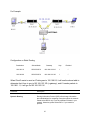
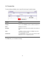
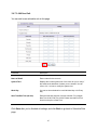
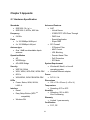
1
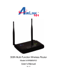
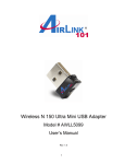
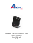
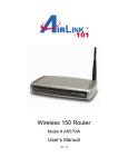
Wireless N 150 Green Router Model # AR570Wv2 User’s Manual Ver. 1A Copyright Copyright © Airlink101, 2012. The contents of this publication may not be reproduced in any part or as a whole, stored, transcribed in an information retrieval system, translated into any language, or transmitted in any form or by any means, mechanical, magnetic, electronic, optical, photocopying, manual, or otherwise, without the prior written permission. Trademarks All products, company, brand names are trademarks or registered trademarks of their respective companies. They are used for identification purpose only. Specifications are subject to be changed without prior notice. FCC Interference Statement This equipment has been tested and found to comply with the limits for a Class B digital device pursuant to Part 15 of the FCC Rules. These limits are designed to provide reasonable protection against radio interference in a commercial environment. This equipment can generate, use and radiate radio frequency energy and, if not installed and used in accordance with the instructions in this manual, may cause harmful interference to radio communications. Operation of this equipment in a residential area is likely to cause interference, in which case the user, at his own expense, will be required to take whatever measures are necessary to correct the interference. Table of Contents CHAPTER 1 PRODUCT INFORMATION..............................................................................................................1 1.1 INTRODUCTION AND SAFETY INFORMATION .........................................................................................................1 1.2 PACKAGE CONTENTS ...........................................................................................................................................2 1.3 FAMILIAR WITH YOUR NEW GREEN ROUTER ......................................................................................................3 CHAPTER 2 CONFIGURE THE ROUTER ............................................................................................................5 2.1 CONNECT THE ROUTER TO YOUR NETWORK .........................................................................................................5 2.2 CONFIGURE THE ROUTER WITH EZ SETUP WIZARD .............................................................................................7 2.3 CONFIGURE THE ROUTER WITH WEB CONFIGURATION UTILITY ........................................................................16 2.4 CONNECT TO ROUTER WIRELESSLY ...................................................................................................................24 CHAPTER 3 ADVANCED CONFIGURATION ....................................................................................................25 3.1 BASIC SETTING ..................................................................................................................................................27 3.1.1 Primary Setup ...........................................................................................................................................28 3.1.2 DHCP Server ............................................................................................................................................39 3.1.3 Wireless .....................................................................................................................................................41 3.1.4 Change Password......................................................................................................................................54 3.2 FORWARDING RULES ..........................................................................................................................................55 3.2.1 Virtual Server ............................................................................................................................................55 3.2.2 Special Applications..................................................................................................................................57 3.2.3 Miscellaneous............................................................................................................................................58 3.3 SECURITY SETTING ............................................................................................................................................60 3.3.1 Packet Filters ............................................................................................................................................60 3.3.2 Domain Filters ..........................................................................................................................................64 3.3.3 URL Blocking ............................................................................................................................................66 3.3.4 MAC Access Control .................................................................................................................................67 3.3.5 Miscellaneous............................................................................................................................................70 3.4 ADVANCED SETTING ..........................................................................................................................................72 3.4.1 System Time...............................................................................................................................................73 3.4.2 System Log ................................................................................................................................................75 3.4.3 Dynamic DNS............................................................................................................................................77 3.4.4 QoS Rule ...................................................................................................................................................78 3.4.5 SNMP ........................................................................................................................................................80 3.4.6 Routing......................................................................................................................................................81 3.4.7 Schedule Rule............................................................................................................................................84 3.5 TOOLBOX ...........................................................................................................................................................86 3.5.1 View Log....................................................................................................................................................87 3.5.2 Firmware Upgrade....................................................................................................................................88 3.5.3 Backup Setting...........................................................................................................................................89 3.5.4 Reset to Default.........................................................................................................................................89 3.5.5 Reboot .......................................................................................................................................................90 3.5.6 Miscellaneous............................................................................................................................................90 CHAPTER 4 STATUS...............................................................................................................................................91 4.1 SYSTEM STATUS .................................................................................................................................................92 4.2 WIRELESS STATUS..............................................................................................................................................92 4.3 STATISTICS INFORMATION ..................................................................................................................................92 4.4 NAT STATUS ......................................................................................................................................................93 CHAPTER 5 APPENDIX .........................................................................................................................................94 5.1 HARDWARE SPECIFICATION................................................................................................................................94 TECHNICAL SUPPORT..........................................................................................................................................95 Chapter 1 Product Information 1.1 Introduction and safety information Congratulations on your purchase of the Airlink101® AR570Wv2 Wireless N 150 Green Router. This Router is recommended to be used with AirLink101® Wireless N 150 products to provide the best performance. The high bandwidth combined with extended wireless coverage delivers fast and reliable connections for all of your networking applications. The Green power-saving technology intelligently reduces power consumption when no network activity is detected. A full range of security features such as WEP, WPA-PSK, and WPA2-PSK provide the highest level of wireless network security. The bundled EZ Setup Wizard allows you to set up the router with an easy-to-use user interface. Best of all, AR570Wv2 works with all 802.11n / g / b network devices which ensures compatibility with the existing wireless products. Other features of this router including: High wireless data rate of up to 150Mbps* with IEEE802.11n standard Fully backward compatible with 802.11 b/g Advanced NAT+SPI firewall with DoS detection provides secure protection for your network Wirelessly connects up to another 4 AR570Wv2 routers with WDS (Wireless Distribution System) supported Establishes secure wireless connection via Easy Setup Button (WPSTM compatible) Green Ethernet Technology minimizes power consumption QoS (Quality of Service) designed for prioritizing multimedia data transmission (i.e. VoIP, online gaming or movie streaming, etc.) Supports WEP, WPA-PSK/WPA2-PSK wireless security EZ Setup Wizard guides you through the router installation quickly and easily Supports multiple sessions IPSec and PPTP VPN pass-through Works best with other Airlink101® Wireless N products 1 1.2 Package Contents Before you start using this router, please check if there is anything missing in the package, and contact your dealer of purchase to claim for missing items: 1. 2. 3. 4. 5. Wireless N 150 Green Router with one un-detachable Antenna Power Adapter Setup CD Quick Installation Guide Ethernet Cable 2 1.3 Familiar with your new Green Router A. Front Panel LED Status Description Status Blinking (Green) Device is working properly. On (Green) Network device is connected Blinking Data access Off Not connected On (Green) Network device is connected Blinking Data access Off Not connected On (Green) Wireless feature is on Blinking Data access Blinking Rapidly Device is in WPSTM PBC mode Off Wireless feature is disabled WAN LAN 1~4 W.LAN Button Easy Setup Button (WPSTM compatible) Wireless On Description When Wireless is ON, press this button and release it immediately to start security synchronization function (WPSTM compatible). Press this button and hold it for about 1 sec. to turn on/off router’s wireless radio. 3 B. Back Panel Item Name Description Antennas These antennas are un-detachable 1.8dBi dipole antennas. 1-4 Local Area Network (LAN) ports 1 to 4. WAN Wide Area Network (WAN / Internet) port. RESET Press this button and hold for 4 seconds to restore factory default settings. PWR Power connector, connects to A/C power adapter. 4 Chapter 2 Configure the Router 2.1 Connect the Router to your network Note: Prior to connecting the router, be sure to power off your computer, DSL/Cable modem, and the router. Step 1 Connect one end of a network cable to the WAN port of the router and connect the other end of the cable to the DSL/Cable modem. Step 2 Power on the modem. Step 3 With another network cable, connect one end of the cable to your computer’s Ethernet port and connect the other end to one of the LAN ports of the router, as shown in the following figure. (After setup finishes, you can remove the network cable between the computer and router if you want to connect them wirelessly.) 5 Step 4 Plug the power adapter to the router and connect it to an electrical outlet. Step 5 Power on your computer. Step 6 Check LEDs of the router: make sure Status, WAN, W.LAN, and the LAN port that the computer is connected to are ON. 6 2.2 Configure the Router with EZ Setup Wizard Step 1 Insert the Setup CD into CD-ROM drive. Step 2 When the autorun menu pops up, click EZ Setup Wizard. Note: If the autorun menu does not show up on your monitor, please go to Computer Æ CDROM drive Æ Wizard, and execute “EZWizard.exe”. 7 Windows 7 and Vista users: An AutoPlay window pops up on screen. Please make sure you give permission to run the setup program by clicking Run Autorun.exe. Step 3 Select your language and click Next. 8 Step 4 Click on Wizard. Step 5 Please make sure your computer is connected to one of the 4 LAN ports of the router, and your modem is connected to the WAN port of the router. 9 Step 6 Click Next to configure the basic wireless settings. The default wireless encryption setting is disabled. It is suggested to select WPA2-PSK for best wireless security. Step 7 Configure the SSID (wireless network name, i.e. Airlink101), Channel, Security and Key. It is suggested to select WPA2-PSK for best wireless security. Enter 8~63 characters into Key box, then click Next. 10 Step 8 Click Next and the wizard will detect your WAN settings, or you can select your WAN type manually by checking “Let me select WAN service by myself”. Step 9 Enter the settings based on your WAN service type. Cable (Dynamic IP) If you are using cable Internet service, your WAN type is “Dynamic IP”. You do not need to configure anything here, and then click Next to continue. 11 DSL (PPPoE or Dynamic IP) For DSL users, your WAN type is either PPPoE or Dynamic IP. You can try both types and determine which one works for you. 12 For PPPoE connection, please enter the user name and password provided by your ISP (Internet Service Provider). Note: Depending on the ISP, you may need to include the domain name with your user name. Example: [email protected] Step 10 Verify the settings you have configured. Click Next to save the settings and reboot the router. This will take about 30 seconds. 13 Step 11 Click Next to test the Internet Connection, or you can ignore the test, just open the Internet browser and verify if your computer is connected to the Internet. Step 12 After the WAN service test is completed, click Finish. The wizard will open the web configuration page for the router automatically unless you uncheck “Open the default web browser to access the advanced configuration”. 14 You will see the status of the router on the web configuration page brought up by the web browser. Valid numbers should be assigned to IP Address, Subnet Mask and Gateway, instead of all 0’s. 15 2.3 Configure the Router with Web Configuration Utility Another approach to configure the router is using the Wizard in the Web Configuration Utility. The wizard will guide you setting up the basic settings of this router. You do not need to go through the wizard again if you have finished 2.2 Configure the Router with EZ Setup Wizard. In order to enter the Web Configuration Utility, you need to log into the router from your web browser first. Please follow the below steps: Step 1 Open the web browser (i.e. Internet Explorer or Mozilla Firefox) of the computer connected to the router and type 192.168.2.1 or the IP address you assigned to this router in the address bar and press Enter. Step 2 Enter the system password and click Login. (The default password is “admin”.) 16 Step 3 When you see this following page pops up, you have successfully logged into the router. Select Wizard and click on Enter to start the Setup Wizard. Step 4 Click Next to start the Setup Wizard. 17 Step 5 To change the System Password, enter the current password, new password and reconfirm the new password. (The default password is ‘admin’.) If you do not wish to change the password, please leave all fields blank. Click Next. Step 6 Select Auto Detecting WAN Type to let the Wizard detect which Internet connection you are using or select Setup WAN Type Manually to select the Internet connection type manually. Click Next. If you select Setup WAN Type Manually, please specify a WAN type you are using. 18 For Cable Users: Please select Obtain an IP address from ISP automatically (Dynamic IP Address). For DSL Users: You may select either Obtain an IP address from ISP automatically (Dynamic IP Address) or Some ISPs require the use of PPPoE to connect to their services (PPP over Ethernet) depending on the type of modem provided by your ISP (Internet Service Provider). You can try both settings and determine which one works for you. Click Save. 19 Step 7 Configure the WAN settings according to the WAN type you selected. Dynamic IP Address: Click on Clone MAC. PPP over Ethernet: Enter the Account and Password provided by your ISP. Note: Depending on the ISP, you may need to include the domain name with your user name. Example: [email protected] 20 Step 8 Keep the default SSID (wireless network name: Airlink101) or change it to a desired name, so you can always recognize your wireless network with it, for example ‘myHome’. Select a channel number for your wireless network. Click Next. Step 9 Set up Wireless Security for your router. It is recommended to select WPA2-PSK (AES) for security to protect your wireless network from unauthorized users. 21 Enter 8 to 63 characters into Preshare Key box. Click Next. WPA2-PSK (AES) is the most secure encryption mode for general users but some old wireless adapters may not support it. Therefore, please make sure all wireless devices on your network support this security type. Step 10 Verify the information you have configured. If everything is correct, click Apply Settings to save the settings and reboot router. 22 Step 11 When you see the below window, your router has been successfully connected to the Internet. Click Finish. Congratulations! Your router configuration has been finished. Please go to 2.4 Connect to the Router Wirelessly. 23 2.4 Connect to Router Wirelessly You must configure the wireless adapter from your computer in order to establish a wireless connection to the router. In this section, you can find the instructions of how to connect to the router wirelessly with your Windows 7 computer. You can also refer to the manual of your wireless adapter on how to connect to the router. Step 1 Click on the wireless icon in the system tray on your desktop. A list of available network will pop up. Select the one you want to connect to and click Connect. Step 2 Enter the key you configured for the router if you have enabled the wireless security, then click OK. Or, you can push Easy Setup Button on the router and wireless adapter for wireless security synchronization (Please refer to Section 3.1.3.2 for details). The wireless connection should be now established. 24 Chapter 3 Advanced Configuration You can make advanced configurations on this router through Web Configuration Utility to meet your network’s needs, such as: Virtual Server, Access Control, Network Security, etc. If you have already gone through the Setup Wizard, you do NOT need to configure anything here for you to start using the Internet. In order to enter the Web Configuration Utility of your router, you need to first log into the router from your web browser. Please follow the steps below: Step 1 From the computer that is connected to the router, open the web browser (i.e. Internet Explorer or Mozilla Firefox) and type 192.168.2.1 or the IP address you assigned to this router in the address bar and press Enter. Step 2 Enter the system password and click Login. (The default password is “admin”.) 25 Step 3 When you see this page pops up, you have successfully logged into the router. Select Advanced Setup and click Enter to access the complete features and settings of this router. 26 3.1 Basic Setting You can configure LAN, Internet connection type, DHCP, wireless settings and system password for the router in this page. 27 3.1.1 Primary Setup This page allows you to specify an IP address for your router, and configure the Internet connection settings. Parameter Description LAN IP Address The local IP address of this router. You can change it if necessary. WAN Type Displaying the current WAN (Wide Area Network, i.e. Internet) connection type you configured for the router. Click “Change” to modify. Please see Section 3.1.1.1. If you are not sure which WAN type you are using, please contact your ISP. IGMP The Internet Group Management Protocol (IGMP) is a communications protocol used by hosts and adjacent routers on IP networks to establish multicast group memberships. Virtual Computers Please find detailed instructions in Section 3.1.1.2. 28 3.1.1.1 WAN Type If you need to change router’s WAN type, please click Change in the Primary Setup menu. You will see the following page. Select a WAN type from the list and click Save. A. Static IP Address: Click on Static IP Address if your ISP (Internet Service Provider) has provided you a set of IP addresses for your Internet connection. B. Dynamic IP Address: Click on Dynamic IP if you are connecting to Internet through a cable modem. C. Dynamic IP Address with Road Runner Session Management: This setting only works when you are using Telstra Big Pond’s network service in Australia. D. PPP over Ethernet (PPPoE): Click on PPP over Ethernet if you are connecting to Internet through a DSL modem. Note: For DSL users, your WAN type is either Dynamic IP Address or PPP over Ethernet. If you are not sure which one you are using, it is suggested to select PPP over Ethernet for your WAN type, and if you cannot connect to the Internet with this setting, try to select Dynamic IP instead. Otherwise, you can call your ISP to confirm which WAN type you are using. E. PPTP: Some ISPs require the use of PPTP to connect to their services. F. L2TP: Some ISPs require the use of L2TP to connect to their services Please see the following instructions for settings of each WAN type: 29 A) Static IP Address Enter the WAN IP address, WAN Subnet Mask, WAN Gateway, Primary DNS , and Secondary DNS addresses provided by your ISP. After you’ve finished all settings, click Save to save the settings and click Reboot. The change will take effect after rebooting the router. 30 B) Dynamic IP Address Parameter Description Host Name Please input the host name of your router; this is optional and only required if your service provider asks you to do so. WAN’s MAC Address Please input MAC address of your computer here if your ISP only permits computer with certain MAC address to access Internet. If you are using the computer which used to connect to Internet via cable modem, you can simply press ‘Clone MAC’ button to fill the WAN’s MAC address field with the MAC address of your computer. Renew IP Forever Check Enable to let router reconnect to your ISP when the connection is dropped. After you’ve finished all settings, click Save to save the settings and click Reboot. The change will take effect after rebooting the router. 31 C) Dynamic IP Address with Road Runner Session Management: Please enter the account and password provided by your Telstra Big Pond ISP. Parameter Description Account Please input user name of your account assigned by Telstra. Password Please input the password assigned by Telstra. Login Server Please input the IP address of login server here. (Optional) After you’ve finished all settings, click Save to save the settings and click Reboot. The change will take effect after rebooting the router. 32 D) PPP Over Ethernet (PPPoE) Parameter Description PPPoE Account Enter the User Name for your DSL account. You can obtain this information from your ISP. PPPoE Password Enter the Password for your DSL account. You can obtain this information from your ISP. Primary DNS This feature allows you to assign a Primary DNS Server. You can obtain this information from your ISP. If your ISP does not provide this information, you can leave it blank. Secondary DNS This feature allows you to assign a Secondary DNS Server. You can obtain this information from your ISP. If your ISP does not provide this information, you can leave it blank. Maximum Idle Time This feature allows you to set up the amount of time of inactivity before disconnecting your PPPoE session. Set it to zero or 33 enable Auto-reconnect to disable this feature. Connection Control There are 3 modes for you to control the Internet connection: Connect-on-demand: Router will connect to the ISP when its clients send outgoing packets. Auto Reconnect (Always-on): Router will keep the connection to the ISP after the connection is established. Manually: Router will not connect to the ISP until user clicks the Connect button on the Status-page. PPPoE Service Name Enter the DSL service company. This is optional. Assigned IP Address Input the IP address you wish to use. This is optional. MTU (Maximum Transmission Unit) The most common MTU value is 1492. You can configure it as your ISP suggested. After you’ve finished all settings, click Save to save the settings and click Reboot. The change will take effect after rebooting the router. 34 E) PPTP Parameter Description IP Mode Select the type of how you obtain IP address from your service provider here: Static IP Address or Dynamic IP Address. My IP Address Enter the IP address assigned by your ISP if you select Static IP Address. My Subnet Mask Enter the Subnet Mask assigned by your ISP if you select Static IP Address. Gateway IP Enter the Gateway IP address assigned by your ISP if you select Static IP Address. Server IP Address/Name Enter the IP address of the PPTP server. PPTP Account Enter the User Name for your PPTP account here. You can 35 obtain this information from your ISP. PPTP Password Enter the password for your PPTP account here. You can obtain this information from your ISP. Connection ID Enter the connection ID if your ISP requires it. This is optional. Maximum Idle Time This feature allows you to set up the amount of time of inactivity before disconnecting your PPTP session. Set it to zero or enable “Auto-reconnect” to disable this feature. Connection Control There are 3 modes for you to control the Internet connection: Connect-on-demand: Router will connect to the ISP when its clients send outgoing packets. Auto Reconnect (Always-on): Router will keep the connection to the ISP after the connection is established. Manually: Router will not connect to the ISP until user clicks the Connect button on the Status-page. Maximum Transmission Unit (MTU) Most ISPs offer MTU value to users. The default MTU value is 0 (auto). 36 E) L2TP Parameter Description IP Mode Select the type of how you obtain IP address from your service provider here: Static IP Address or Dynamic IP Address. IP Address Enter the IP address assigned by your ISP if you select Static IP Address. Subnet Mask Enter the Subnet Mask assigned by your ISP if you select Static IP Address. WAN Gateway IP Enter the Gateway IP address assigned by your ISP if you select Static IP Address. Server IP Address/Name Enter the IP address of the L2TP server. L2TP Account Enter the User Name for your L2TP account here. You can obtain this information from your ISP. L2TP Password Enter the password for your L2TP account here. You can obtain 37 this information from your ISP. Maximum Idle Time This feature allows you to set up the amount of time of inactivity before disconnecting your L2TP session. Set it to zero or enable “Auto-reconnect” to disable this feature. Connection Control There are 3 modes for you to control the Internet connection: Connect-on-demand: Router will connect to the ISP when its clients send outgoing packets. Auto Reconnect (Always-on): Router will keep the connection to the ISP after the connection is established. Manually: Router will not connect to the ISP until user clicks the Connect button on the Status-page. Maximum Transmission Unit (MTU) Most ISPs offer MTU value to users. The default MTU value is 0 (auto). 3.1.1.2 Virtual Computers Virtual Computer enables you to use the original NAT feature, and allows you to set up the one-to-one mapping of multiple global IP addresses and local IP addresses. Parameter Description Global IP Enter the global IP address assigned by your ISP. Local IP Enter the local IP address (virtual IP address) of your LAN computer corresponding to the global IP address. Enable Check Enable box to enable the Virtual Computer mapping rule. 38 3.1.2 DHCP Server This page allows you to configure the DHCP settings for your router. Press button “More>>” for more options. Parameter Description DHCP Server Select to Disable or Enable the DHCP server. Lease Time This is DHCP dynamic IP lease time assigned to the DHCP clients. Please enter a number between 5 to10080. 10080 39 Minutes = 7 days. IP Pool Starting/Ending Address Whenever there is a request from a network client, the DHCP server will automatically allocate an unused IP address from the IP address pool to the requesting computer. You must specify a range by entering the starting / ending address of the IP address pool. Domain Name This is optional. This information will be passed to the clients. Primary DNS/Secondary DNS This is optional. This feature allows you to assign a Primary / Secondary DNS Server. Primary WINS/Secondary WINS This is optional. This feature allows you to assign a WINS Server. Gateway This is optional. Gateway address can be the IP address of an alternate Router. Clients List Click Clients List to view DHCP clients. Click Save to save the settings you made. 40 3.1.3 Wireless You can set parameters that are used for wireless clients to connect to this router. The parameters include SSID, Channel Number, Encryption, etc. Parameters Default Description Wireless Radio Enable Enable or disable wireless function. Wireless Off Schedule# Disable Select a pre-defined schedule rule from the drop-down menu and select Enable, then the router will turn on/off wireless function according to the schedule rule. Please refer to Section 3.4.7 for how to set up the Schedule Rule. Click on Disable to disable this feature if you want to keep wireless function always on. Network ID (SSID) Wireless Mode Airlink101 11b/g/n mixed This is the name of your wireless network. You can type any alphanumeric characters here, maximum 32 characters. SSID is used to identify your own wireless router from others when there are multiple wireless routers in the same area. It’s recommended to change default SSID value to the one that is easy to identify for you, such as “myhome”, “office_room1”, etc. Please select the wireless mode from one of the 41 following options: 11b/g/n mixed: 2.4GHz band, allows 802.11b, 802.11g, and 802.11n wireless network clients to connect to this router (maximum transfer rate 11Mbps for 802.11b clients, maximum 54Mbps for 802.11g clients, and maximum 150Mbps for 802.11n clients*). 11b Only: 2.4GHz band, only allows 802.11b wireless network clients to connect to this router (maximum transfer rate 11Mbps*). 11g Only: 2.4GHz band, only allows 802.11g wireless network clients to connect to this router (maximum transfer rate 54Mbps*). 11n Only: 2.4GHz band, only allows 802.11n wireless network clients to connect to this router (maximum transfer rate 150Mbps*). SSID Broadcast Channel Enable 11 Select Enable to broadcast the SSID so that your wireless client can detect it on the available wireless network list. Please select a channel from the drop-down list of ‘Channel Number’ for broadcasting. You can choose any channel number you want to use. WDS Please see 3.1.3.1 for WDS settings. WPS Please see 3.1.3.2 for WPS settings. Security You can choose None, WEP, 802.1x and RADIUS, WPA-PSK, WPA2-PSK, WPA, WPA2 for encryption mode. The detailed settings will appear after you choose an encryption. Please see below instructions for each Security type for more details. Wireless Client List Please see 3.1.3.3 for Wireless Client List information. 42 Configuring Security - WEP Note: IEEE802.11n only supports WPA2-PSK or WPA-PSK AES encryption. If you use WEP as your encryption, wireless data rate will drop to 54Mbps (802.11g standard). Key Mode: Select HEX or ASCII. You can select ASCII (alphanumeric format) or Hexadecimal (in the “a~f” and “0~9” range) for the key format. WEP: Key 1~4: Select 64 bits or 128 bits key length. Select a WEP Key you wish to use and enter key value. If you select HEX and 64 bits, enter a 10-digit Hex key, for example, “12345abcde”. If you select ASCII and 64 bits, enter a 5-digit ASCII key, for example, “xyz01”. If you select HEX and 128 bits, enter a 26-digit Hex key, for example, “12345abcde67890bcdef123456”. If you select ASCII and 128 bits, enter a 13-digit ASCII key, for example, “wepkeyexample”. 43 Configuring Security - WPA-PSK / WPA2-PSK Wi-Fi Protected Access (WPA) is an advanced security standard. You can use a pre-shared key (PSK) to authenticate wireless stations and encrypt data during communication, so the encryption key is not easy to be broken by hackers. This can greatly improve your wireless security.WPA2-PSK AES is the most secure setting for general users. Security: Encryption: Select WPA-PSK or WPA2-PSK Select either AES or TKIP. It is suggested to select AES if all your wireless devices support this encryption mode. Note: IEEE802.11n only supports AES encryption. If you use TKIP as your encryption, wireless data rate will drop to 54Mbps (802.11g standard). Preshare Key: Enter 8~63 characters as the security key of your wireless network. 44 Configuring Security – 802.1x and RADIUS When the 802.1x function is enabled, wireless users must authenticate this router first to use the network service. The most common method of implementing 802.1x is by having a RADIUS Server (contain an authentication database) on your LAN, so the router can work simultaneously with it and get user's authentication profile for comparison. Encryption Key Length: You can select either 64 bits or 128 bits. RADIUS Server IP: The RADIUS server's IP address. RADIUS port: The RADIUS server's service port. RADIUS Shared Key: Key value shared by the RADIUS server and this router. This key value should be consistent with the one in the RADIUS server. 45 Configuring Security - WPA / WPA2 Wi-Fi protected Access (WPA) is designed to improve data protection and implement access control for Wireless LAN system. It encrypts frames transmitted through wireless module using the key dynamically obtained from RADIUS Server. Encryption: Select either AES or TKIP. It is suggested to select AES if all your wireless devices support this encryption mode. RADIUS Server IP: The RADIUS server's IP address. RADIUS port: The RADIUS server's service port. RADIUS Shared Key: Key value shared by the RADIUS server and this router. This key value should be consistent with the one in the RADIUS server. After you finished all settings, click Save to save the settings and click Reboot. The change will take effect after rebooting the router. 46 3.1.3.1 WDS The Wireless Distribution System (WDS) provides wireless point-to-point, and point-to-multipoint bridging for deployment over large area. With the WDS feature, the Wireless LAN coverage can be easily extended. Note: WDS-enabled routers or APs from different manufacturers are not guaranteed to work with AR570Wv2. It is recommended to deploy WDS with solely Airlink101® AR570Wv2. When WDS is enabled, it only supports None and WEP encryption. Before you set up WDS bridging: 1) Make sure your wireless computer can associate with individual router/AP. 47 2) Configure the same channel for every router/AP. 3) Configure a unique different SSID for every router/AP in order to distinguish each unit on your wireless LAN. 4) Configure a static IP address for every router/AP. Make sure all IP addresses are based on the same subnet mask, and out of your DHCP client range. Parameters Description AP Mode AP Only: WDS function is disabled. WDS Only: The router is functioning as a bridge to connect with other WDS enabled AP/Router. Wireless client is not able to connect to the router at WDS Only mode. Hybrid: The router is functioning as a bridge as well as an AP that allows wireless client association at the same time. (Note: the data throughput is halved with Hybrid mode.) Remote AP MAC Enter the MAC address of other WDS enabled AP/Router into MAC 1 ~ MAC4. This feature allows you to bridge up to 4 AR570Wv2 routers. It is suggested to use “Copy to” function to avoid any typo. Scanned AP’s MAC Click on the drop-down menu to select an AP you wish to bridge to. Select a number from the drop-down menu of Remote AP MAC and click Copy to. The MAC address will be automatically filled into the corresponding MAC address field above. Scan AP Click Scan AP to find the available wireless Router/AP that you wish to bridge. If the wireless router/AP is not showing in the list, it may be out of range, and you need to move it closer in order to build the bridge connection. After you finished all settings, click Save to save the settings and click Reboot. The change will take effect after rebooting the router. 48 3.1.3.2 Easy Setup Button (WPSTM compatible) The AR570Wv2 Wireless N 150 Green Router has a built-in Easy Setup Button (WPSTM compatible) which allows you to build secured wireless connection between your wireless adapters and the router quickly and easily. Please make sure your wireless device supports this feature as well. If not, you will need to set up the wireless security manually and you can skip this section. In the instructions below, we are going to use the AWLL5099 Airlink101® Wireless N 150 USB Ultra Mini Adapter as an example. Note: You may have different wireless adapter installed in your computer. You can refer to the user’s manual from the manufacturer. Different adapters have different ways to trigger WPS configuration. Step 1 Connect wireless USB adapter to your computer with installed driver. Step 2 Push and hold the Easy Setup Button on the Adapter until you see the following window pops up on the screen. 49 Step 3 Within the following 1 minute, push the Easy Setup Button on the Router and hold for less than 1 second. The wireless LED will start blinking quickly. Step 4 The Router will now start the handshake with the wireless adapter, which will take about 30 seconds. When you see the window similar to the below one, the connection has been established. 50 To configure the WPSTM settings of the router, go to Advanced > Basic Setting > Wireless, and click on WPS “Enter” button. There are two methods to activate WPSTM with web configuration utility: PIN and PBC. 1) PIN (Personal Identification Number) You can check “Current AP PIN” and enter the numbers generated by this router displaying in “Current PIN of the device” to the wireless client. 51 Or, you can check “Configure Wireless Station”, and enter the PIN generated by the wireless client into Enrollee PIN, and then click Trigger button to start WPSTM. 2) PBC (Push Button Configuration) You can choose to press the hardware Easy Setup Button on the front panel of the router, or select Configure Wireless Station, Software button, and click Trigger button to start WPSTM. 52 Parameters Description WPS Select to Enable or Disable WPSTM function. WPS State It displays “Idle” when there is no WPS session going on, “Processing” when WPSTM is in progress, or “Complete” when WPSTM is finished. WPS Status It displays “Configured” if WPSTM setup is successful, or “Unconfigured” if WPSTM setup fails. Click Save after you’ve finished all settings. 3.1.3.3 Wireless Client List This table displays the wireless clients that are currently associated to the router. You can click Back to go back to the Wireless page, or click Refresh to refresh the list. 53 3.1.4 Change Password You can change the password required to log into the Router’s web configuration utility. The default password is “admin”. It is suggested to change the administrator’s default password as soon as you start to use the Router, and store it in a safe place. The password consists of 0 to 9 alphanumeric characters, and is case sensitive Parameters Description Old Password Enter the current password of the router. New Password Enter the new password. Reconfirm Enter the new password again for verification purposes. Note: If you forget your password, you’ll have to reset the router to the factory default (the default password is ‘admin’) by pressing the Reset button on the back panel of the router and hold for 4 seconds. Click Save after you’ve finished all settings. 54 3.2 Forwarding Rules You can configure Virtual Server, Special Application and Miscellaneous settings in this page. 55 3.2.1 Virtual Server If you want to host a HTTP/FTP server or allow remote access to your IP camera on the LAN from the Internet, you must set up port forwarding rules on the router in order to direct incoming traffic to the server or IP Camera. This page allows you to set up to 20 port forwarding rules for the specified applications. Parameter Description Well known services You can select a pre-defined service from the list of well known services, select a schedule rule, and the ID you wish to fill the settings in. Click Copy to and the settings you selected will be filled into the specific ID. Server IP This is the private IP address of the server behind the NAT firewall. Note: You must give your LAN client a fixed/static IP address for Virtual Server to work properly. Service Ports The range of ports to be forwarded to the Server IP. You can fill in a single port, such as 21, 80 or a range, such as 2000-2999. Protocol This is the protocol type to be forwarded. You can choose to forward “TCP” or “UDP” packets only or select “Both” to forward both “TCP” and “UDP” packets. 56 Enable Check to enable this forwarding rule. Schedule Rule# Enter a Schedule Rule number to enable the forwarding rule only within the desired time frame. Please refer to 3.4.7 Schedule Rule for detailed setting instructions. You can set 0 to enable the forwarding rule always. If you assign a schedule rule (for example, 9am to 5pm) to ID#1, users are only allowed to access the FTP server from 9am to 5pm. Next>> / Previous<< Access the next/previous 10 port forwarding rules. Click Save after you’ve finished all settings. 3.2.2 Special Applications Some applications require multiple connections, such as Internet gaming, video conferencing, Internet telephony and others. These applications cannot work when Network Address Translation (NAT) is enabled. If you need to run applications that require multiple connections, specify the port normally associated with an application in the “Trigger” field, and then enter the public ports associated with the trigger port to open them for inbound traffic. The range of the Trigger port is from 1 to 65535. 57 Parameter Description Popular applications You can select a pre-defined application from the list of Popular applications, and the ID you wish to fill the setting in. Click Copy to and the setting you selected will be filled into the specific ID. Trigger Enter an outbound port number assigned by the application. Incoming Ports When the trigger packet is detected, the inbound packets to the specified port numbers are allowed to pass through the NAT firewall, type in a range of incoming ports to be triggered, for instance, “5000-5300” or “9091, 9093-9100”. It depends on the special application’s requirement. Enable Check to enable this Special Application rule. Note: Only one PC can use each Special Application tunnel at same time. If the mechanism of Special Applications fails to make an application work, try setting your computer as the DMZ host instead, please refer to Section 3.2.3 Miscellaneous for details . Click Save after you’ve finished all settings. 3.2.3 Miscellaneous If you have a local client PC that cannot run an Internet application (e.g. Games) properly from behind the NAT firewall, then you can open the client up to unrestricted two-way Internet access by defining a DMZ Host. The DMZ function allows you to re-direct all packets going from your WAN port IP address to a particular IP address in your LAN. You can configure DMZ in this page, as well as UPnP and other settings. 58 Parameter Description IP Address of DMZ Host Enter the local IP address that you wish to open DMZ. If the application still doesn’t work on your computer after you open DMZ, you can try to enable Super DMZ for that computer. Super DMZ (IP Passthrough) Select Super DMZ when your computer or server on the Local Area Network needs to allow access from the Internet with a real public IP address. With IP Passthrough configured, all IP traffic, not just TCP/UDP, is forwarded back to the host computer. This can be necessary with certain types of software that do not function reliably through Network Address Translation. Hardware DMZ Port This feature allows the device to get Global IP from ISP directly. Some device like STB or MOD works via assigned Port. Non-standard FTP Port Enter the FTP port number if the FTP server’s port you try to access is not 21. UPnP Check the Enable box to enable UPnP feature. After you enable the UPnP feature, all client systems that support UPnP, like Windows 7, can discover this router automatically. Xbox Support Xbox is a video game console produced by Microsoft Corporation. Check the Enable box to enable Xbox Support feature Click Save after you’ve finished all settings. 59 3.3 Security Setting You can configure Internet access rules for your local computers based on Packet Filters, Domain Filters, URL Blocking, MAC Access Control and Miscellaneous settings in this page. 60 3.3.1 Packet Filters Packet Filters allows you to control access to a network by analyzing the incoming and outgoing packets and letting them pass or halting them based on the IP address of the source and destination. Outbound Filter applies to all outbound packets but Inbound Filter applies only to packets that are destined to Virtual Servers or DMZ host. If you want to restrict users from accessing certain Internet applications/services (e.g. Internet websites, email, FTP etc.) by their IP addresses, you can set up the filtering rules here. Packet filters can be helpful in securing or restricting your local network. Example: Computers with IP addresses between 192.168.2.20 to 192.168.2.50 have no restriction on accessing any network services, while other computers are all blocked. Meanwhile, computers with IP addresses between 192.168.2.100 to 192.168.2.199 are allowed to send Email (port 25), receive E-mail (port 110), and browse Internet (port 80). 61 For each rule, you can define: • • • • Source IP address Destination IP address Destination port address Protocol: TCP or UDP or both. Parameters Description Outbound Packet Filter Check/uncheck Enable to enable/disable the Packet Filtering. Outbound Filter applies to all outbound packets but Inbound Filter applies only to packets that are destined to Virtual Servers or DMZ host. Allow / Deny all to pass except Please select “Allow” or “Deny” to decide the behavior of packet those that match the following rules filtering table. If you select allow, all traffic will be allowed except that the Source IP addresses listed in filtering table will be rejected to connect to the destination IP addresses and ports. If you select deny, all traffic will be denied except that the Source IP address listed in filtering table will be allowed to connect to the destination IP addresses and ports. Source IP Please input the client’s IP address you wish to apply the filtering rule. You can input a single IP address (192.168.2.10) or a range of IP addresses (192.168.2.10-192.168.2.50). Leaving this field blank indicates all IP addresses. Destination IP Please input the Destination IP address (i.e. an FTP site, Email server, etc.) you wish to apply the filtering. You can input a single IP address (192.168.2.10) or a range of IP addresses (192.168.2.10-192.168.2.50), leaving this field blank means all IP addresses. Port Please input the port number here. You can define a single port (80) or a range of ports (1000-1999). Add prefix "T" or "U" to specify TCP or UDP protocol, for example, T80, U53, U2000-2999. No prefix indicates both TCP and UDP are defined. Leaving this field blank indicates all ports. Enable Check/uncheck Enable to enable/disable each Packet Filtering rule. Schedule Rule# Enter a Schedule Rule number to activate the filtering rule only within the desired time frame. Please refer to 3.4.7 Schedule 62 Rule for detailed setting instructions. Set 0 to let the filtering rule always take effect. Inbound Filter Click Inbound Filter button to go to Inbound Packet Filter settings. Click Save after you’ve finished all settings. Click Inbound Filter to configure inbound traffic filters. 63 3.3.2 Domain Filters You can block users from accessing specific domains on the internet. This feature can help parents to manage the Internet usage for their children (i.e. Parental Control). Parameter Description Domain Filter Check/Uncheck Enable box to enable/disable Domain Filter. Log DNS Query Check/Uncheck Enable box to enable/disable logging DNS Query. Privilege IP Address Range Enter a host IP address range that has privilege to access any network service without restriction. For example, From 10 to 20. Domain Suffix You can enter a domain suffix of URL to be restricted, for example, ".com" or "xxx.com". 64 Action Check Drop or Log or both to determine the actions of router, when user attempts to access the restricted domain. According to the settings in the screenshot above: Link request to www.abc.com will be dropped and recorded in log file. Link request to www.cde.com will be allowed but will be recorded in log file. Link request to www.fgh.com will be dropped and will not be recorded in log file. However, IP Address from 192.168.2.100 to 192.168.2.199 will not be restricted. Enable Check/Uncheck Enable box to enable/disable each rule individually. Schedule Rule# Enter a Schedule Rule number to activate the filtering rule only within the desired time frame. Please refer to 3.4.7 Schedule Rule for detailed setting instructions. Set 0 to let the filtering rule always take effect. Click Save after you’ve finished all settings. 65 3.3.3 URL Blocking You can block access to certain websites or web contents from local PCs by entering a full URL address or just keywords. The major difference between “Domain Filter” and “URL Blocking” is that Domain Filter requires user to input a suffix (like .com or .org, etc), while URL Blocking requires user to input a keyword only. In other words, Domain Filter can block specific websites, while URL Blocking can block any website that contains the specific keyword. This feature can also help parents to manage the Internet usage for their children (i.e. Parental Control). Parameter Description URL Blocking Check/Uncheck Enable box to enable/disable URL Blocking. URL You can enter the full URL address of a website or any keyword you want to block, for example “XXX”. Enable Check/Uncheck Enable box to enable/disable each URL 66 individually. Schedule Rule# Enter a Schedule Rule number to activate the filtering rule only within the desired time frame. Please refer to 3.4.7 Schedule Rule for detailed setting instructions. Set 0 to let the filtering rule always take effect. Click Save after you’ve finished all settings. 3.3.4 MAC Access Control MAC Access Control will help you to prevent unauthorized users from connecting to your wireless router. Only those network devices with MAC addresses you specified here are allowed to access your wireless router. You can utilize this function with other security measures described in previous sections together to enhance the safety of your wireless network. Before you configure any MAC control settings, you can set up to 3 administrative computers that will not be restricted by MAC Control rules. 67 In the Administrator MAC Control section, select a DHCP client computer from the drop-down list, select an ID, and click “Copy to”. The MAC address of the computer you selected will be automatically filled into the specific ID. Make sure the Enable box is checked. Click Save after you’ve finished all settings. In the Internet Access Control Section, click Next>> for detailed MAC Access Control configuration. Parameters Description MAC Access Control Check Enable box to enable the MAC filtering function. All settings in this page will take effect only when Enable is checked. Connection Control Check this box to enable the rule that wireless or wired clients whose MAC addresses are in the table can connect to the router. Choose "allow" or "deny" to determine whether the router allows or denies connection from other clients whose MAC addresses are not in the table. Association Control Check this box to enable the rule that only the wireless clients whose MAC addresses are in the table can associate to the 68 wireless LAN. If a client is denied to associate to the wireless LAN, it means it cannot send or receive any data via this router wirelessly. Choose "allow" or "deny" to determine if the router allows or denies wireless association from clients whose MAC addresses are not in the table. DHCP Clients Select a DHCP client from the drop-down list. Select an ID number and click Copy To. The client’s MAC address will be copied to the ID you selected; you do not need to enter it manually. MAC Address Input the MAC address of your computer / network device. C Check this box to allow the wired/wireless client to connect to the router. A Check this box to allow the wireless client to associate to the wireless network. Previous / Next You can set up to 32 MAC control rules for this router. Click Previous or Next to reach the previous or next 4 rules. Schedule Rule# Enter a Schedule Rule number to activate the filtering rule only within the desired time frame. Please refer to 3.4.7 Schedule Rule for detailed setting instructions. Set 0 to let the filtering rule always take effect. Click Save after you’ve finished all settings. 69 3.3.5 Miscellaneous Parameters Description Remote Administrator Host/ Port This feature enables you to perform administration task from remote host. If this feature is enabled, only the specified IP address can perform remote administration. Setting the specified IP address as 0.0.0.0 indicates any host can connect with this product to perform administration task. You can specify a port number for remote administrator; the default value is 88. Administrator Time-out The system will log out the administrator after no activity for a period of time. You may set the time-out period to zero to disable this feature. Discard PING from WAN side Check this box to enable Discard PING from WAN side. When you enable this feature, your router will not respond to a “ping” request from any host on the WAN side. SPI Mode Stateful Packet Inspection mode is a firewall that keeps track of the state of network connections (such as TCP, UDP communication) travelling across it. The firewall is programmed to distinguish legitimate packets for different types of connections. Only packets matching a known connection state will be allowed by the firewall; others will be rejected. 70 DoS Attack Detection Check this box to enable the DoS Attack Detection. Router will block the DoS once it is detected. Denial of Service (DoS) is a common attack measure, by transmitting a great amount of data or requests to your Internet IP address and server, so that the Internet connection will become very slow, and server may stop responding because it is not capable to handle too much traffic. VPN PPTP Pass-Through Check this box and the router will enable PPTP packets to pass through the router for VPN connection VPN IPSec Pass-Through Check this box and the router will enable IPsec packets to pass through the router for VPN connection. Click Save after you’ve finished all settings. 71 3.4 Advanced Setting This page allows you to set up System Time, System Log, Dynamic DNS, QoS Rule, SNMP, Routing, and Schedule Rule. 72 3.4.1 System Time To specify correct system time for your router is very important. It will affect the schedule rule and system logs. This router provides 3 ways to configure the system date and time: 1) Synchronize with time server. (The router must connect to the Internet.) > Select Get Date and Time by NTP Protocol 2) Synchronize with PC. > Select Set Date and Time using PC’s Date and Time 3) Manually configure the time ¾ Select Set Date and Time manually Parameter Description System Time Displaying the current system time of router. Sync Now Click this button to synchronize the system time with the desired 73 time server. (The router must be connected to the Internet to be able to synchronize time.) Time Server Select a time server here. Time Zone You can select your local time zone here. The router will synchronize time according to your time zone selection. PC Date and Time Select “Set Date and Time using PC’s Date and Time”, and router will automatically copy the date and time from your PC. Date / Time Select Year, Month, Day, Hour, Minute, and Second if you wish to set the system date and time manually. Daylight Saving Select Enable or Disable for daylight saving according to where you are located. Start / End If you enable daylight saving, please specify the first and last date of daylight saving time. Click Save after you’ve finished all settings. 74 3.4.2 System Log You can enable this function to log all important system events for your router. This page provides two methods to export system logs to specific destination by means of syslog (UDP) and SMTP (TCP). Parameters Description IP Address of Syslog Server Enter the host IP of destination where system log will be sent to. Check Enable box to enable this feature Email Alert Check Enable box if you want to enable Email Alert (send syslog via Email). Email Alert will work only if the router connects to Internet. Send Mail Now Click Send Mail Now to email system log to the account you set up. SMTP Server IP/Port Input the SMTP server IP and port, which are concatenated with 75 '/'. If you do not specify port number, the default value is 25. For example, "mail.abc.com" or "192.168.1.100/25". Email Addresses Enter the Email addresses of the recipients who will receive these logs. You can assign more than 1 recipient by using ';' or ',' to separate these Email addresses. Email Subject You may input the subject of email alert here. This setting is optional. Username Input the user name of Sender’s Email account. Password Input the password of Sender’s Email account. Log Type Select the types of communication you wish to log. View Log Click View Log to view all system logs. Click Save after you’ve finished all settings. 76 3.4.3 Dynamic DNS Parameter Description DDNS Select to Disable or Enable DDNS function. Provider A DDNS provider provides service for you to bind your IP (even private IP) with a certain Domain name. Choose a desired provider. Provider Website Click Provider Website to go to the selected DDNS provider’s website. Host Name You can register a domain name at the DDNS provider’s website. The full domain name is concatenated with host name (you specify) and a suffix (DDNS provider specifies). For example, ABChome.dyndns.org. Username / E-mail This field is required by DDNS provider to authenticate its users. Input user name you registered at the DDNS provider. Password / Key This field is required by DDNS provider to authenticate its users, too. Input password or key according to the DDNS provider you select. Click Save after you’ve finished all settings. 77 3.4.4 QoS Rule Quality of Service provides an efficient way for computers on the network to share the Internet bandwidth with a promised quality of Internet service. Without QoS, all computers and devices on the network will compete with one another to get Internet bandwidth, and some applications which require guaranteed bandwidth (like video streaming and network telephone) will be affected; therefore, an unpleasing result will occur, such as interruptions to video / audio streaming. Parameter Description QoS Control Check Enable box to enable QoS function. Well known services Select a network service, a schedule rule and ID#, and click “Copy to”. The settings you selected will be filled into the specific ID. Local IP Specify a local (source) IP address that will be affected by this 78 rule. Remote IP Address Specify a remote (destination) IP address that will be affected by this rule. Ports Please input the range of remote (destination) port number that will be affected by this rule. If you want to apply this rule on port 80 to 90, please input “80-90”; if you want to apply this rule on a single port, just input the port number, such as 80. If the remote (destination) IP address and /or port number is universal, just leave it blank. QoS Priority Assign High, Normal, or Low priority to the specific network client. Enable Check this box to enable individual QoS rule. Schedule Rule# Enter a Schedule Rule number to activate the QoS rule only within the desired time frame. Please refer to 3.4.7 Schedule Rule for detailed setting instructions. Click Save after you’ve finished all settings. 79 3.4.5 SNMP Configure the router to allow administrative computers to control it through SNMP(Simple Network Management Protocol). Parameter Description Enable SNMP You must check either Local or Remote or both to enable SNMP function. If Local is checked, this device will respond to requests from LAN. If Remote is checked, this device will respond to requests from WAN. Get Community Setting the community of GetRequest your device will respond to. Set Community Setting the community of SetRequest your device will accept. IP 1~4 Input your SNMP Management PC's IP here. User has to configure where this device should send SNMP Trap message to. SNMP Version Please select proper SNMP Version that your SNMP Management software supports. Click Save after you’ve finished all settings. 80 3.4.6 Routing Routing Table allows you to determine which physical interface address to use for outgoing IP data grams. If you have more than one router and subnet, you will need to enable routing table to allow packets to find proper routing path and allow different subnets to communicate with each other. For static routing, you can specify up to 8 routing rules. You can enter the destination IP address, subnet mask, gateway, and hop for each routing rule, and then enable or disable the rule by checking or un-checking the Enable checkbox. 81 For Example: AR570Wv2 Configuration on Static Routing Destination Subnet Mask Gateway Hop Enabled 192.168.1.0 255.255.255.0 192.168.123.216 1 √ 192.168.0.0 255.255.255.0 192.168.123.103 1 √ When Client3 wants to send an IP data gram to 192.168.0.2, it will use the above table to determine that it has to go via 192.168.123.103 (a gateway), and if it sends packets to 192.168.1.11, it will go via 192.168.123.216 Parameter Description Dynamic Routing Routing Information Protocol (RIP) will exchange information about destinations for computing routes throughout the network. Please select RIPv2 only if you have different subnets in your network. Otherwise, please select RIPv1 if you need this protocol. 82 Static Routing Select Enable or Disable to enable or disable Static Routing function. Destination Enter a destination IP address. The Destination IP is the address of the remote network or host to which you want to assign a static route. Subnet Mask Enter the subnet mask. The Subnet Mask determines which portion of a Destination IP address is the network portion, and which portion is the host portion. Gateway Enter the gateway IP address. This is the IP address of the gateway device that allows for contact between the Router and the remote network or host. Hop Specify the number of next hop. Enable Check or uncheck Enable box to enable or disable the static routing rule. Click Save after you’ve finished all settings. 83 3.4.7 Schedule Rule You can configure schedule rules to control the time frame of network access. Parameter Description Schedule Check or uncheck Enable to enable or disable the schedule rule. Rule# Displaying rule numbers. Rule Name Displaying rule names that have been added to the schedule rule table. Action Click Edit to modify the schedule rule or Delete to remove the rule from the schedule rule table. Add New Rule Click Add New Rule to add a new rule to the schedule rule table. Please refer to 3.4.7.1 for detailed instructions. Click Save after you’ve finished all settings. 84 3.4.7.1 Add New Rule You can add a new schedule rule in this page. Parameter Description Name of Rule# Enter a name for the new rule. System Time Displays the current system time of the router for you to verify if this matches the date/time of where you are located. You can refer to 3.4.1 on how to modify the system time. Week Day You can set time schedule for each individual day or for Every Day. Start Time/End Time (hh:mm) Enter the start and end time of a time schedule. For example, Start Time 01:00, End Time 23:00. Please note that End Time should not be prior to Start Time. Click Save after you’ve finished all settings, and click Back to go back to Schedule Rule page. 85 3.5 Toolbox The Toolbox page allows you to view system logs, upgrade firmware, save/reload configuration settings, reset factory default settings, reboot the router, and perform ping test. 86 3.5.1 View Log You can view, download, and clear the system logs stored in the router here. 87 3.5.2 Firmware Upgrade You can view the current firmware version of router in this page. To upgrade the firmware for the router, you must use a computer that is wired connected to the router. You need to download the firmware from www.airlink101.com and save it to your local hard disk first. You may need to unzip it if it is a .zip file. Click Browse to select the firmware you just downloaded/unzipped, and then click Upgrade to start the upgrade process. (You may have to wait for a few minutes for the upgrade to complete). NOTE: Never interrupt the upgrade process by closing the web browser or disconnect your computer from router. If the firmware you uploaded is corrupt, the firmware upgrade will fail, and you may contact Technical Support for help. 88 3.5.3 Backup Setting You can save the router’s configuration settings to your local hard disk by clicking Backup Setting and save it as a .bin file. Once you need to restore the settings, please go to Firmware Upgrade page and load the .bin file you’ve saved. 3.5.4 Reset to Default To restore the router settings to factory default, click Reset to Default, and you will be prompted: Click OK to continue or Cancel to exit. 89 3.5.5 Reboot To reboot the router, click Reboot, and you will be prompted: Click OK to continue or Cancel to exit. 3.5.6 Miscellaneous Parameter Description MAC Address for Wake-on-LAN Wake-on-LAN is a technology that enables you to power up a networked device remotely. In order to use this feature, the target device must be Wake-on-LAN enabled and you have to know the MAC address of this device. Enter the MAC address of the device and click Wake Up. The router will send wake-up frame to the target device immediately and the device can be powered up remotely. Domain Name or IP Address for Ping Test Enter a domain name (i.e. google.com) or IP address to perform ping test. If you can ping a remote website, it means the Internet is connected. Click Save after you’ve finished all settings. 90 Chapter 4 Status The Status section allows you to monitor the current status of your router. You can use the Status page to monitor: the Internet connection, Wireless, NAT status, and the statistics information of the Router. 91 4.1 System Status You can view the status of current Internet connection. By clicking Renew and Release, you can renew and release the WAN IP address obtained from the ISP (Internet Service Provider). And you may go back to Primary Setup page to edit the Internet connection settings by clicking Edit. 4.2 Wireless Status You can view the Wireless LAN status of your router, including SSID (the name of your wireless network), Channel number, Security, and Wireless MAC address of the router. And you may go back to Wireless Setting page to edit wireless settings by clicking Edit. 4.3 Statistics Information You can view the statistics information of your router, including inbound and outbound packets. 92 4.4 NAT Status Click NAT Status on the bottom of the Status page to view NAT Status. 93 Chapter 5 Appendix 5.1 Hardware Specification Standards Advanced Features • IEEE 802.11b / g / n • IEEE 802.3, 802.3u, 802.3ab Frequency • NAT - Virtual Server - IPSEC/PPTP VPN Pass Through - DMZ Host - Special Application - Super DMZ • SPI Firewall - IP/Service Filter - MAC Control - URL Blocking - Domain Name Filter - DoS Protection - SPI Mode • 2.4GHz Ports • 1 x 10/100Mbps WAN port • 4 x 10/100Mbps LAN port Antenna type • One 1.8dBi un-detachable dipole antenna Operation Modes • AP • WDS Bridge • AP+WDS Bridge Security • • • • LEDs • System Requirement • Windows®, Mac®, or Linux® operating system WEP 64/128-bit WPA, WPA2, WPA-PSK, WPA2-PSK • Installed Ethernet adapter Power 802.1x WPA/WPA2, WPA-PSK/WPA2-PSK • DC 5V / 1A Dimensions Power, Status, WAN, WLAN, LAN1~4 Interface Reset Easy Setup Button (WPS TM compatible) Wireless ON • 156 x 110 x 22 mm (L x W x H) Temperature • Operating: 0ºC to 40ºC Humidity • Operating: 10% to 90% Non-Condensing Warranty • Limited 1-year warranty Certification • 94 FCC, CE Technical Support E-mail: [email protected] Toll Free: 1-888-746-3238 Website: www.airlink101.com *Theoretical maximum wireless signal rate derived from IEEE standard 802.11N specifications. Actual data throughput will vary. Network conditions and environmental factors, including volume of network traffic, building materials and construction, mix of wireless products used, radio frequency interference (e.g., cordless telephones and microwaves) as well as network overhead lower actual data throughput rate. Compatibility with 802.11n devices from other manufactures is not guaranteed. Specifications are subject to change without notice. Photo of product may not reflect actual content. All products and trademarks are the property of their respective owners. Copyright ©2012 Airlink101® **Wi-Fi® is a registered trademark and WPSTM is a trademark of the Wi-Fi alliance® 95