1
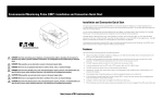
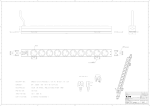
The EMP measures relative humidity from 10% to 90% with an accuracy of ±5%.
S
S
S
S
S
S
S
S
The EMP monitors temperature and humidity information of any environment that you want to protect your critical
equipment. The EMP measures temperatures from 0°C to 70°C with an accuracy of ±2°C.
S
When temperature and humidity values exceed user-selectable limits, the event is logged in the ePDU event history log.
Changes in external contact status are logged in the ePDU event history log.
E-mail notification through Simple Mail Transfer Protocol (SMTP), using e-mail client software when acceptable alarm
limits are exceeded or contact status changes.
User-selectable alarm thresholds enable you to define acceptable temperature or humidity limits.
Temperature, humidity, and contact closure status can be displayed through a Web browser, a Serial interface, or an
onboard LCD interface.
The EMP monitors the status of the two user-provided contact devices.
It can be located away from the ePDU with a CAT5 network cable up to 20 m (65.6 ft) long.
The hot-swap feature simplifies installation by enabling you to install the probe safely without turning off power to the
ePDU or to the loads that are connected to it.
S
http://www.ePDU.com/countries.php
open the device covers, unless instructed otherwise in the installation and configuration procedures.
CAUTION: Disconnect the attached power cords, telecommunications systems, networks, and modems before you
CAUTION: Never turn on any equipment when there is evidence of fire, water, or structural damage.
CAUTION: When possible, use one hand only to connect or disconnect signal cables.
open the device covers, unless instructed otherwise in the installation and configuration procedures.
DANGER: Disconnect the attached power cords, telecommunications systems, networks, and modems before you
DANGER: Never turn on any equipment when there is evidence of fire, water, or structural damage.
DANGER: When possible, use one hand only to connect or disconnect signal cables.
disconnect any cables or perform installation, maintenance, or reconfiguration of this product during an electrical
storm.
DANGER: Electrical current from power, telephone, and communication cables is hazardous. Do not connect or
The environmental monitoring probe has the following features:
Features
For detailed information about using the EMP, refer to the Eaton Advanced Enclosure Power Distribution Unit (ePDU) User’s
Guide. Access the User’s Guide at http://www.ePDU.com/countries.php.
The EMP device is delivered with a screw, Velcro fasteners, tie wraps, and a connection cable. You can install the device
anywhere on the rack. To attach the EMP, use either the Velcro fasteners or mount the EMP on the supplied screw. The EMP
also has a universal slot on the back for mounting easily on a screw and in any direction.
You can monitor readings locally using the onboard LCD menu display, or remotely using a Telnet connection or a standard
Web browser. This provides greater power management control and flexible monitoring options.
The optional environmental monitoring probe (EMP) is a connectivity device that enables you to collect temperature and
humidity readings in the rack environment and monitor the environmental data remotely. You can also collect and retrieve the
status of two contact devices.
Installation and Connection Quick Start
Environmental Monitoring Probe (EMP) Installation and Connection Quick Start
2
7
Refer to the Network Connections Quick Start (packaged with the ePDU) for initial network configuration information. For
more detailed information, refer to the Eaton Advanced Enclosure Power Distribution Unit (ePDU) Firmware User's Guide at
http://www.ePDU.com/countries.php.
NOTE: On startup, the ePDU automatically recognizes the EMP.
When you are ready to configure EMP thresholds, start up the ePDU.
6
S
Use either the supplied screw or Velcro straps to mount the EMP in a convenient location anywhere on the rack as
follows:
NOTE: If the supplied cable is not long enough for your installation, you can use another Ethernet cable up to a length of 20m (65.6 ft).
http://www.ePDU.com/countries.php
Queda estrictamente prohibida cualquier forma de reproducción sin el previo consentimiento de Eaton Corporation por escrito. Eaton y el logo de Eaton son marcas comerciales de Eaton Corporation. Eaton niega el interés en el derecho de propiedad de las marcas y nombres comerciales de terceros. 05/2011 • P-164000046 Rev 1
La información de este documento se encuentra sujeta a cambios sin previo aviso. © 2011 Eaton Corporation Inc. Todos los derechos reservados.
Eine Vervielfältigung, gleich welcher Art, ist ohne schriftliche Genehmigung von Eaton Corporation strengstens untersagt. Bei Eaton und dem Eaton-Logo handelt es sich um Marken von Eaton Corporation. Eaton verzichtet auf die Beteiligung am Urheberrecht an den Marken und Namen Dritter. 05/2011 • P-164000046 Änd 1
Die Angaben in diesem Dokument unterliegen unangekündigten Änderungen. © 2011 Eaton Corporation Inc. Alle Rechte vorbehalten.
La reproduction de ce document de quelque manière que ce soit sans l'autorisation écrite de Eaton Corporation est strictement interdite. Eaton et le logo Eaton sont des marques commerciales de Eaton Corporation. Eaton nie tout intérêt propriétaire dans les marques commerciales et les noms commerciaux ne lui appartenant pas. 05/2011 • P-164000046 1
Les informations de ce document sont susceptibles d'être modifiées sans préavis. © 2011 Eaton Corporation Inc. Tous droits réservés.
Normally Open
Normally Closed
Normally Open
Normally Closed
Normally Closed
Locate the Ethernet cable (supplied). Connect one end of the cable to the RJ-45 connector on the EMP, then connect
the other end of the cable to the RS-232 connector on the ePDU (see Figure 2).
Contact 2 returns
Contact 2 signal inputs
4
2
3
Contact 1 returns
Contact 1 signal inputs
1
Normally Open
To mount the ePDU within the enclosure environment, attach one Velcro fastener to the ePDU and the other
Velcro fastener to an enclosure rail post. Press the two Velcro strips together to secure the EMP to the rail post.
S
The EMP has a universal slot on the rear for easy mounting on a screw in any direction. Use the supplied screw
to wall mount the EMP.
Use the supplied tie wraps to secure the Ethernet cable out of the way as needed.
5
4
Device 2 Connection
Device 1 Connection
Pin Number
Connect the first external contact device between pin number 1 and pin number two (above label 1; see Figure 1).
Connect the second external contact device between pin number 3 and pin number 4 (above label 2; see Figure 1) as
follows:
NOTE: External contact devices can be normally open or normally closed.
If you plan to monitor one or two external contact devices, connect the external contact closure inputs to the screw
terminals on the EMP.
Device
3
2
Reproduction in any manner whatsoever without the written permission of Eaton Corporation is strictly forbidden. Eaton and the Eaton logo are trademarks of Eaton Corporation. Eaton disclaims proprietary interest in the marks and names of others. 05/2011 • P-164000046 Rev 1
Information in this document is subject to change without notice. © 2011 Eaton Corporation Inc. All rights reserved.
1
Please have the following information ready when you call the Eaton Customer Support Center: Model number, serial number,
symptoms of failure or problem, customer return address, and contact information. If repair is required, you will be given a
Returned Material Authorization (RMA) Number. This number must appear on the outside of the package and on the Bill of
Lading (if applicable). Use the original packaging or request packaging from the Eaton Customer Support Center or distributor.
Units damaged in shipment as a result of improper packaging are not covered under warranty. A replacement unit will be
shipped, freight prepaid for all units under warranty.
United States:
1.800.356.5737
All other countries: Contact your local service representative.
For questions or problems, please call your local distributor or the Eaton Customer Support Center at one of the following
telephone numbers and ask for an ePDU technical representative.
Service and Support
To install the optional EMP:
Inspect the product before installation. If the product is damaged in any way, see the Service and Support section for more
information.
Locate the EMP (purchased separately).
You can install the EMP either before or after ePDU installation and startup. An EMP can be installed without turning off
power to the ePDU or the devices connected to it.
The EMP is an optional accessory that is packaged separately from the ePDU. Use proper lifting and carrying techniques when
unpacking and moving the EMP packing carton and components.
1
Connecting the Optional EMP to the ePDU
Unpacking and Inspecting the Equipment