1
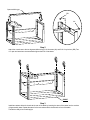
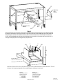
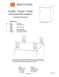
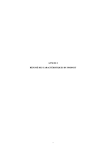
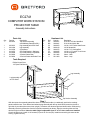
EC2741
COMPUTER WORK STATION /
PROJECTOR TABLE
Assembly Instructions
Parts List
Qty.
1
Part No.
022-2014
1
1
1
1
1
2
2
022-2013
022-1694
010-2336
010-3273
010-3058
015-0002
015-0003
Description
Top Section Assembly
(with Modesty Panel/Wire Bin)
Leg Assembly with CPU Shelf
Leg Assembly
Cross Brace
CPU Side Bracket - Stationary
CPU Side Bracket - Adjustable
4" Swivel Caster-Rear
4" Swivel Caster with Brake-Front
Qty.
2
2
8
8
2
2
4
2
2
Ref.
AA
BB
CC
DD
EE
FF
GG
HH
II
Hardware List
Part No.
030-0307
030-0421
030-0253
030-0120
030-0272
030-0325
030-0256
031-1822
031-1823
Description
5/16-18 x 5/8" Hex Head Bolt
5/16-18 Hex Nylock Nut
1/4-20 x 3/4" Combo Head Screw
1/4-20 Square Nut
1/4-20 x 1/2" Carriage Bolt
1/4-20 x 1/2" Combo Truss Screw
1/4-20 Flange Nut
Velcro - Hook
Velcro - Loop
Tools Required
Phillips Screw Driver
1/2" Open End Wrench
Leg Assembly
Leg Assembly
w/ CPU Shelf
DD
CC
Top Section Assembly
Step 1
With the top section assembly placed face down on a carpeted surface (or cardboard), position the modesty
panel toward the rear. Then determine whether the leg assembly with the cpu shelf will be located on the left or
right side of your table (when turned over upright). The above view shows a right hand shelf location. Slide one leg
assembly into the leg extensions from the top section assembly as shown. Align the mounting holes until the
desired height is achieved. Note: the table height is adjustable from 27" to 41" when casters are installed.
Once the height is set, install 1/4-20 screws (CC) and 1/4-20 nuts (DD). Install the second leg the same as the
first leg. Tighten securely.
Open end facing up
BB
AA
Step 2
Attach the cross brace to the two leg assemblies using 5/16-18 screws (AA) and 5/16-18 nylock nut (BB). Two
1/2" open end wrenches recommended to tighten the 5/16-18 hardware.
FRONT
Step 3
Install two casters without the brake at the rear of the table by inserting the stem of the caster into the sockets
of leg assembly base. Repeat the same for the two casters with the brake at the front of the table.
The table is ready to be turned upright.
FF
Stationary
CPU
Bracket
EE
Adjustable CPU
Bracket
GG
Step 4
When mounting the cpu brackets, the first set of mounting holes to the front edge of the cpu shelf are utilized
whether the side shelf is mounted on the left or right side of the table. Attach stationary cpu side bracket with
flange facing the exterior of the table and secure with 1/4-20 screws (FF) and 1/4-20 flanged nuts (GG) as
shown. Attach adjustable cpu side bracket with flange facing the exterior of the table and secure with 1/4-20
carriage screws (EE) and 1/4-20 flanged nuts (GG) as shown.
II
HH
II
HH
Step 5
Attach two pieces of velcro-hook (HH) and loop (I I) to each cpu brackets interior surface as shown. This will
hold your cpu in place by keeping it from moving forward or backward on the shelf.
Bretford
11000 Seymour Avenue
Franklin Park, IL 60131
TEL: 847.678.2545
800.521.9614
FAX: 847.678.0852
800.343.1779
Bretford Ltd.
Technology House
7 Lake End Court, Taplow
Bucks SL6 0JQ England
TEL: 01628 603558
FAX: 01628 604923
www.bretford.com
Part #031-3359
Rev. 06.03.05 CH