1
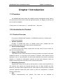
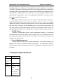
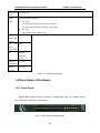
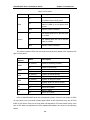
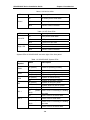
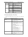
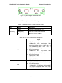
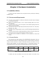
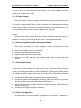
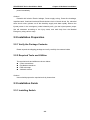
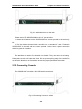
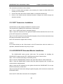
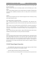
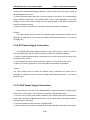
SS3GR1028F Series Installation Guide Content Content CHAPTER 1 INTRODUCTION....................................................1-1 1.1 OVERVIEW ..........................................................................................1-1 1.2 INTRODUCTION TO PRODUCT ................................................................1-1 1.2.1 Product Overview ................................................................................. 1-1 1.2.2 Features and Benefits .......................................................................... 1-1 1.3 PHYSICAL SPECIFICATIONS ..................................................................1-2 1.4 DESCRIPTION OF HARDWARE ...............................................................1-3 1.4.1 Front Panel ............................................................................................ 1-3 1.4.2 Back Panel............................................................................................. 1-4 1.4.3 DC Power/PoE Power Input ................................................................. 1-4 1.4.4 Status LEDs........................................................................................... 1-4 1.4.5 Interface Description of Front Panel ................................................... 1-7 1.4.6 SS3GR10XFP/SS3GR10SFP+ Extended Module Description ........... 1-8 CHAPTER 2 HARDWARE INSTALLATION ...............................2-1 2.1 INSTALLATION NOTICE .........................................................................2-1 2.1.1 Environmental Requirements .............................................................. 2-1 2.1.2 Installation Notice ................................................................................. 2-4 2.1.3 Security Warnings ................................................................................ 2-4 2.2 INSTALLATION PREPARATION ...............................................................2-5 2.2.1 Verify the Package Contents................................................................ 2-5 2.2.2 Required Tools and Utilities................................................................. 2-5 2.3 INSTALLATION GUIDE ..........................................................................2-5 2.3.1 Installing Switch.................................................................................... 2-5 2.3.2 Connecting Console ............................................................................. 2-6 2.3.3 SFP Transceiver Installation ................................................................ 2-7 2.3.4 SS3GR10XFP Extended Module Installation ...................................... 2-7 2.3.5 SS3GR10SFP+ Extended module Installation .................................... 2-8 2.3.6 SS3GR10SFP Extended module Installation ...................................... 2-8 2.3.7 Copper Cable/Fiber Cable Connection ............................................... 2-8 2.3.8 AC Power Supply Connection ............................................................. 2-9 2.3.9 DC Power Supply Connection ........................................................... 2-10 2.3.10 PoE Power Supply Connection........................................................ 2-10 1 SS3GR1028F Series Installation Guide Chapter 1 Introduction Chapter 1 Introduction 1.1 Overview The SS3GR1028F series switch are intelligent network management switch used by the network environment which needs the high performance, the bigger port density and the convenient installation. 12 fiber ports+12 Combo ports+2 extended cards +DC power 1.2 Introduction to Product 1.2.1 Product Overview Front panel of SS3GR1028F supplies 12 1000M-fiber-ports and 12 Combo ports. Features and Benefits Various Interfaces Provides 12 1000Mb fiber ports, 12 1000Mb Combo ports (1000Mb fiber SFP ports/1000Mb copper ports) and 2 slots with the extended cards. Secure Power Supply Provides DC/AC power backup, support 220V AC input, 48V DC input or 220V AC, 48V DC input simultaneously. Support 10Gb Ethernet 10Gb Ethernet which adopts full-duplex technology instead of low-speed, half-duplex CSMA/CD protocol, is a big leap in the evolution of Ethernet. 10Gb Ethernet can be deployed in star or ring topologies. Provide broad bandwidth and powerful processing capacity. It is suitable for metropolitan networks and wide area networks. Users can simplify network structures and reduce cost of network construction. Networking Protocols Supports 802.1d/w/s, 802.1Q, 802.1p, 802.3ad, 802.3x, GVRP, DHCP and SNTP etc. The switches also support the multicast protocols such as IGMP, DVMRP and PIM. Moreover, this switch series supports RIPv1/2, OSPF, BGP and IPv6 protocols. All these protocols supported enable this switch series to meet the requirements of complex network constructions. ACL Support comprehensively ACL policies. 1-1 The traffic can be classified by SS3GR1028F Series Installation Guide Chapter 1 Introduction source/destination IP addresses, source/destination MAC addresses, IP protocols, TCP/UDP, IP precedence, time ranges and ToS. And various policies can be conducted to forward the traffic. By implementing ACL policies, users can filter the virus packets such as “Worm.Blaster”, “Worm.Sasser” and “Red Code” etc. Also supports IEEE802.1x port based access authentication, which can be deployed with RADIUS, to ensure the port level security and block illegal users. QoS Fully supports DiffServ Module. Users can specify a queue bandwidth on each port. WRR/SP/SWRR scheduling is also supported. Support the port trust. Users can configure trusted CoS, DSCP, IP precedence and port priority. User can also modify packet’s DSCP and COS values. The traffic can be classified by port, VLAN, DSCP, IP precedence and ACL table. User can also modify packet’s DSCP and IP precedence values. Users can specify different bandwidths for voice/data/video to customize different qualities of service. 3D-SMP Ready Supports a self-defending security region management strategy. It is supported interaction with some security system such as firewall, IDS, etc. It can defense the virus and aggress effectively from the extranet and internet. Thus enhance the security and stability of the network-wide. Perfect Web Management. Support SNMP, In-band and Out-of band Management, CLI and WEB interface and RMON. It can mail the correlative sensitive information to the administrator abide by SMTP protocol. Support SSH protocol, ensure the configuration management security of the switch. 1.3 Physical Specifications Item SS3GR1028F Dimension 440×324×44 (W * H * D) (mm) Weight <6kg Fixed ports 12 SFP fiber ports 12 1000Mb Combo ports 2 interfaces with extended card 1-2 SS3GR1028F Series Installation Guide Management Chapter 1 Introduction 1 Console port ports System Supports AC/DC power input: power z AC input: The rating voltage range: 100V~240V AC; 50/60HZ The max voltage range: 90V~264V AC; 47HZ~63HZ DC input: z 48V DC input, -48V~-60V/DC; 2.5A Output Do not support power supply of PoE The max 35W Power Consumption Fan Support automatic timing 0℃~50℃ Operating Temperature Relative 10%~90% Humidity Table 1-1 Physical Specifications 1.4 Description of Hardware 1.4.1 Front Panel SS3GR1028F Ethernet switch provides 12 1000Mb fiber ports, 12 1000Mb Combo ports, 8 function LEDs and 1 Console port. Fig 1-1 Front Panel of SS3GR1028F 1-3 SS3GR1028F Series Installation Guide Chapter 1 Introduction 1.4.2 Back Panel SS3GR1028F supplies 2 interfaces with the extended card, 1 interface with -48V DC power input and 1 interface with 220V AC power input. Fig 1-2 Back Panel of SS3GR1028F 1.4.3 DC Power/PoE Power Input Supports AC/DC input power backup and PoE power output. pin-outs signal of DC power and PoE power are distributed as below: Fig 1-3 Pin-outs Distribution of DC Input SS3GR1028F There are 3 pin-outs for DC socket: PIN1: GND Ground connection PIN2: -48V DC power cathode input PIN3: 0V DC power positive electrode input 1.4.4 Status LEDs Mainboard LEDs include two parts, one is 24/48 1000M interface LEDs, they show each port state at RJ45 plug-in, each port corresponds a LED with double colors. 1-4 SS3GR1028F Series Installation Guide Chapter 1 Introduction Table 1-2 Port LEDs LED Red Status Description On On means ports are in the link state of 100M or export PoE power Off Off means ports are not in the link state of 100M or do not export PoE power Blink Send or receive the data On On means ports are in the link state of 1000M Green Off Off means ports are not in the link state of 1000M Blink Send or receive the data The other is system LEDs, they are used to show the work status of the system at the right of front panel. Panel Symbol PWR DIAG ALM RPS M1 M2 Status Description On (Green) Power is operating normally Off Power is abnormally On (Green, blink) System is loading On (Green) System is operating normally On (Green) System is malfunctioning Off On (Green) System is operating normally Off System does not use DC power On (Green) M1 is in place Off M1 is not in place On (Green) M2 is in place Off M2 is not in place System is using DC power LEDs of SS3GR1028F show the corresponding state. There are two kinds of LEDs on front panel, one of its kinds is fiber/copper LEDs of port transceiver, they are at RJ45 linker or SFP linker. Each port of RJ45 linker corresponds a LED with double colors, each port of SFP linker corresponds two LEDs, detailed descriptions are shown in the following tables. 1-5 SS3GR1028F Series Installation Guide Chapter 1 Introduction Table 1-3 RJ45 Port LEDs LED Green LED Left LED Right LED Status Description On It means port is at link state Off It means port is not at link state Blink Send or receive the data Table 1-4 SFP Port LEDs Description Status On SFP port is at link state Off SFP port is not at link state Blink There is no this state On There is no this state Off No data is received or sent Blink Send or receive the data System LEDs of SS3GR1028F are at the right of the front panel. Table 1-5 SS3GR1028F System LEDs Panel Symbol PWR DIAG ALM DC M1-1 M1-2 Status Description On (Green) Power is operating normally Off Power is abnormally On (Green, blink) System is loading On (Green) System is operating normally On (Green) System is malfunctioning Off On (Green) System is operating normally Off System does not use DC power On (Green) Port1 of M1 is at link state On Blink) Port1 of M1 is receiving or sending (Green, System is using DC power the data Off Port1 of M1 is not at link state On (Green) Port2 of M1 is at link state On Blink) Port2 of M1 is receiving or sending Off (Green, the data Port2 of M1 is not at link state 1-6 SS3GR1028F Series Installation Guide Chapter 1 Introduction Port2 of M1 is not at link state, but On (Orange) M1 is in place M2-1 M2-2 On (Green) Port1 of M2 is at link state On Blink) Port1 of M2 is receiving or sending (Green, the data Off Port1 of M2 is not at link state On (Green) Port2 of M2 is at link state On Blink) Port2 of M2 is receiving or sending (Green, the data Off Port2 of M2 is not at link state Port2 of M2 is not at link state, but On (Orange) M2 is in place 1.4.5 Interface Description of Front Panel Provides RJ-45 1000Mb copper port and the interface of SFP 1000Mb fiber transceivers. Table 1-6 interface descriptions Interface mode Spec RJ-45 port • • • 10/100/1000Mbps auto negotiation MDI/MDI-X cable mode auto negotiation 5 kinds of UTP: 100 m SFP • SFP-SX-L transceiver 1000Base-SX SFP(850nm,MMF,550m) • SFP-LX-L transceiver 1000Base-LX SFP(1310nm, SMF, 10km or MMF, 550m) • SFP-LX-20-L transcever 1310nm lightwave, 9/125um single mode fiber: 20km • SFP-LX-40 transceiver 9/125um single mode fiber: 40km • SFP-LH-70-L transceiver 9/125um single mode fiber: 70km • SFP-LH-120-L transceiver 9/125um single mode fiber: 120km • SFP-GT Module: 1000Base-T SFP interface card module, RJ-45 interface SFP-GT 1-7 SS3GR1028F Series Installation Guide Chapter 1 Introduction 1.4.6 SS3GR10XFP/SS3GR10SFP+ Extended Module Description Provides 2 slots to install 2 SS3GR10XFP, SS3GR10SFP+, or SS3GR10SFP extended modules. Extended module model SS3GR1028F series switch Extended module description SS3GR10XFP Support 10G module(XFP interface) SS3GR10SFP+ Support 10G module(SFP+ interface) SS3GR10SFP Support 1G module(SFP+ interface) Take SS3GR10XFP as a example, extended module diagram is shown as follows: Figure 1-4 SS3GR10XFP structure diagram Each extended module’s panel diagram is shown as follows: Figure 1-5 panel diagram of SS3GR10XFP Figure 1-6 panel diagram of SS3GR10SFP+ 1-8 SS3GR1028F Series Installation Guide Chapter 1 Introduction Figure 1-7 panel diagram of SS3GR10SFP Extended module‘s LED descriptions are in the following: Table 1-7 LED descriptions of 10Gb extended module LED Link/Activity Status Description Green Ports are at link state with 10G Blink(Green) Ports are at active state with 10G Off No link or the link is failure Table 1-8 XFP, SFP+ transceivers descriptions Spec XFP SFP+ • XFP-SR transceiver 10GBase-SR XFP multi-mode fiber transceiver (850nm,62.5μm MMF 32m,50 μ m 500MHz/km MMF 85m , 50 μ m 2000MHz/km MMF 300m) • XFP-LR transceiver 10GBase-LR XFP single-mode transceiver (1310nm,SMF,10km) fiber • XFP-ER transceiver 1550nm SMF, 40km • XFP-ER-70 transceiver 1550nm SMF, 70km z SFP+-LR transceiver 10GBase-LR SFP+(1310nm, SMF, 10km) SFP+-SR transceiver 10GBase-SR SFP+(850nm, 62.5μm MMF 32m, 50μm 500MHz/km MMF 85m, 50μm 2000MHz/km MMF 300m) z 1-9 SS3GR1028F Series Installation Guide Chapter 2 Hardware Installation Chapter 2 Hardware Installation 2.1 Installation Notice To ensure the proper operation and your physical security, carefully the following installation guide. 2.1.1 Environmental Requirements The switch must be installed in a clean area. Otherwise, the switch may be damaged by electrostatic adherence. Maintain the temperature within 0 to 50 °C and the humidity within 10% to 95%, non-condensing. The switch must be put in a dry and cool place. Leave sufficient spacing around the switch for good air circulation. The switch must work in the right range of power input (AC power: 90 ~ 264V (50Hz), DC power: -40 ~ -60V) The switch must be well grounded in order to avoid ESD damage and physical injury of people. The switch should avoid the sunlight perpendicular incidence. Keep the switch away from heat sources and strong electromagnetic interference sources. The switch must be mounted to a standard 19’’ rack or placed on a clean level desktop. 2.1.1.1 Dust and Particles Dust is harmful to the safe operation of the SS3GR1028F series switch. Dust can lead to electrostatic adherence, especially likely under low relative humidity, causing poor contact of metal connectors or contacts. Electrostatic adherence will result in not only reduced product lifespan, but also increased chance of communication failures. The recommended value for dust content and particle diameter in the site is shown below: Max Diameter (µm) Max Density (particles/m³) 0.5 1 3 5 1.4×10⁵ 7×10⁵ 2.4×10⁵ 1.3×10⁵ Table 2-1 Environmental Requirements: Dust In addition, salt, acid and sulfide in the air are also harmful to the switch. Such 2-1 SS3GR1028F Series Installation Guide Chapter 2 Hardware Installation harmful gases will aggravate metal corrosion and the aging of some parts. The site should avoid harmful gases, such as SO2, H2S, NO2, NH3 and Cl2, etc. The table below details the threshold value. Gas Average (mg/m³) Max (mg/m³) SO2 0.2 1.5 H2S 0.006 0.03 NO2 0.04 0.15 NH3 0.05 0.15 Cl2 0.01 0.3 Table 2-2 Environmental Requirements: Particles 2.1.1.2 Temperature and Humidity Although the switch is designed to use 4 fans, the site should still maintain a desirable temperature and humidity. High-humidity conditions can cause electrical resistance degradation or even electric leakage, degradation of mechanical properties and corrosion of internal components. Extreme low relative humidity may cause the insulation spacer to contract, making the fastening screw insecure. Furthermore, in dry environments, static electricity is liable to be produced and cause harm to internal circuits. Temperature extremes can cause reduced reliability and premature aging of insulation materials, thus reducing the switch’s working lifespan. In the hot summer, it is recommended to use air-conditioners to cool down the site. And the cold winter, it is recommenced to use heaters. The recommended temperature and humidity are shown below: Temperature: Long term condition Relative humidity Short term condition Long term condition Short term condition 15 ~ 30°C 0 ~ 50°C 40 ~ 65% 10 ~ 95% Table 2-3 Environmental Requirements: Temperature and Humidity Caution! A sample of ambient temperature and humidity should be taken at 1.5m above the floor and 0.4m in front of the switch rack, with no protective panel covering the front and rear of the rack. Short term working conditions refer to a maximum of 48 hours of continued operation and an annual cumulative total of less than 15 days. Formidable operation conditions refers to the ambient temperature and relative humidity value that 2-2 SS3GR1028F Series Installation Guide Chapter 2 Hardware Installation may occur during an air-conditioning system failure, and normal operation conditions should be recovered within 5 hours. 2.1.1.3 Power Supply Before powering on the power supply, please check the power input to ensure proper grounding of the power supply system. The input source for the switch should be reliable and secure; a voltage adaptor can be used if necessary. The building’s circuit protection system should include in the circuit a fuse or circuit-breaker of no greater than 240 V, 10 A. It is recommended to use a UPS for more reliable power supplying. . Caution! Improper power supply system grounding, extreme fluctuation of the input power, and transients (or spikes) can result in larger error rate, or even hardware damage! 2.1.1.4 Preventing Electrostatic Discharge Damage Static electric discharges can cause damage to internal circuits, even the entire switch. Follow these guidelines for avoiding ESD damage: Ensure proper earth grounding of the device; Perform regular cleaning to reduce dust; Maintain proper temperature and humidity; Always wear an ESD wrist strap and antistatic uniform when in contact with circuit boards. 2.1.1.5 Anti-interference All sources of interference, whether from the device/system itself or the outside environment, will affect operations in various ways, such as capacitive coupling, inductive coupling, electromagnetic radiation, common impedance (including the grounding system) and cables/lines (power cables, signal lines, and output lines). The following should be noted: Precautions should be taken to prevent power source interruptions; Provide the system with a dedicated grounding, rather than sharing the grounding with the electronic equipment or lightning protection devices; Keep away from high power radio transmitters, radar transmitters, and high frequency strong circuit devices; Provide electromagnetic shielding if necessary. 2.1.1.6 Rack Configuration The dimensions of the SS3GR1028F is designed to be mounted on a standard 19’’ 2-3 SS3GR1028F Series Installation Guide Chapter 2 Hardware Installation rack, please ensure good ventilation for the rack. Every device in the rack will generate heat during operation, therefore vent and fans must be provided for an enclosed rack, and devices should not be stacked closely. When mounting devices in an open rack, care should be taken to prevent the rack frame from obstructing the switch ventilation openings. Be sure to check the positioning of the switch after installation to avoid the aforementioned. Caution! If a standard 19’’ rack is not available, the SS3GR1028F can be placed on a clean level desktop, leave a clearance of 100mm around the switch for ventilation, and do not place anything on top of the switch. 2.1.2 Installation Notice Read through the installation instruction carefully before operating on the system. Make sure the installation materials and tools are prepared. And make sure the installation site is well prepared. During the installation, users must use the brackets and screws provided in the accessory kit. Users should use the proper tools to perform the installation. Users should always wear antistatic uniform and ESD wrist straps. Users should use standard cables and connecters. After the installation, users should clean the site. Before powering on the switch, users should ensure the switch is well grounded. Users should maintain the switch regularly to extend the lifespan of the switch. 2.1.3 Security Warnings When using SFP transceiver, do not stare directly at the fiber bore when the switch is in operation. Otherwise the laser may hurt your eyes. Do not attempt to conduct the operations which can damage the switch or which can cause physical injury. Do not install, move or disclose the switch and its modules when the switch is in operation. Do not open the switch shell. Do not drop metals into the switch. It can cause short-circuit. Do not touch the power plug and power socket. Do not place the tinder near the switch. Do not configure the switch alone in a dangerous situation, Use standard power sockets which have overload and leakage protection. Inspect and maintain the site and the switch regularly. Have the emergence power switch on the site. In case of emergence, switch off the 2-4 SS3GR1028F Series Installation Guide Chapter 2 Hardware Installation power immediately. Caution! Potential risk include: Electric leakage, Power supply arcing, Power line breakage, Imperfect earth, Overload circuit and Electrical short circuit. If electric shock, fire, electrical short circuit occurs, please cut off the electricity supply and alarm rapidly. Rescue the injured person in the contingency under inherently safe, give the injured person proper first aid treatment according to the injury state, and seek help from the Medical Emergency using various ways. 2.2 Installation Preparation 2.2.1 Verify the Package Contents Please unpack the shipping package and verify carefully the contents inside. 2.2.2 Required Tools and Utilities The required tools and utilities are shown below: Cross screwdrivers Flat-blade screwdriver ESD wrist strap Antistatic uniform Caution! Users should prepare the required tools by themselves. 2.3 Installation Guide 2.3.1 Installing Switch 2-5 SS3GR1028F Series Installation Guide Chapter 2 Hardware Installation Fig 2-1 Install sketch map on the rack Please mount The SS3GR1028F on the 19’’ rack as below: 1. Attach the 2 brackets on the SS3GR1028F with screws provided in the accessory kit. 2. Put the bracket-mounted switch smoothly into a standard 19’’ rack. Fasten the SS3GR1028F to the rack with the screws provided. Leave enough space around the switch for good air circulation. Caution! The brackets are used to fix the switch on the rack. They can’t serve as a bearing. Please place a rack shelf under the switch. Do not place anything on top of the switch. Do not block the blowholes on the switch to ensure the proper operation of the switch. 2.3.2 Connecting Console The SS3GR1028F provides a Mini-USB serial console port. Fig 2-2 Connecting Console to switch 2-6 SS3GR1028F Series Installation Guide Chapter 2 Hardware Installation The connection procedure is shown below: 1. Find the console cable provided in the accessory kit. Attach the Mini-USB end to console port of the switch. 2. Connect the other side of the console cable to a character terminal (PC). 3. Power on the switch and the character terminal. Configure the switch through the character terminal. 2.3.3 SFP Transceiver Installation SS3GR1028F provide multiple 1000Mb SFP transceiver slots. The procedure for installing SFP transceiver is shown below: Step 1: Put on a ESD wrist strap (or antistatic gloves). Step 2: Insert SFP transceiver to the guide rail inside the fiber interface line card. Do not put the SFP transceiver up-side-down. Step 3: Push SFP transceiver along the guide rail gently until you feel the transceiver snap into place at the bottom of the line card. Note: SFP transceiver supports the hot swap. Caution! Do not stare directly at the 2 fiber bores in the SFP transceiver when the switch is in operation, otherwise the laser may hurt your eyes. 2.3.4 SS3GR10XFP Extended Module Installation The SS3GR1028F series provide 10Gb slots. The procedure for installing the SS3GR10XFP module and the XFP 10Gb fiber transceiver is shown below: Step 1: Put on an ESD wrist strap (or antistatic gloves). Step 2: Insert the SS3GR10XFP module to the guide rail inside the 10Gb module slot. Step 3: Push the SS3GR10XFP module along the guide rail gently until it comes into contact with the machine panel. Step 4: Insert the XFP transceiver to the guide rail inside the SS3GR10XFP. Do not put the XFP transceiver up-side-down. Step 5: Push the XFP transceiver along the guide rail gently until it comes into contact with the SS3GR10XFP. Note: the XFP 10Gb fiber transceiver is hot swappable. 2-7 SS3GR1028F Series Installation Guide Chapter 2 Hardware Installation 2.3.5 SS3GR10SFP+ extended module Installation The SS3GR1028F series provide 10Gb slots. The procedure for installing the SS3GR10SFP+ module and the SFP+ 10Gb fiber transceiver is shown below: Step 1: Put on an ESD wrist strap (or antistatic gloves). Step 2: Insert the SS3GR10SFP+ module to the guide rail inside the 10Gb module slot. Step 3: Push the SS3GR10SFP+ module along the guide rail gently until it comes into contact with the machine panel. Step 4: Insert the SFP+ transceiver to the guide rail inside the SS3GR10SFP+. Do not put the XFP transceiver up-side-down. Step 5: Push the SFP+ transceiver along the guide rail gently until it comes into contact with the SS3GR10SFP+. Note: the SFP+ 10Gb fiber transceiver is hot swappable. SS3GR10SFP+ extended module can insert SFP 1Gb fiber transceiver. 2.3.6 SS3GR10SFP Extended module Installation The SS3GR1028F series provide 10Gb slots. The procedure for installing the SS3GR10SFP module and the SFP 1Gb fiber transceiver is shown below: Step 1: Put on an ESD wrist strap (or antistatic gloves). Step 2: Insert the SS3GR10SFP module to the guide rail inside the 10Gb module slot. Step 3: Push the SS3GR10SFP module along the guide rail gently until it comes into contact with the machine panel. Step 4: Insert the SFP transceiver to the guide rail inside the SS3GR10SFP. Do not put the SFP transceiver up-side-down. Step 5: Push the SFP transceiver along the guide rail gently until it comes into contact with the SS3GR10SFP. Note: the SFP 1Gb fiber transceiver is hot swappable. Caution! Do not stare directly at the 2 fiber bores in the fiber transceiver when the switch is in operation, otherwise the laser may hurt your eyes. 2.3.7 Copper Cable/Fiber Cable Connection Copper cables should be connected as below: 2-8 SS3GR1028F Series Installation Guide Chapter 2 Hardware Installation Step 1: Insert one end of the Ethernet cable to the RJ-45 Ethernet port in the copper cable line card of the switch; Step 2: Insert the other end of the Ethernet cable to the RJ-45 Ethernet port of other device; Step 3: Check all status indicators for the corresponding ports; a lighted LED indicates that the link has been established, otherwise the link is not ready and the cable should be examined. Caution! Please verify the sign above the port to ensure the right port used. Connecting to wrong ports might damage the switch. Fiber cables should be connected as below: Step 1: Remove the protective plug from the SFP/XFP/SFP+ fiber transceiver bore; Remove the protective cap from one end of the fiber cable. Keep the fiber end clean and neat. Step 2: Attach one end of the fiber cable to the SFP/XFP/SFP+ transceiver, and attach the other end to the transceiver of the corresponding devices. Note: The SFP/XFP/SFP+ transceiver’s TX port should be connected to the RX port of the corresponding device, and vice versa. Step 3: Check the fiber port status indicator, a lighted LED indicates that the link has been established; otherwise the link is not ready and should be examined. Caution! Please verify the sign above the port to ensure using the other ports. Connecting to wrong ports might damage the transceiver or the other ports. When connecting other devices through a fiber cable to the switch, the output power of the fiber cable must not exceed the maximum received power of the corresponding modules. Otherwise, it will damage the fiber transceiver. Do not stare at the fiber bore when the switch is in operation. That may hurt your eyes. 2.3.8 AC Power Supply Connection The SS3GR1028F series switches use 220V AC power supply by default. Please read the power input specification for the detailed information. AC Power supply connection procedure is described as below: 1. Insert one end of the power cable provided in the accessory kit into the power source 2-9 SS3GR1028F Series Installation Guide Chapter 2 Hardware Installation socket (with overload and leakage protection), and the other end to the power socket in the back panel of the switch. 2. Check the power status indicator in the front panel of the switch. The corresponding power indicator should light. The SS3GR1028F series is self-adjustable for the input voltage. As soon as the input voltage is in the range printed on the switch surface, the switch can operate correctly. 3. When the switch is powered on, it executes self-test procedure and startups. Caution! The input voltage must be within the required range, otherwise the switch can be damaged or malfunction. Do not open the switch shell without permission. It can cause physical injury. 2.3.9 DC Power Supply Connection The SS3GR1028F series supports 220V AC input, 48V DC input or 220V AC, 48V DC input simultaneously. 48V DC input connection procedure is described as below: 1. Insert DC power linker provided in the accessory kit into DC power source socket in the back panel of the switch. 2. Check whether the power status indicator is light in the front panel of the switch. 3. When the switch is powered on, it executes self-test procedure and startups. Caution! The input voltage must be within the required range, otherwise the switch can be damaged or malfunction. Do not open the switch shell without permission. It can cause physical injury. 2.3.10 PoE Power Supply Connection When using PoE function of The SS3GR1028F, it needs to connect the external PoE power with 5 holes socket. The connection procedure is described as below: 1. Insert one end of PoE power cable provided in the accessory kit into the external PoE power (with overload and leakage protection), and the other end to PoE power socket in the back panel of the switch. 2. Connect PD device to the front port of SS3GR1028F. 3. Check whether PD device is powered and the port indicator status shows the power 2-10 SS3GR1028F Series Installation Guide Chapter 2 Hardware Installation supply normally. Caution! The input voltage must be within the required range, otherwise the switch can be damaged or malfunction. PoE power supply of the front port is disabled when the switch is power-off or is not started. If there is any problem, do not open the switch shell without permission. It can cause physical injury. 2-11