1
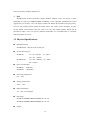
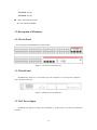
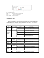
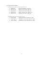
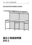
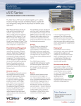
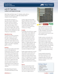
SS3GR50i / SS3GR26i L3 Gigabit Ethernet Switch With IP Stacking Installation Guide (v1.3) i Copyright © Amer.com Corp., 1997-2007 All rights reserved. No part of this publication may be reproduced in any form or by any means or used to make any derivative such as translation, transformation, or adaptation without permission from Amer.com, as stipulated by the United States Copyright Act of 1976. Amer.com reserves the right to make changes to this document and the products which it describes without notice. Amer.com shall not be liable for technical or editorial errors or omissions made herein; nor for incidental or consequential damages resulting from the furnishing, performance, or use of this material. Amer.com is a registered trademark of Amer.com. All other trademarks and trade names are properties of their owners. Contact Information Phone: 1-800-262-9703 [email protected] [email protected] ii Overview SS3GR50i/26i switch is a high performance route switch, that can be deployed as aggregation equipment for IP metropolitan area networks (MAN). SS3GR50i/26i switch can seamlessly support various network interfaces from 10Mb, 100Mb, 1000Mb to 10Gb Ethernets. We strongly recommend you to read through this manual carefully before installing and configuring to avoid possible damage to the switch and malfunction. iii FCC - Class A This equipment has been tested and found to comply with the limits for a Class A digital device, pursuant to part 15 of the FCC Rules. These limits are designed to provide reasonable protection against harmful interference when the equipment is operated in a commercial environment. This equipment generates, uses, and can radiate radio frequency energy and, if not installed and used in accordance with the instruction manual, may cause harmful interference to radio communications. Operation of this equipment in a residential area is likely to cause harmful interference in which case the user will be required to correct the interference at his own expense. You are cautioned that changes or modifications not expressly approved by the party responsible for compliance could void your authority to operate the equipment. You may use unshielded twisted-pair (UTP) for RJ-45 connections - Category 3 or better for 10 Mbps connections, Category 5 or better for 100 Mbps connections, Category 5, 5e, or 6 for 1000 Mbps connections. For fiber optic connections, you may use 50/125 or 62.5/ 125 micron multimode fiber or 9/125 micron single-mode fiber. iv Table of Contents Overview....................................................................................................................... iii Table of Contents ............................................................................................................ v Chapter 1 Introduction .................................................................................................1-1 1.1 PRODUCT BRIEF ................................................................................1-1 1.1.1 Overview................................................................................................ 1-1 1.1.2 Features and Benefits ............................................................................. 1-2 1.2 PHYSICAL SPECIFICATIONS ...................................................................1-3 1.3 DESCRIPTION OF HARDWARE ................................................................1-4 1.3.1 Front Panel............................................................................................. 1-4 1.3.2 Back Panel ............................................................................................. 1-4 1.3.3 DC Power Input ...................................................................................... 1-4 1.3.4 Status LEDs ............................................................................................ 1-5 Chapter 2 Hardware Installation ....................................................................................2-1 2.1 INSTALLATION NOTICE ........................................................................2-1 2.1.1 Environmental Requirements ................................................................... 2-1 2.1.2 Installation Notice ................................................................................... 2-4 2.1.3 Security Warnings ................................................................................... 2-4 2.2 INSTALLATION PREPARATION .................................................................2-4 2.2.1 Verify the Package Contents .................................................................... 2-4 2.2.2 Required Tools and Utilities...................................................................... 2-5 2.3 HARDWARE INSTALLATION....................................................................2-5 2.3.1 Installing the Switch................................................................................ 2-5 2.3.2 Connecting Console................................................................................. 2-6 2.3.3 SFP Transceiver Installation ..................................................................... 2-7 2.3.4 XFP Transceiver Installation ..................................................................... 2-7 2.3.5 Copper Cable/Fiber Cable Connection ....................................................... 2-8 2.3.6 Connecting Switches in a Stack ................................................................ 2-9 2.3.7 Power Supply Connection .......................................................................2-10 v Chapter 1 Introduction 1.1 Product Brief SS3GR50i/26i front panel: Figure 1-1 SS3GR50i and SS3GR26i Switch 1.1.1 Overview SS3GR50i/26i switch switch are 10Gb Ethernet routing switch. The switch has 48/24 fixed 1000Mb copper ports (44/20 1000Mb ports and 4 1000Mb COMBO ports) and 2 fixed 10Gb XFP ports and 2 fixed 10Gb stacking ports.SS3GR50i/26i switch switch are based on 10Gb switching technology. The switches fully support IPv6, whereas their height is only 1U. As distribution layer switches which are featured in high performance, small size and flexibility, SS3GR50i/26i switch switch with advanced intelligent and secure features, can serve ideally as distribution layer switches for campus networks, enterprise networks and IP metropolitan networks; as well as core layer switches for small and medium-sized networks. The rear panel provides two slots for single-port 10 Gigabit Ethernet hot-swappable expansion modules, and two stacking ports. Units can be stacked up to eight high through the built-in stacking ports that provide a 48 Gbps stack backplane. The switches include an SNMP-based management agent embedded on the main board, which supports both in-band and out-of-band access for managing the stack. These switches can easily tame your network with full support for Spanning Tree Protocol, Multicast Switching, Virtual LANs, and IP routing. It brings order to poorly performing networks by segregating them 1-1 into separate broadcast domains with IEEE 802.1Q compliant VLANs, empowers multimedia applications with multicast switching and CoS services, and eliminates conventional router bottlenecks. These switches can be used to augment or completely replace slow legacy routers, off-loading local IP traffic to release valuable resources for non-IP routing or WAN access. With wire-speed performance for Layer 2 and Layer 3, these switches can significantly improve the throughput between IP segments or VLANs. 1.1.2 Features and Benefits Various Interfaces The switch provides 44/20 fixed 1000Mb copper ports, 4 1000Mb COMBO ports (1000Mb fiber SFP ports/1000Mb copper ports) and 2 fixed 10Gb XFP ports and 2 stacking ports. Secure Power Supply The switch provides AC/DC power redundancy. It can be deployed with 220V AC power input, 12V DC power input or 220V AC power/12V DC power input simultaneously. Support 10Gb Ethernet 10Gb Ethernet which adopts full-duplex technology instead of low-speed, half-duplex CSMA/CD protocol, is a big leap in the evolution of Ethernet. 10Gb Ethernet can be deployed in star or ring topologies. With 10Gb Ethernet, SS3GR50i/26i switch switch provide broad bandwidth and powerful processing capacity. It is suitable for metropolitan networks and wide area networks. Using SS3GR50i/26i switch switch, users can simplify network structures and reduce cost of network construction. Networking Protocols SS3GR50i/26i switch switch support 802.1d/w/s, 802.1Q, 802.1p, 802.3ad, 802.3x, GVRP, DHCP and SNTP etc. The switches also support comprehensively the multicast protocols such as IGMP, DVMRP and PIM. Moreover, SS3GR50i/26i switch switch support RIPv1/2, OSPF and IPv6. All these protocols supported enable SS3GR50i/26i switch switch to meet the requirements of complex network constructions. ACL SS3GR50i/26i switch switch support comprehensively ACL policies. The traffic can be classified by source/destination IP addresses, source/destination MAC addresses, IP protocols, TCP/UDP, IP precedence, time ranges and ToS. And various policies can be conducted to forward the traffic. By implementing ACL policies, users can filter the virus packets such as “Worm.Blaster”, “Worm.Sasser” and “Red Code” etc. SS3GR50i/26i switch switch also support IEEE802.1x port based access authentication, which can be deployed with RADIUS, to ensure the 1-2 port level security and block illegal users. QoS SS3GR50i/26i switch switch fully support DiffServ Module. Users can specify a queue bandwidth on each port. WRR/SP/SWRR scheduling is also supported. SS3GR50i/26i switch supports the port security. Users can deploy trusted CoS, DSCP, IP precedence and port priority. User can also modify packets’ DSCP and COS values. The traffic can be classified by port, VLAN, DSCP, IP precedence and ACL table. User can also modify packets’ DSCP and IP precedence values. Users can specify different bandwidths for voice/data/video to customize different qualities of service. 1.2 Physical Specifications Management Port SS3GR50i/26i : 1 RJ-45 serial console port AC/DC Power Input SS3GR26i: AC: 90 ~ 264VAC,47 ~ 63Hz DC: -40 ~ -60VDC SS3GR50i/26i AC: 100 ~ 240VAC,50 ~ 60Hz DC: 12VDC Power Consumption SS3GR26i: 80W Max SS3GR50i: 120W Max Operating Temperature 0°C ~ 50°C Storage Temperature -40°C ~ 70°C Relative Humidity 5% ~ 95%, no condensate Dimension SS3GR26i: 440mm×44mm×410mm(W * H * D) SS3GR50i: 440mm×44mm×390mm(W * H * D) Weight 1-3 SS3GR50i: 6.1 kg SS3GR26i: 5.7 kg Mean Time Between Failure Min. 80, 000 Hours MTBF 1.3 Description of Hardware 1.3.1 Front Panel The front panel of SS3GR50i/26i is shown below: Figure 1-2 Front Panel of SS3GR50i/26i 1.3.2 Back Panel SS3GR50i/26i: There are 1x 110v/220v AC power receptacle, 1x12v DC power receptacle and 1x ground connection. Figure 1-3 Back Panel of SS3GR50i/26i 1.3.3 DC Power Input SS3GR50i/26i supports AC/DC power redundancy. -48 DC power’s pin-outs are distributed as below: 1-4 Figure 1-4 SS3GR50I DC Power Input Pin-outs Distribution DC power has 3 pin-outs: PIN1: V+ DC power positive electrode input PIN2: V- DC power cathode input PIN3: CGND Ground connection 1.3.4 Status LEDs SS3GR50i/26i includes a display panel and port indications that simplify installation and network troubleshooting. The LEDs, which are located on the front panel for easy viewing, are shown below and described in the following table. Table 1.1 LED Power Indicator Operation indicator SS3GR50i/26i LED Status Panel Symbol Status Description On (Green) Power is operating normally. Off Power is off. On (Green, blink at 1 Hz) System is operating normally. On (Green, blink at 8 Hz) System is loading. On (Red, blink at 8 Hz) System is malfunctioning. On (Green) RJ-45 port is connected. Off RJ-45 port is not connected. Blink (Green) Sending or receiving data On (Green) SFP transceiver is connected. Off SFP transceiver is not connected. Blink (Green) Sending or receiving data On (Green) XFP transceiver is connected. PWR RUN RJ-45 Port Indicator Status Indicator On the left Transfer Indicator On the right SFP Port Indicator Status Indicator On the left Transfer Indicator On the right XFP Port Indicator Status Link 1-5 Indicator Transfer Indicator Table 1.2 Act Off XFP transceiver is not connected. Blink (Green) Sending or receiving data SS3GR50i/26i LEDs LED Panel ymbol Status On/(yellow,blink) Link/Activity Power Diag RPC On/(Green,blink) Description Yellow means on 10/100M link, blink means activity Green means on 1000M link, blink means activity Off No activity Green Power ok Yellow Power failure Off No power or failure Green,blink Diag is on Green Diag successfully finished Yellow Diag result with failure in system Green Redundancy power on charge Yellow Redundancy power failure Off Redundancy power shut down Green LAN switch as Stack Master Yellow LAN switch as Stack Slave Yellow,blink System electing Master Off Stack off Green Normal status with uplink and downlink Green,blink Uplink failure Yellow,blink Downlink failure Off No stack link Green With expand module Green,blink Disable expand module Off No expand module Stack Master Stack Link Module Stack ID Stack ID 1-8 Master ID is 1, Slave ID is 2-8 Off Stack off 1-6 1.3.5 Front Panel Port Description SS3GR50i/26i switch support the following SFP transceivers: z MGBM-GSX Gigabit SFP MM 850nm, 500m (SX) z MGBS-GLX10 Gigabit SFP SM 1310nm, 10Km (LX) z MGBS-GLX20 Gigabit SFP SM 1310nm, 20Km (LX) z MGBS-GLX40 Gigabit z MGBS-GLX70 Gigabit SFP SM 1550nm, 70Km (ZX) SFP SM 1310nm, 40Km (LHX) SS3GR50i/26i supports the following XFP transceivers: z XFPM-10GSR 10GBASE-SR 850nm multimode XFP, 300m z XFPS-10GLR10 10GBASE-LR 1310nm single-mode XFP, 10KM z XFPS-10GER40 10GBASE-ER 1310nm single-mode XFP, 40KM 1-7 Chapter 2 Hardware Installation 2.1 Installation Notice To ensure the proper operation of SS3GR50i/26i switch and your physical security, please read carefully the following installation guide. 2.1.1 Environmental Requirements The switch must be installed in a clean area. Otherwise, the switch may be damaged by electrostatic adherence. Maintain the temperature within 0 to 50 °C and the humidity within 5% to 95%, non-condensing. The switch must be put in a dry and cool place. Leave sufficient spacing around the switch for good air circulation. The switch must work in the right range of power input (AC power: 90 ~ 264V (50Hz), DC power: -40 ~ -60V) The switch must be well grounded in order to avoid ESD damage and physical injury of people. The switch should avoid the sunlight perpendicular incidence. Keep the switch away from heat sources and strong electromagnetic interference sources. The switch must be mounted to a standard 19’’ rack or placed on a clean level desktop. 2.1.1.1 Dust and Particles Dust is harmful to the safe operation of SS3GR50i/26i switch. Dust can lead to electrostatic adherence, especially likely under low relative humidity, causing poor contact of metal connectors or contacts. Electrostatic adherence will result in not only reduced product lifespan, but also increased chance of communication failures. The recommended value for dust content and particle diameter in the site is shown below: Max Diameter (µm) Max Density (particles/m³) 0.5 1 3 5 1.4×10⁷ 7×10⁵ 2.4×10⁵ 1.3×10⁵ Table 2.1 Environmental Requirements: Dust In addition, salt, acid and sulfide in the air are also harmful to the switch. Such harmful gases will aggravate metal corrosion and the aging of some parts. The site should avoid harmful gases, such as SO2, H2S, NO2, NH3 and Cl2, etc. The table below details the threshold value. 2-1 Gas Average (mg/m³) Max (mg/m³) SO2 0.2 1.5 H2S 0.006 0.03 NO2 0.04 0.15 NH3 0.05 0.15 Cl2 0.01 0.3 Table 2.2 Environmental Requirements: Particles 2.1.1.2 Temperature and Humidity Although the switch is designed to use 4 fans, the site should still maintain a desirable temperature and humidity. High-humidity conditions can cause electrical resistance degradation or even electric leakage, degradation of mechanical properties and corrosion of internal components. Extreme low relative humidity may cause the insulation spacer to contract, making the fastening screw insecure. Furthermore, in dry environments, static electricity is liable to be produced and cause harm to internal circuits. Temperature extremes can cause reduced reliability and premature aging of insulation materials, thus reducing the switch’s working lifespan. In the hot summer, it is recommended to use air-conditioners to cool down the site. And the cold winter, it is recommenced to use heaters. The recommended temperature and humidity is shown below: Temperature: Relative humidity Long term condition Short term condition Long term condition Short term condition 15 ~ 30°C 0 ~ 50°C 40 ~ 65% 10 ~ 95% Table 2.3 Environmental Requirements: Temperature and Humidity Caution A sample of ambient temperature and humidity should be taken at 1.5m above the floor and 0.4m in front of the switch rack, with no protective panel covering the front and rear of the rack Short term working conditions refer to a maximum of 48 hours of continued operation and an annual cumulative total of less than 15 days. Formidable operation conditions refers to the ambient temperature and relative humidity value that may occur during an air-conditioning system failure, and normal operation conditions should be recovered within 5 hours. 2.1.1.3 Power Supply Before powering on the power supply, please check the power input to ensure proper grounding 2-2 of the power supply system. The input source for the switch should be reliable and secure, a voltage adaptor can be used if necessary. The building’s circuit protection system should include in the circuit a fuse or circuit-breaker of no greater than 240 V, 10 A. It is recommended to use a UPS for more reliable power supplying. . Caution Improper power supply system grounding, extreme fluctuation of the input source, and transients (or spikes) can result in larger error rate, or even hardware damage! 2.1.1.4 Preventing Electrostatic Discharge Damage Static electric discharges can cause damage to internal circuits, even the entire switch. Follow these guidelines for avoiding ESD damage: Ensure proper earth grounding of the device; Perform regular cleaning to reduce dust; Maintain proper temperature and humidity; Always wear an ESD wrist strap and antistatic uniform when in contact with circuit boards. 2.1.1.5 Anti-interference All sources of interference, whether from the device/system itself or the outside environment, will affect operations in various ways, such as capacitive coupling, inductive coupling, electromagnetic radiation, common impedance (including the grounding system) and cables/lines (power cables, signal lines, and output lines). The following should be noted: Precautions should be taken to prevent power source interruptions; Provide the system with a dedicated grounding, rather than sharing the grounding with the electronic equipment or lightning protection devices. Keep away from high power radio transmitters, radar transmitters, and high frequency strong circuit devices. Provide electromagnetic shielding if necessary. 2.1.1.6 Rack Configuration The dimensions of the SS3GR50i are designed to be mounted on a standard 19’’ rack, the dimensions are 440mm x 44mm x 410mm / 440mm x 44mm x 390mm (W x H x D). Please ensure good ventilation for the rack. Every device in the rack will generate heat during operation, therefore vent and fans must be provided for an enclosed rack, and devices should not be stacked closely. 2-3 When mounting devices in an open rack, care should be taken to prevent the rack frame from obstructing the switch ventilation openings. Be sure to check the positioning of the switch after installation to avoid the aforementioned. Caution If a standard 19’’ rack is not available, the SS3GR50i/26i can be placed on a clean level desktop, leave a clearance of 10mm around the switch for ventilation, and do not place anything on top of the switch. 2.1.2 Installation Notice Read through the installation instruction carefully before operating on the system. Make sure the installation materials and tools are prepared. And make sure the installation site is well prepared. During the installation, users must use the brackets and screws provided in the accessory kit. Users should use the proper tools to perform the installation. Users should always wear antistatic uniform and ESD wrist straps. Users should use standard cables and connecters. After the installation, users should clean the site. Before powering on the switch, users should ensure the switch is well grounded. Users should maintain the switch regularly to extend the lifespan of the switch. 2.1.3 Security Warnings When using SFP transceiver, do not stare directly at the fiber bore when the switch is in operation. Otherwise the laser may hurt your eyes. Do not attempt to conduct the operations which can damage the switch or which can cause physical injury. Do not install, move or disclose the switch and its modules when the switch is in operation. Do not open the switch shell. Do not drop metals into the switch. It can cause short-circuit. Do not touch the power plug and power socket. Do not place the tinder near the switch. Do not configure the switch alone in a dangerous situation, Use standard power sockets which have overload and leakage protection. Inspect and maintain the site and the switch regularly. Have the emergence power switch on the site. In case of emergence, switch off the power immediately. 2.2 Installation Preparation 2.2.1 Verify the Package Contents 2-4 Please unpack the shipping package and verify carefully the contents inside. SS3GR50i/26i switch should include the followings: ITEM No. Part name Number 1 SS3GR50i/26i switch 1 2 AC power cable 1 3 Manual CD 1 4 Console cable 1 5 Chassis bracket 2 6 Bracket screw 4 Figure 2.4 SS3GR50i/26i switch Packaging Contents Note: The above contents are subject to the received contents within the package. 2.2.2 Required Tools and Utilities The required tools and utilities are shown below: Philip/cross Screwdrivers Flat-blade screwdriver ESD wrist strap Antistatic uniform Caution Users should prepare the required tools and utilities by themselves. 2.3 Hardware Installation 2.3.1 Installing the Switch Please mount SS3GR50i/26i on the 19’’ rack as below: 1. Attach the 2 brackets on the SS3GR50i/26i switch with screws provided in the accessory kit. 2. Put the bracket-mounted switch smoothly into a standard 19’’ rack. Fasten the SS3GR50i/26i switch to the rack with the screws provided. Leave enough space around the switch for good air circulation. 2-5 Figure 2-1 Rack-mounting SS3GR50I Caution The brackets are used to fix the switch on the rack. They can’t serve as a bearing. Please place a rack shelf under the switch. Do not place anything on top of the switch. Do not block the blowholes on the switch to ensure the proper operation of the switch. 2.3.2 Connecting Console SS3GR50i/26i switch has a RJ45 console port, which can be connected with a RJ45 to DB9 serial cable (also comes with the device). Figure 2-2 Connecting Console to SS3GR50i/26i The connection procedure is listed below: 1. Find the console cable provided in the accessory kit. Attach the RJ-45 connector to the console port on the front panel. 2. Connect the other side of the console cable (DB9 female)to a character terminal (Admin PC). 3. Power on the switch and the character terminal. Configure the switch through the character terminal. 2-6 2.3.3 SFP Transceiver Installation An optional Gigabit SFP transceiver (1000BASE-SX, 1000BASE-LX or 1000BASE-LH) can be used for a backbone connection between switches, or for connecting to a high-speed server. Each single-mode fiber port requires 9/125 micron single-mode fiber optic cable with an LC connector at both ends. Each multimode fiber optic port requires 50/125 or 62.5/125 micron multimode fiber optic cabling with an LC connector at both ends. Caution: These switches use lasers to transmit signals over fiber optic cable. The lasers are compliant with the requirements of a Class 1 Laser Product and are inherently eye safe in normal operation. However, you should never look directly at a transmit port when it is powered on. Note: When selecting a fiber SFP device, considering safety, please make sure that it can function at a temperature that is not less than the recommended maximum operational temperature of the product. You must also use an approved Laser Class 1 SFP transceiver. Figure 2-3 Making Connections to SFP Transceivers 1. Remove and keep the LC port’s rubber cover. When not connected to a fiber cable, the rubber cover should be replaced to protect the optics. 2. Check that the fiber terminators are clean. You can clean the cable plugs by wiping them gently with a clean tissue or cotton ball moistened with a little ethanol. Dirty fiber terminators on fiber cables will impair the quality of the light transmitted through the cable and lead to degraded performance on the port. 3. Connect one end of the cable to the LC port on the switch and the other end to the LC port on the other device. Since LC connectors are keyed, the cable can be attached in only one orientation. 4. As a connection is made, check the Link LED on the switch corresponding to the port to be sure that the connection is valid. The 1000BASE-SX, 1000BASE-LX and 1000BASE-LH fiber optic ports operate at 1 Gbps full duplex. 2.3.4 XFP Transceiver Installation 2-7 The switch has 2 10Gb fiber transceiver slots. The procedure for installing the XFP 10Gb fiber transceiver is shown below: Step 1: Put on an ESD wrist strap (or antistatic gloves) Step 2: Insert the XFP transceiver to the guide rail inside the 10Gb line card. Do not to put the XFP transceiver up-side-down. Step 3: Push the XFP transceiver along the guide rail gently until it comes into contact with the front panel of the 10Gb line card. Note: The XFP 10Gb transceiver is hot swappable. Caution Do not look at the 2 fiber bore in the XFP transceiver when the switch is in operation, otherwise the laser may hurt your eyes. 2.3.5 Copper Cable/Fiber Cable Connection Copper cables should be connected as below: Step 1: Insert one end of the Ethernet cable to the RJ-45 Ethernet port in the switch copper cable line card; Step 2: Insert the other end of the Ethernet cable to the RJ-45 Ethernet port of some other device; Step 3: Check all status indicators for the corresponding ports; a lighted LED indicates that the link has been established, otherwise the link is not ready and the cable should be examined. Caution Please verify the sign above the port to ensure using the right port. Connecting to wrong ports might damage the switch. Fiber cables should be connected as below: Step 1: remove the protective plug from the SFP/XFP fiber transceiver bore; Remove the protective cap from one end of the fiber cable. Keep the fiber end clean and neat. Step 2: Attach one end of the fiber cable to the SFP/XFP transceiver, and attach the other end to the transceiver of the corresponding devices. Note: The SFP/XFP transceiver’s TX port should be connected to the RX port of the corresponding device, and vice versa. Step 3: Check the fiber port status indicator, a lighted LED indicates that the link has been established; otherwise the link is not ready and should be examined. Caution Please verify the sign above the port to ensure using the other ports. Connecting to wrong ports might damage the transceiver or the other ports. When connecting other devices through a fiber cable to the switch, the output power of the fiber cable must not exceed the maximum received power of the corresponding modules. Otherwise, it will damage the switch. Do not stare at the fiber bore when the switch is in operation. That may hurt your eyes. 2-8 2.3.6 Connecting Switches in a Stack Figure 2-4 shows how the stack cables are connected between switches in a stack. Each stacking connection is a 48 Gbps full-duplex high-speed serial link using proprietary stacking cables. The switch supports a line and ring-topology stacking configuration, or can be used stand alone. To ensure minimal disruption in case a unit or stacking cable fails, we recommend always use a ring-topology. In line-topology stacking there is a single stack cable connection between each switch that carries two-way communications across the stack. In ring-topology stacking, an extra cable is connected between the top and bottom switches forming a “ring” or “closed-loop.” The closed-loop cable provides a redundant path for the stack link, so if one link fails, stack communications can still be maintained. Caution To avoid the flood traffic caused by the loop connection, either spanning tree or MRPP needs to be enabled and configured properly. Figure 2-4 illustrates a ring-topology stacking configuration. Figure 2-4 Making Stacking Connections To connect up to eight switches in a stack, perform the following steps: 1. Plug one end of the stack cable (ordered separately) in the Down (right) port of the top unit. 2. Plug the other end of the stack cable into the Up (left) port of the next unit. 2-9 3. Repeat steps 1 and 2 for each unit in the stack. Form a simple chain starting at the Down port on the top unit and ending at the Up port on the bottom unit (stacking up to 8 units). 4. (Optional) To form a wrap-around topology, plug one end of a stack cable into the Down port on the bottom unit and the other end into the Up port on the top unit. Stacking Topologies All units in the stack must be connected via stacking cable. You can connect units in a simple cascade configuration, connecting Down ports to Up ports, from the top unit to the bottom unit. Using this “line” topology, if any link or unit in the stack fails, the stack is split and two separate segments are formed. The Stack Link LEDs on the units that are disconnected flash to indicate that the stack link between them is not functioning (see Table 1-3 “System Status LEDs” on page 1-7). When using line topology and a stack link failure occurs, the stack reboots and a Master unit is selected within each of the two stack segments. The Master unit will be either the unit with the Master button depressed or the unit with the lowest MAC address if the Master button is not depressed on any unit. When the stack reboots and resumes operations, note that the IP address will be the same for both of the stack segments. To resolve the conflicting IP addresses, you should manually replace the failed link or unit as soon as possible. If you are using a wrap-around stack topology, a single point of failure in the stack will not cause the stack to fail. It would take two or more points of failure to break the stack apart. If the Master unit fails or is powered off, the backup unit will take control of the stack without any loss of configuration settings. The Slave unit with the lowest MAC address is selected as the backup unit. 2.3.7 Power Supply Connection SS3GR50i/26i switch uses 110v/220v AC power supply by default. Please read the power input specification for the detailed information. -48V(12V) DC power supply and AC/DC redundancy power input are also supported. Figure 2-5 Attaching power cable to SS3GR50i/26i switch 2-10 1. Insert one end of the power cable provided in the accessory kit into the power source socket (with overload and leakage protection), and the other end to the power socket in the back panel of the switch. 2. Check the power status indicator in the front panel of the switch. The corresponding power indicator should light. SS3GR50i/26i switch is self-adjustable for the input voltage. As soon as the input voltage is in the range printed on the switch surface, the switch can operate correctly. 3. When the switch is powered on, it executes self-test procedure and startups. Caution The input voltage must be within the required range, otherwise the switch can be damaged or malfunction. Do not open the switch shell without permission. It can cause physical injury. ©Amer.com Corp. 1997-2007 All rights reserved. 2-11