1
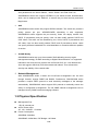
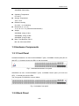
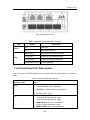
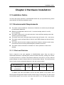
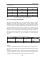
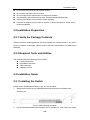
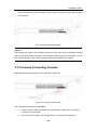
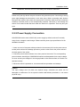
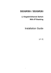
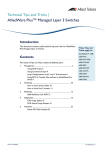
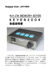
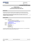
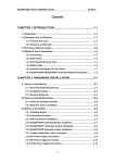
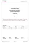
SS2GR50i / SS2GR26ip / SS2GR26i L2/L4 Managed Gigabit Ethernet Switch With IP Stacking and PoE Support Installation Guide Version 1.1 I Copyright © Amer.com Corp., 1997-2007 All rights reserved. No part of this publication may be reproduced in any form or by any means or used to make any derivative such as translation, transformation, or adaptation without permission from Amer.com, as stipulated by the United States Copyright Act of 1976. Amer.com reserves the right to make changes to this document and the products which it describes without notice. Amer.com shall not be liable for technical or editorial errors or omissions made herein; nor for incidental or consequential damages resulting from the furnishing, performance, or use of this material. Amer.com is a registered trademark of Amer.com. All other trademarks and trade names are properties of their owners. Contact Information Phone: 1-800-262-9703 [email protected] [email protected] II FCC - Class A This equipment has been tested and found to comply with the limits for a Class A digital device, pursuant to part 15 of the FCC Rules. These limits are designed to provide reasonable protection against harmful interference when the equipment is operated in a commercial environment. This equipment generates, uses, and can radiate radio frequency energy and, if not installed and used in accordance with the instruction manual, may cause harmful interference to radio communications. Operation of this equipment in a residential area is likely to cause harmful interference in which case the user will be required to correct the interference at his own expense. You are cautioned that changes or modifications not expressly approved by the party responsible for compliance could void your authority to operate the equipment. You may use unshielded twisted-pair (UTP) for RJ-45 connections - Category 3 or better for 10 Mbps connections, Category 5 or better for 100 Mbps connections, Category 5, 5e, or 6 for 1000 Mbps connections. For fiber optic connections, you may use 50/125 or 62.5/ 125 micron multimode fiber or 9/125 micron single-mode fiber. III Contents Chapter 1 Introduction ..............................................................1-1 1.1 Product Brief ...................................................................................1-1 1.1.1 Overview................................................................................................ 1-1 1.1.2 Features and Benefits .......................................................................... 1-1 1.2 Physical Specification....................................................................1-2 1.3 Hardware Components...................................................................1-3 1.3.1 Front Panel ............................................................................................ 1-3 1.3.2 Back Panel............................................................................................. 1-3 1.3.3 LED Explanation ................................................................................... 1-4 1.3.3.1 Port LEDs .................................................................................... 1-4 1.3.3.2 Status LEDs................................................................................. 1-6 1.3.4 Front Panel Port Description ............................................................... 1-7 Chapter 2 Hardware Installation...............................................2-1 2.1 Installation Notice...........................................................................2-1 2.1.1 Environmental Requirements .............................................................. 2-1 2.1.1.1 Dust and Particles ...................................................................... 2-1 2.1.1.2 Temperature and Humidity......................................................... 2-2 2.1.1.3 Power Supply .............................................................................. 2-3 2.1.1.4 Preventing Electrostatic Discharge Damage............................ 2-3 2.1.1.5 Anti-interference ......................................................................... 2-3 2.1.1.6 Rack Configuration..................................................................... 2-4 2.1.2 Installation Notice ................................................................................. 2-4 2.1.3 Security Warnings ................................................................................ 2-4 2.2 Installation Preparation ..................................................................2-5 2.2.1 Verify the Package Contents................................................................ 2-5 2.2.2 Required Tools and Utilities................................................................. 2-5 2.3 Installation Guide............................................................................2-5 2.3.1 Installing the Switch ............................................................................. 2-5 2.3.2 Console Connecting Console .............................................................. 2-6 2.3.3 SFP Transceiver Installation ................................................................ 2-7 2.3.4 Copper Cable/Fiber Cable Connection ............................................... 2-7 2.3.5 Power Supply Connection ................................................................... 2-8 IV Installation Guide Chapter 1 Introduction 1.1 Product Brief 1.1.1 Overview SS2GR50i/26i series switches from Amer.com, are fully featured Gigabit Layer 2/4 switches, are ideally used for deployment both at the core and the network edge to provide full gigabit connections throughout the network. SS2GR50i provides 44 gigabit copper ports and 4 dual-interface RJ45 / miniGBIC ports. SS2GR26i series comes with 22 gigabit copper ports ( SS2GR26IP supports PoE), and 4 dual-interface RJ45/miniGBIC combo ports provide flexibility between copper and fiber media. Comprehensive QoS, feature rich VLAN functions (Voice VLAN, Q in Q, VLAN VPN, etc), enhanced security, classified bandwidth control, link aggregation, this switch has all of the features you could ask for, and is also easy to configure and manage through single IP stacking (up to 24 units, also work with layer 3 10G switches from Amer.com) and industrial standard CLI shell and Web GUI. 1.1.2 Features and Benefits Flexible interface type SS2GR50i/26i series switch has several fixed 10/100/1000Base-T ports, and provides COMBO port as SFP form, the abundant port is convenient for networking demand. Networking Protocols SS2GR50I/26I/26IP supply 802.1d/w/s STP,and can support 802.1Q,802.1p, 802.3ad,802.3x,GVRP,DHCP,SNTP standards and so on. ACL SS2GR50i/26i series switch support comprehensively ACL policies. The traffic can be classified by source/destination IP addresses, source/destination MAC addresses, IP protocols, TCP/UDP, IP precedence, time ranges and ToS. And various policies can be conducted to forward the traffic. By implementing ACL policies, users can filter the 1-1 Installation Guide virus packets such as “Worm. Blaster”, “Worm. Sasser ”and “Red Code” etc. SS2GR50i/26i series also support IEEE802.1x port based access authentication, which can be deployed with RADIUS, to ensure the port level security and block illegal users. QoS SS2GR50i/26i series switch fully support DiffServ Module. The switch can provide 8 priority queues per port. WRR/SP/SWRR scheduling is also supported. SS2GR50i/26i series supports the port security. Users can deploy trusted CoS, DSCP, IP precedence and port priority. User can also modify packets’ DSCP and COS values. The traffic can be classified by port, VLAN, DSCP, IP precedence and ACL table. User can also modify packets’ DSCP and IP precedence values. Users can specify different bandwidths for voice/data/video to customize different qualities of service. 3D-SMP Ready SS2GR50i/26i series are up to the mustard of Self-defending security region management strategy 3D-SMP according to Digital China Networks. It is supported interaction with some security system such as firewall, IDS, etc. It can defense the virus and aggress effectively from the extranet and internet. Thus enhance the security and stability of the network-wide. Network Management With SS2GR50i/26i series, in-band and out-of-band management can be done through Console, support SNMP and RMON. Furthermore, SS2GR50i/26i series provides a unique SMTP protocol to send sensitivity messages to the manager automatically. SS2GR50i/26i series support SSH protocol to maximally ensure the safety of configuration management. The full SNMP network management can be managed via any SNMP network managing software. 1.2 Physical Specification Management Port 1 RJ-45 console port AC/DC Power Input AC: 100 ~ 240VAC,50~60Hz Power Consumption SS2GR26I: 50W Max SS2GR26IP: 225W Max, PoE Budget: 195 Watts 1-2 Installation Guide SS2GR50I: 58.4W Max Operating Temperature 0°C~50°C Storage Temperature -40°C~70°C Relative Humidity 5%~95%,no condensing Dimension (W x H x D) 17.3 x 16.3 x 1.7 in (440mmx44mmx229mm) Weight SS2GR26i: 4.2kg / 9.3lbs SS2GR26ip: 4.5kg / 9.9lbs SS2GR50i: 5.1kg/11.2lbs Mean Time Between Failure Min. 80, 000 Hours MTBF 1.3 Hardware Components 1.3.1 Front Panel SS2GR26I/SS2GR26IP has 22x10/100/1000Base-T ports, 4x1000Mb Combo ports (RJ-45 and SFP), 1 Console port and 32 LED’s on the front panel Fig 1-1 SS2GR26I/SS2GR26IP front panel SS2GR50I has 46x 10/100/1000Base-T ports, 4x1000Mb Combo ports (4 RJ-45 and SFP), 1 Console port and 56 LEDs. The front panel of SS2GR50I is shown below: Fig 1-2 SS2GR50I front panel 1.3.2 Back Panel 1-3 Installation Guide There is one 110~230V AC power supply plug on the back panel of the SS2GR50i/ SS2GR26i series. Fig 1-3 SS2GR50i / SS2GR26i back panel 1.3.3 LED Explanation The front panel LED of SS2GR50i/SS2GR26i series switch has two types of port LED and status LED, the explanation is shown as below: 1.3.3.1 Port LEDs Fig 1-4 SS2GR26I/SS2GR26IP LED Table1.1 SS2GR26I/SS2GR26IP port LEDs description 1-4 Installation Guide Panel Symbol Status On (yellow) Blink (yellow) Port1-24(Link/Act) On (Green) Blink (Green) Port21/22/23/24 Port is linked as 10Mbps or 100Mbps Port is linked as 10Mbps or 100Mbps and receives/sends data Port is linked as 1000Mbps Port is linked as 1000Mbps and receives/sends data Off Port linked failure On (Green) SFP module is exactly inserted Off SFP module is not inserted On (yellow) Port is linked as 10Mbps or 100Mbps Blink (yellow) Port25/26 Description On (Green) Blink (Green) Off Port is linked as 10Mbps or 100Mbps and receives/sends data Port is linked as 1000Mbps Port is linked as 1000Mbps and receives/sends data Port linked failure 1-5 Installation Guide Fig 1-5 SS2GR50i LED Table1.2 SS2GR50I port LED description Panel Symbol Status On (yellow) Blink (yellow) Port1-48(Link/Act) Port45/46/47/48 Description Port is linked as 10Mbps or 100Mbps Port is linked as 10Mbps or 100Mbps and receives/sends data On (Green) Port is linked as 1000Mbps Blink (Green) Port is linked as 1000Mbps and receives/sends data Off Port linked failure On (Green) SFP module is exactly inserted Off SFP module is not inserted On (yellow) Port is linked as 10Mbps or 100Mbps Blink (yellow) Port49/50 Port is linked as 10Mbps or 100Mbps and receives/sends data On (Green) Port is linked as 1000Mbps Blink (Green) Port is linked as 1000Mbps and receives/sends data Off Port linked failure 1.3.3.2 Status LEDs 1-6 Installation Guide Fig 1-6 SS2GR26IP LED Table1.3 SS2GR50i/26i series LED description LED Power Diag Status Description On Power ok Off No power or failure Blink (Yellow) Diag result with failure in system On (Green) Diagnosis successfully finished On (Yellow) System is initializing diagnosis Blink(Yellow, Green) Boot is initializing 1.3.4 Front Panel Port Description The front ports of SS2GR50I/26I series, are shown below and described in the following table. Table 1-4 Switch interface description Interface mode Spec RJ-45 z 10/100/1000Mbps auto negotiation z MDI/MDI-X cable mode auto negotiation z 5 kinds of UTP: 100 m z MGBM-GSX, SFP-SX-L transceiver 62.5/125um multimode fiber: 275m 50.0/125um multimode fiber: 550m z MGBS-GLX10, SFP-LX-L transceiver: 9/125um single mode fiber: 10km z MGBS-GLX40, SFP-LX-40 transceiver: SFP 1-7 Installation Guide 9/125um single mode fiber: 40km z MGBS-GLX70, SFP-LH-70-L transceiver: 9/125um single mode fiber: 70km z MGBS-GLX120, SFP-LH-120-L transceiver: 9/125um single mode fiber: 120km 1-8 Installation Guide Chapter 2 Hardware Installation 2.1 Installation Notice To ensure the proper operation of SS2GR50i/26i series and your physical security, please read carefully the following installation guide. 2.1.1 Environmental Requirements The switch must be installed in a clean area. Otherwise, the switch may be damaged by electrostatic adherence. Maintain the temperature within 0 to 50 °C and the humidity within 5% to 95%, non-condensing. The switch must be put in a dry and cool place. Leave sufficient spacing around the switch for good air circulation. The switch must work in the right range of power input (AC power: 100 ~ 240V (50Hz). The switch must be well grounded in order to avoid ESD damage and physical injury of person. The switch should avoid the sunlight perpendicular incidence. Keep the switch away from heat sources and strong electromagnetic interference sources. The switch must be mounted to a standard 19’’ rack or placed on a clean level desktop. 2.1.1.1 Dust and Particles Dust is harmful to the safe operation of SS2GR50i/26i series. Dust can lead to electrostatic adherence, especially likely under low relative humidity, causing poor contact of metal connectors or contacts. Electrostatic adherence will result in not only reduced product lifespan, but also increased chance of communication failures. The recommended value for dust content and particle diameter in the site is shown below: Max Diameter (µm) Max Density (particles/m³) 0.5 1 3 5 1.4×10⁷ 7×10⁵ 2.4×10⁵ 1.3×10⁵ Table 2.1 Environmental Requirements: Dust In addition, salt, acid and sulfide in the air are also harmful to the switch. Such harmful gases will aggravate metal corrosion and the aging of some parts. The site should avoid harmful gases, such as SO2, H2S, NO2, NH3 and Cl2, etc. The table below details 2-1 Installation Guide the threshold value. Gas Average (mg/m³) Max (mg/m³) SO2 0.2 1.5 H2S 0.006 0.03 NO2 0.04 0.15 NH3 0.05 0.15 Cl2 0.01 0.3 Table 2.2 Environmental Requirements: Particles 2.1.1.2 Temperature and Humidity Although the switch is designed to use 4 fans, the site should still maintain a desirable temperature and humidity. High-humidity conditions can cause electrical resistance degradation or even electric leakage, degradation of mechanical properties and corrosion of internal components. Extreme low relative humidity may cause the insulation spacer to contract, making the fastening screw insecure. Furthermore, in dry environments, static electricity is liable to be produced and cause harm to internal circuits. Temperature extremes can cause reduced reliability and premature aging of insulation materials, thus reducing the switch’s working lifespan. In the hot summer, it is recommended to use air-conditioners to cool down the site. And the cold winter, it is recommenced to use heaters. The recommended temperature and humidity is shown below: Temperature: Long term condition Relative humidity Short term condition Long term condition Short term condition 15 ~ 30°C 0 ~ 50°C 40 ~ 65% 10 ~ 95% Table 2.3 Environmental Requirements: Temperature and Humidity Caution A sample of ambient temperature and humidity should be taken at 1.5m above the floor and 0.4m in front of the switch rack, with no protective panel covering the front and rear of the rack. Short term working conditions refer to a maximum of 48 hours of continued operation and an annual cumulative total of less than 15 days. Formidable operation conditions refers to the ambient temperature and relative humidity value that may occur during an 2-2 Installation Guide air-conditioning system failure, and normal operation conditions should be recovered within 5 hours. 2.1.1.3 Power Supply The power input parameters for the switch is shown as below: AC input: 100~240VAC Frequency: 50~60H Before powering on the power supply, please check the power input to ensure proper grounding of the power supply system. The input source for the switch should be reliable and secure; a voltage adaptor can be used if necessary. The building’s circuit protection system should include in the circuit a fuse or circuit-breaker of no greater than 240V, 10A. It is recommended to use a UPS for more reliable power supplying. Caution Improper power supply system grounding, extreme fluctuation of the input source, and transients (or spikes) can result in larger error rate, or even hardware damage! 2.1.1.4 Preventing Electrostatic Discharge Damage Static electric discharges can cause damage to internal circuits, even the entire switch. Follow these guidelines for avoiding ESD damage: z Ensure proper earth grounding of the device; z Perform regular cleaning to reduce dust; z Maintain proper temperature and humidity; z Always wear an ESD wrist strap and antistatic uniform when dealing with circuit boards. 2.1.1.5 Anti-interference All sources of interference, whether from the device/system itself or the outside environment, will affect operations in various ways, such as capacitive coupling, inductive coupling, electromagnetic radiation, common impedance (including the grounding system) and cables/lines (power cables, signal lines, and output lines). The following should be noted: Precautions should be taken to prevent power source interruptions; Provide the system with a dedicated grounding, rather than sharing the grounding with the electronic equipment or lightning protection devices. Keep away from high power radio transmitters, radar transmitters, and high frequency strong circuit devices. 2-3 Installation Guide Provide electromagnetic shielding if necessary. 2.1.1.6 Rack Configuration The dimensions of the switch are designed to be mounted on a standard 19’’ rack, the dimensions are 440mm x 44mm x 410mm (W x H x D). Please ensure good ventilation for the rack. Every device in the rack will generate heat during operation, therefore vent and fans must be provided for an enclosed rack, and devices should not be stacked closely. When mounting devices in an open rack, care should be taken to prevent the rack frame from obstructing the switch ventilation openings. Be sure to check the positioning of the switch after installation to avoid the aforementioned. Caution If a standard 19’’ rack is not available, the switch can be placed on a clean level desktop, leave a clearance of 10mm around the switch for ventilation, and do not place anything on top of the switch. 2.1.2 Installation Notice Read through the installation instruction carefully before operating on the system. Make sure the installation materials and tools are prepared. And make sure the installation site is well prepared. During the installation, users must use the brackets and screws provided in the accessory kit. Users should use the proper tools to perform the installation. Users should always wear antistatic uniform and ESD wrist straps. Users should use standard cables and connecters. After the installation, users should clean the site. Before powering on the switch, users should ensure the switch is well grounded. Users should maintain the switch regularly to extend the lifespan of the switch. 2.1.3 Security Warnings When using SFP transceiver, do not stare directly at the fiber bore when the switch is in operation. Otherwise the laser may hurt your eyes. Do not attempt to conduct the operations which can damage the switch or which can cause physical injury. Do not install, move or disclose the switch and its modules when the switch is in operation. Do not open the switch shell. Do not drop metals into the switch. 2-4 Installation Guide Do not touch the power plug and power socket. Do not place the tinder near the switch. Do not configure the switch alone in a dangerous situation, Use standard power sockets which have overload and leakage protection. Inspect and maintain the site and the switch regularly. Have the emergence power switch on the site. In case of emergence, switch off the power immediately. 2.2 Installation Preparation 2.2.1 Verify the Package Contents Please unpack the shipping package and verify carefully the contents inside. If any stuff in the box is absent or damaged, please connect with the local distributor or Digital China Networks. 2.2.2 Required Tools and Utilities The required tools and utilities are shown below: Cross screwdrivers Flat-blade screwdriver ESD wrist strap Antistatic uniform 2.3 Installation Guide 2.3.1 Installing the Switch Please mount SS2GR50i/26i series on the 19’’ rack as below. 1. Attach the 2 brackets on the SS2GR50i/26i series with screws provided in the accessory kit. Fig 2-1 Rack-mounting the switch 2. Put the bracket-mounted switch smoothly into a standard 19’’ rack. Fasten the switch 2-5 Installation Guide to the rack with the screws provided. Leave enough space around the switch for good air circulation. Fig 2-2 Rack-mounting the switch Caution The brackets are used to fix the switch on the rack. They can’t serve as a bearing. Please place a rack shelf under the switch. Do not place anything on top of the switch. Do not block the blowholes on the switch to ensure the proper operation of the switch. 2.3.2 Console Connecting Console SS2GR50i/26i series provides a RJ-45 interface console port. Fig 2-3 Connecting Console cable The connection procedure is listed below 1. Find the console cable provided in the accessory kit. Attach the RJ-45 end to console port of the switch. 2. Connect the other side of the console cable to a character terminal (PC). 2-6 Installation Guide 3. Power on the switch and the character terminal. Configure the switch through the character terminal. 2.3.3 SFP Transceiver Installation SS2GR50i/26i series provides multiple 1000Mb SFP transceiver slots. The procedure for installing the SFP transceiver is shown below: Step 1: Put on a ESD wrist strap (or antistatic gloves) Step 2: Insert the SFP transceiver to the guide rail inside the fiber interface line card. Do not put the SFP transceiver up-side-down. Step 3: Push the SFP transceiver along the guide rail gently until you feel the transceiver snap into place at the bottom of the line card. Note: the SFP transceiver is hot swappable. Caution Do not stare directly into the 2 fiber bore in the SFP transceiver when the switch is in operation, otherwise the laser may cause serious damages to your eyes. 2.3.4 Copper Cable/Fiber Cable Connection Copper cables should be connected as below: Step 1: Insert one end of the Ethernet cable to the RJ-45 Ethernet port in the switch copper cable line card; Step 2: Insert the other end of the Ethernet cable to the RJ-45 Ethernet port of some other device; Step 3: Check all status indicators for the corresponding ports; a lighted LED indicates that the link has been established, otherwise the link is not ready and the cable should be examined. Caution! Please verify the sign above the port to ensure using the right port. Connecting to wrong ports might damage the switch. Fiber cables should be connected as below: Step 1: Remove the protective plug from the SFP/XFP fiber transceiver bore; Remove the protective cap from one end of the fiber cable. Keep the fiber end clean and neat. Step 2: Attach one end of the fiber cable to the SFP/XFP transceiver, and attach the other end to the transceiver of the corresponding devices. Note: The SFP/XFP transceiver’s TX port should be connected to the RX port of the corresponding device, and vice versa. Step 3: Check the fiber port status indicator, a lighted LED indicates that the link has been 2-7 Installation Guide established; otherwise the link is not ready and should be examined. Caution Please verify the sign above the port to ensure using the other ports. Connecting to wrong ports might damage the transceiver or the other ports. When connecting other devices through a fiber cable to the switch, the output power of the fiber cable must not exceed the maximum received power of the corresponding modules. Otherwise, it will damage the switch. Do not stare at the fiber bore when the switch is in operation. That may hurt your eyes. 2.3.5 Power Supply Connection SS2GR50i/26i series uses110/220V AC power supply by default, and can fit a totally range for the voltage’s small change. Please read the power input specification for the detailed information. 1. Insert one end of the power cable provided in the accessory kit into the power source socket (with overload and leakage protection), and the other end to the power socket in the back panel of the switch. 2. Check the power status indicator in the front panel of the switch. The corresponding power indicator should light. SS2GR50i/26i series is self-adjustable for the input voltage. As soon as the input voltage is in the range printed on the switch surface, the switch can operate correctly. 3. When the switch is powered on, it executes self-test procedure and startups. Caution The input voltage must be within the required range, otherwise the switch can be damaged or malfunction. Do not open the switch shell without permission. It can cause physical injury. 2-8 Installation Guide ©Amer.com Corp. 1997-2007 All rights reserved. 2-9