1
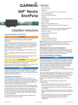
Network Interface Card
User's Guide
Version 1.2
P/N: ATC111-9904 Rev.A
This User's Guide contains important
information regarding the installation of your
network adapter card. Please read it completely
before attempting to install your Network
Interface Card.
For future reference, record the serial number of
your network adapter in the space below:
SERIAL Number
The serial number is located on the front of the card.
Amer.com
7259 Bryan Dairy Road, Largo, Florida 33777.
© Amer.com, 1997-1999. All rights reserved. No part of this
publication may be reproduced in any form or by any means or used to
make any derivative such as translation, transformation, or adaptation
without permission from Amer.com, as stipulated by the United States
Copyright Act of 1976.
Amer.com reserves the right to make changes to this document and
the products which it describes without notice. Amer.com shall not be
liable for technical or editorial errors or omissions made herein; nor for
incidental or consequential damages resulting from the furnishing,
performance, or use of this material.
United States Government Legends:
If you are a United States government agency, then this publication
and the software described herein are provided subject to the following
restricted rights:
For units of the Department of Defense:
Restricted Rights Legend: Use, duplication or disclosure by the
Government is subject to restrictions as set forth in subparagraph(c)
(1) (ii) for Restricted Rights in technical Data and Computer Software
clause at 48 C.F.R. 52.227-7013.
For civilian agencies:
Restricted Rights Legend: Use, reproduction or disclosure is subject to
restrictions set forth in subparagraph (a) through (d) of the Commercial
Computer Software - Restricted Rights Clause at 48 C.F.R. 52.227-19
and the limitations set forth in Amer.com’s standard commercial
agreement for the software. Unpublished rights reserved under the
copyright laws of the United States.
Amer.com is a registered trademark of Amer.com. All other
trademarks and trade names are properties of their owners.
1
Getting Started
This manual discusses three Network Interface Cards. The model
numbers C1, C10s, and C110w are part of the Amer.com family of
desktop Personal Computer(PC) network adapters. The information
provided in this manual is applicable to all three adapters, and at
particular points, the differentiating elements between them will be
mentioned.
The C1 and C10s Network Interface Cards are designed for 10Mbps
Ethernet. Both cards have one thin coax(BNC) and one TwistedPair(RJ-45) port. The C1 supports ISA bus computers while the C10s
supports PCI bus computers.
The C110w Network Interface Card is designed for 10 or 100Mbps
transfer speeds. It has one auto-detecting Twisted-Pair(RJ-45) port that
supports both 10Base-T Ethernet and 100Base-TX Fast Ethernet.
C110w
C10s
C1
Backplates
and their
connectors
RJ-45
connector
BNC
connector
Type of
cabling
PC Bus
Architecture
10BASE-T
or 100BASE-TX
Auto-detect
10BASE-T
or Thin coax
10BASE-T
or Thin coax
PCI
32bit
PCI
32bit
ISA
16bit
Before you install the C1 or C10s hardware, confirm the type of adapter
you have -- that it matches your PC’s bus architecture -- and decide
whether you'll use thin coax or Twisted-Pair(10BaseT) cable. For the
PCI compliant C110w, the adapter will auto-detect (10Mbps or
100Mbps) the network connection using 10/100NWay auto-negotiation
when connected to the Twisted-Pair cable. If connecting directly to a
switching device rather than a shared hub, the card will also adjust
duplex mode (half-duplex, being one-way-at-a-time, or full duplex, being
simultaneous transmit-and-receive).
2
Thin coax cabling looks similar to the copper coaxial cable that is often
used to connect a VCR to a TV set. Twisted-Pair cabling resembles
ordinary telephone cables. The difference between network cable and
telephone cable is that network complies to higher standards of
telecommunication approval, except that it has between 6 and 8 wires
inside instead of 4, and they're usually twisted every 2 inches (5 cm)
together inside to help reduce interference.
Thin coax cabling is often used to create a network "backbone" of
computers. PCs are chained together in a long line. A cable goes
from the first PC to the second; a second cable goes from the second
PC to the third, and so forth to a maximum of 30 computers per line.
No matter how many computers are connected together, thin coax
always requires termination at both ends of the network, which is the
act of "plugging up" the network so that no information is damaged and
becomes discarded. Instead of inserting an incoming coax (also
known as 10Base-2) cable directly into each PC's network card, a Tconnector is placed on the back of the adapter (Diag. Pg. 7) instead,
splitting the network card's input port into two separate ports. One port
receives an incoming network cable; the other
receives an outgoing network cable.
If the PC is at the end
of the network chain,
a terminator plug is
inserted into the empty
leg of the T-connector.
Twisted-Pair cabling is great for small offices with walls, partitions, or
modular situations where computers may be moved around. TwistedPair cable cannot be used to connect PCs together without the use of
a hub. A hub is a central wiring device with RJ-45 ports. Each PC has
its own twisted-pair cable that connects its network card to the hub.
Because all of the cables from the PCs converge and terminate at the
hub's central location, a Twisted-Pair
network is often referred to as a star
configuration (compare this to
thin coax's backbone
configuration sometimes
referred to as a bus
configuration).
3
Hubs, cards, and twisted-pair cables are available directly from
Amer.com. Be sure to measure the distance between your PCs to
determine how much cable you'll need. The maximum distance for a
thin coax backbone is 607 feet (185 meters); the maximum for a strand
of Twisted-Pair cable is 328 feet (100 meters).
If you use thin coax cabling, you'll need:
1 Network Interface Card for each computer
1 thin coax cable for each PC-to-PC connection
1 T-connector for each PC
2 50-ohm terminator plugs (one for each end of the network)
!
!
!
!
If you use Twisted Pair, you'll need:
1 Network Interface Card for each computer
1 Hub with enough ports to support all of your PCs (you may
need more than 1 hub)
1 Twisted-Pair Cable for each PC
!
!
!
Installing the Network Interface Card
Installation of the Network Adapter requires 2 steps. (1)Hardware
installation, (2)then software installation.
Unpack and Inspect
CAUTION:
CAUTION
The adapter is packed in an anti-static
container. Before handling the adapter, touch
the metal chassis of your computer to reduce
static electricity.
Carefully remove all items. In addition to this User's Guide, you
should have:
]One Network Adapter Card
]One 3.5" diskette: Network Driver Program Diskette
]One BNC T-connector (for model C1 and C10 only)
]One Wake-On-Lan cable (for model C110w only)
4
Installing the optional Boot ROM
A boot ROM allows your PC to boot up automatically from a NetWare
or other client server network. If you want to use a Boot ROM but don't
have one, you may purchase it from Amer.com (888) 711-AMER. The
boot ROM is optional and not needed for adapter operation. Ask your
representative for further information.
Install the Adapter
Turn off the power to your system and discharge your body's static
electric charge by touching a grounded surface (e. g., the metal
chassis of your computer) before performing any hardware procedure.
The manufacturer assumes no liability for any damage, caused directly
or indirectly, by improper installation of any components by
unauthorized service personnel. If you do not feel comfortable
performing the installation, consult a qualified computer technician.
Damage to system components, the network card, and injury to
yourself may result if power is applied during installation.
1
Hardware Installation
1 Power off the computer
2 Remove the computer cover. If necessary, consult your computer
system manual about removing the cover.
!
Remember to
discharge your
body's static
electricity by
touching the
Metal surface
of the
computer
chassis.
5
3 If there is an existing network card which will no longer be used,
remove it from your computer.
If the old
network card
sticks, cradle the
adapter gently
from end
to end.
Remember to
save the screw.
4 Align your card with an empty expansion slot (ISA or PCI, as
determined by your card's golden pin bus connector and gently insert
the card into place so that the card's contacts are fully seated in the
connector. You may need to remove the cover from the rear of the
expansion slot that you selected.
Grasp the card
by the top edge
and carefully
seat it firmly
into the
corresponding
expansion slot.
5 Replace the screw to fasten the card in place, and replace the
computer cover.
Be sure to
connect the
Wake-On-Lan
cable to both the
card and motherboard
before replacing the
cover if using C110w.
6 Plug the network cable to your card (for instructions see page 7 for
thin coax, and page 8 for twisted-pair), then turn on the computer. If
the BIOS section of your computer's boot program is Plug and Play
compliant, then at power-up the BIOS will automatically configure any
newly installed adapter.
6
Note:
Due to a fault in some Plug-n-Play BIOS programs, it happens occasionally
that a newly installed adapter is assigned an interrupt number which is already
assigned to another device. In such a case, this conflict will cause faults in
the behavior of both devices. It is then necessary to; run the CMOS setup
utility, manually assign a non-conflicting interrupt number to your Amer.com
NIC card, and disable the Plug-n-Play feature on the bios to prevent the
incorrect auto-sensing of the interrupts upon system startup. If necessary,
consult your computer system manual.
Note:
For cards with both BNC coax and Twisted-Pair RJ-45 connector ports
(models C1 and C10s), only one type of cable may be used to attach to the
card at a time.
If you are using thin coax cabling
Plug the provided T-connector into the card's metal thin coax port.
Connect an incoming thin coax cable to one end of the T. If continuing
on to another network node, attach the departing thin coax cable to the
other end of the T. If the PC is at the end of the network, insert a 50ohm terminator plug into the other end of the T instead. Make sure
that the cable distance between the card and any adjacent nodes is
not less than 1.5 feet, and that the cabling is not coiled or curled up.
BNC
Make sure your
network cable is
securely
fastened.
Terminator
Thin coax segment
T-connector
50
T-connector
Network Cables
10Base-2:
BNC RG-58A/U 50-ohm thin
coaxial 607 feet (185 m)
Thin coax segment
7
If you are using Twisted-Pair Cabling
Amer.com recommends use of Category 5 EIA/TIA UL approved UTP
cable since it supports both the Fast Ethernet cabling rules and the
traditional Ethernet cabling rules. Category 5 UTP cable is required for
Fast Ethernet operation. The maximum cable run between the Network
Card and the supporting hub is 328 feet (100 meters). The cable must
be "straight" (not a "crossover" cable), with an RJ-45 plug at each end.
Make the network connection by plugging one end of the cable into the
telephone-style RJ-45 port of the NETWORK CARD, and the other end
into any available port of the supporting hub.
RJ-45 connector
Make sure your
network cable is
securely
fastened.
Twisted-Pair Cable
RJ-45 connector
RJ-45 Connector pin assignments are
the same for both Ethernet (10Base-T)
and Fast Ethernet (100Base-TX)
Network Cables
10Base-T:
2-pair UTP Cat. 3,4,5 328 feet (100 m)
EIA/TIA-568 100-ohm STP 328 feet (100 m)
100Base-TX:
2-pair UTP Cat. 5 328 feet (100 m)
EIA/TIA-568 100-ohm STP 328 feet (100 m)
Pin
1
2
3
4
5
6
7
8
You are now ready to install the software support drivers.
8
Signal
TD+
TDRD+
NC
NC
RDNC
NC
2
Software Installation
To complete the installation, you'll need to set up the network software
drivers that are provided for your particular network software package
(Windows 95, NT, etc).
On account of the great variety of network environments in which the
network card may be installed and used, and the frequency of
revisions in those network systems, the instructions for software
installation are given in the HELP directory on the Network Card
Software Program Driver Diskette.
Review the HELP directory for complete details on the installation of
your software package. These documents include simple how-to set
up software instructions, and troubleshooting tips.
*Check http://www.amer.com for newest
releases of drivers.
9
A
Troubleshooting
If you experience any problems with the adapter, first make sure that;
the appropriate driver is loaded, the proper grade (such as category 5
EIA/TIA UL for Fast Ethernet) of cable is employed for the network
connection, the layout of the cabling is to standard (such as minimum or
maximum lengths), and that the supporting hub is properly qualified for
the application (such as 10BASE-T or 100BASE-TX).
The NETWORK CARD Adapter features diagnostic LED indicators on
the back face plate to help in troubleshooting.
1)Verify that the network cabling isn't coiled, twisted or pinched and that all Tconnectors and terminators are properly seated. Coiled cabling can create
electromagnetic fields that may disrupt data transfers between nodes.
2) When connecting computers together without a hub, you should use thin
coax cabling. Make sure that each computer has a BNC T-connector, and
that the ends of the network are terminated with 50-ohm terminators. If you
are using a hub, make sure that your RJ-45 cabling is straight-through. Pins
1,2, and 3,6 at the computer RJ-45 port should line up pin-for-pin at the hub.
3) For a Fast Ethernet Card to work at 100Mbps, you must use a hub capable of
supporting 100Mbps. If you use a 10Mbps hub, the card will automatically
adjust to 10Mbps. Make sure that you have a hub that supports the type of
interface you have.
4) Plug-and-Play cards are reliant upon your Computer's BIOS for its IRQ and
memory I/O information. Make sure that your BIOS is set up to automatically
configure plug-and-play devices.
5) For the C110w card which features Wake-On-Lan, the cable that is provided
with the C110w should be used to connect the network card to the
motherboard of the computer. Please refer to your ACPI (Advanced
Configuration Power Interface) computer system manual for which connector
on its motherboard to use. The Wake-On-Lan feature will not work if the
cable is not connected, or if the motherboard does not support ACPI. If you
do not want to use the Wake-On-Lan feature, simply disconnect or do not
connect the cable. The C110w will function with or without the Wake-On-Lan
feature used.
6) If you run into hardware setting conflicts, take out all other add-on cards
which will help you isolate any setting conflicts with other add-on card
devices in your computer.
10
B
Specifications
Model No: C110w
IEEE 802.3u 100Base-TX Fast Ethernet
standard for 100Mbps baseband and
IEEE 802.3 10Base-T 10Mbps CSMA/CD
local area network
Wake-On-Lan: Magic Packet, Microsoft wakeup frame
Model No: C1, C10s
IEEE 802.3 10Base-T and 10Base-2
Ethernet standard for 10Mbps CSMA/CD
local area network
FCC Class B Certification Statement
Model C1, C10s, C110w FCC Class B
This device complies with Part 15 of the FCC rules. Operation is subject to the following
two conditions: (1) This device may not cause harmful interference, and (2) This device
must accept any interference received, including interference that may cause undesired
operation.
This equipment has been tested and found to comply with the limits for a Class B digital
device, pursuant to Part 15 of the FCC Rules. These limits are designed to provide
reasonable protection against harmful interference in a residential installation. This
equipment generates, uses and can radiate radio frequency energy and, if not installed
and used in accordance with the instructions, may cause harmful interference to radio
communications. However, there is no guarantee that interference will not occur in a
particular installation. If this equipment does cause harmful interference to radio or
television reception, which can be determined by turning the equipment off and on, the
user is encouraged to try to correct the interference by one or more of the following
measures:
!
!
!
!
Reorient or relocate the receiving antenna.
Increase the separation between the equipment and receiver.
Connect the equipment into an outlet on a circuit different from that to which
the receiver is connected to.
Consult the dealer or an experienced radio/TV technician for help.
Shielded interface cables must be used in order to comply with emission limits.
You are cautioned that changes or modifications not expressly approved by the party
responsible for compliance could void your authority to operate the equipment. For more
information please contact the Federal Communication Commission.
CE Mark Statement In a domestic environment, this product may cause radio
interference in which case the user may be required to take adequate measures.
11
Amer.com Warranty Policy
Limited Lifetime Warranty
In the event of a defect in quality or workmanship, Amer.com will repair or replace any
hardware product sold by Amer.com with new or reconditioned parts free of charge in
North America for a limited lifetime period unless otherwise specified on the sales invoice
from the date of original purchase. All removed parts become the property of Amer.com.
All replaced parts assume the original warranty.
This warranty is extended only to the original purchaser. Proof of purchase will be
required before warranty service is provided.
This warranty covers only failures due to defects in quality or workmanship that occur
during normal use. It does not cover damage that occurs in shipment, electrical storms,
floods, dropped or other acts of nature.
This warranty also does not cover any failure that results from accident, misuse, abuse,
neglect, mishandling, misapplication, alteration, faulty installation, modification, computer
virus, improperly installed or faulty software, or service by anyone other than an Amer.com
Service Technician. If there is evidence that the failure was due to user negligence,
Amer.com has the right to void this warranty and or charge normal service rates for the
subject repair.
The limited warranty covers a one (1) year period from date of purchase on Power
Supplies, AC Adapters & Fans, after the 1 year a cost for replacement is applied to all
products requiring such parts.
Amer.com is not responsible for any type of data loss on hard drive or other
storage devices.
Warranty Service can be obtained during the warranty period by shipping, freight prepaid,
or delivering the product to Amer.com in either the original package or a similar package
providing an equal degree of protection. Amer.com will perform the required service and
return the unit to the user (freight prepaid), if applicable, via the same mode (i.e. ground,
air, etc.)
Limits and Expectations
There are no express warranties except as listed above.
Network products by Amer.com shall not be liable for incidental or consequential damages
resulting from the use of this product. Any future upgrades, including (but not limited to)
hardware and software are not covered by this limited warranty. If a hardware problem
with this product develops during the warranty period, you may contact the Amer.com
Networks Service Center at:
Telephone
Facsimile
(727) 540-0505
(727) 540-0405
Service Center
Amer.com
4900-C Creekside Drive
Clearwater, Florida
33760
U.S.A.
12