1
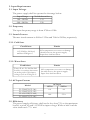
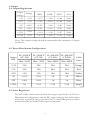
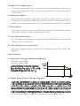
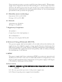
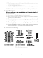
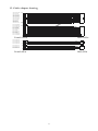
Table of Content
1. Function Description
This power supply is designed for personal computer. There are six DCoutputs:
+5V, -5V, +12V, -12V, +3.3V&+5V SB , and it provides power to all computer
systems and peripherals with maximum protection.
Here are some of the key features:
Passive Power Factor Correction(Optional)
Surge Current Protection
Input Transient Voltage Protection
Over Voltage Protection
Over Power Protection
Short Circuit Protection
Painted Aluminum Enclosure
Fanless no noise design
This power supply family is designed w/o cooling fan therefore results in
complete silence. Heat generated and raised in the power supply unit is
conducted via heatsink and finally release to the air.
2. Installation
It is rather simple to install this power supply to your precious computertower.
Follow the steps below to finish the installation.
Step1: Open the computer tower cover; put the power supply into the corresponding
location of the tower, and then use right screws to fix the power supply
to tower.
Step2: Put the Main Power Connector, ATX12V Connector, S-ATAonnector,
Peripheral Connectors and Floppy Connectors to the corresponding
male connectors of main-board, peripheral devices (i.e. HDD, CDROM
etc.) and floppy drivers respectively. When you connect connectors, please
pay attention to the orientation of them because of the different hole sizes.
Find the proper orientation and push down firmly making sure that the
pins are aligned.
1
3. Input Requirements
3.1. Input Voltage
The power supply shall be operated at the range below:
Input Range
100~120Vac
200~240Vac
Volt Selector Set
115
230
3.2. Frequency
The input frequency range is from 47Hz to 63Hz.
3.3. Inrush Current
The max. inrush current is 45A for 115Vac and 70A for 230Vac, respectively.
3.3.1. Cold Start
Conditions
115/230Vac, full load,
ambient 25degree C
Limits
NO component over stress or damage
should occur to the power supply.
Input fuse shall not blow.
3.3.2. Warm Start
Conditions
Turn off at 132/264Vac full
load for 1 secretary then turn
on at the peak of the input
voltage cycle at 25 degree C.
Limits
NO component over stress or damage
should occur to the power supply.
Input fuse shall not blow.
3.4. AC Input Current
Model
115Vac
FL-550ATX(CF-300)
FL-350ATX(CF-350)
FL-420ATX(CF-400)
FL-480ATX(CF-480)
8A
10A
AC Input
230Vac
4A
5.5A
3.5. Efficiency
The power supply efficiency shall not be less than 75% at the maximum
load of section 4.2 and 115/230Vac input voltage. While at half load the
value shall reach 77% min.
2
4. Output
4.1. Output Regulations
Output
Voltage
Range
MIN
NOM
MAX
Unit
+5V
± 5%
+4.75
+5.00
+5.00
Volts
+12V
± 5%
+11.40
+12.00
+12.60
Volts
-5V
± 10%
-4.50
-5.00
-5.50
Volts
-12V
± 10%
-10.80
-12.00
-13.20
Volts
+3.3V
± 5%
+3.14
+3.30
+3.47
Volts
+5Vsb
± 5%
+4.75
+5.00
+5.25
Volts
Note: The output voltage should be measured at the terminals of output
connector.
4.2. Power Distribution Configuration
FL-550ATX
(CF-300)
FL-350ATX
(CF-350)
FL-420ATX
(CF-400)
FL-480ATX
(CF-480)
Max. 300W
Max. 350W
Max. 400W
Max. 480W
Cable
Color
+3.3V
25A
28A
30A
30A
Orange
+5V
30A
35A
40A
45A
Red
+12V
15A
15A
18A
18A
Yellow
-5V
0.3A
0.5A
1A
1A
White
-12V
0.8A
0.8A
1A
1A
Blue
+5Vsb
2A
2.5A
2.5A
2.5A
Purple
Output
Rail
4.3. Cross Regulation
The DC l oads shall re mai n within the ranges speci fied i n 4 .2 Power
Distribution Configuration and the DC output voltages also shall remain
within the regulation ranges specified in 4.1 Output Regulations when
measured at the load end of the output connectors.
3
4.5. DC Output Voltage Ripple and Noise
DC Output
Ripple Max.
Noise Max.
Unit
+5V
75
75
mV
+12V
150
150
mV
-5V
75
75
mV
-12V
150
150
mV
+3.3V
75
75
mV
+5Vsb
100
100
mV
Note: The measurements should be made by crossing a 10uF electrolytic
and a 0.1uF ceramic disk capacitor at each output measuring bandwidth from DC to 20MHz. If ambient temperature is under 20 or
over 30, the AC input should be nominal input.
4.6. Remote ON/OFF Control
The power supply outputs shall be enabled with an active-low TTL signal.
When TTL signal is low, the DC outputs are to be enabled. When TTL
signal is high or open circuited, the DC outputs are to be disabled. Electronic
means or a mechanical switch may activate the TTL signal. After the TTL
signal is active high, must wait for 3 seconds before active low again.
on
off
AC IN
T1
PS_ON
95%
+12V
10%
+5V O/P
+3.3V
T5
T2
T3
PG
T4
4
T6
4.8. Power On Time(T1)
MAX
500
Units
ms
4.9. Rise Time(T2)
MIN.
0.1
MAX.
20
Units
ms
4.10. Power Good Delay Time(T3)
MIN.
100
MAX.
500
Units
ms
4.11. Power Good Rise Time(T4)
MAX
10
Units
ms
4.12. Hold Up Time(T5)
MIN.
14
Units
ms
The test environment is 25 degree C & full load @ nominal input.
4.13. Power Fail Signal (T6)
Power good signal shall go to a down level 1ms before +5V output voltage
falls below the regulation limits during PS-ON signal
MIN.
1
Units
ms
5. Protections
5.1. Over Voltage Protection
When the DC outputs (+5V, +12V and +3.3V) have over voltage condition,
the power supply shall provide latch mode over voltage protection.
DC Output
+12V
+5V
+3.3V
Trigger Voltage Range
13.4~15.6V
5.74~7.0V
3.76~4.3V
5
5.2. Short Circuit Protection
A short circuit placed on any output shall cause no damage or the power
supply shall shutdown. (The contact resistance is 0.05 ohm when outputs
short circuit.)
5.3. Protection Reset
When the power supply latches into shutdown condition due to a fault on
an output, the protection shall reset after the fault has been removed. Use
remote on/off control or recycle the AC power again for a typical of 3 seconds.
5.4. Over Shoot
Any output overshoot at turn on shall be less than 10% of the nominal output
value (with resistive load) as described in sec. 4.1.
5.5. Over Power Protection
At 115/230Vac input the power supply will shut down all DC output within
110% to 160% of full load.
5.6. Over Temperature Protection
The power supply shall go to latch when its inner teperat ure reaches 100
degree C.
6. Enviroment
6.1. Operation/Storage Temperature Range
Operation: 0 to 50 C
Storage: -20 C to 80 C
LOAD
100%
70%
C
C
6.2. Smart Temp. Control Feature(Option)
25
50 C
60 degree C or above, the green led goes off and the yellow one turns on,
fan that is powered by the power supply through a big 4 pin male
6
Power connector starts to rotate to pull the inner heat outside . When power
supply inner temperature decreases below 60 degree C, the fan stops, the yellow
led turns off and the green turns on again. In this way to achieve balance between
heat and noise, and realize the most possible silence of the system under
precondition the system works properly.
6.3. Humidity (none condensing)
Operation: 20% to 85% RH
Storage: 10% to 95% RH
6.4. Altitude
Operation: to 10,000 ft
Storage: to 50,000 ft
7. Regulatory Compliance
UL 60950-1
CAN/CSA-C22.2 NO.60950-1
TUV EN60950-1
FCC part 15 sub part B Class B
8. Dielectric Voltage Withstand (HI-POT)
The power supply shall withstand for 2 seconds without breakdown the
application of an 1800Vac supply voltage applied between both input line
and chassis (10mA AC Cutoff current). Isolating transformers shall similarity
withstand 4242Vdc applied between both primary and secondary windings
for a minimum of one minute.
9. MTBF
The power supply shall have a minimum MTBF at continuous operation of
50,000 hours at 100% load, the recommended ambient temperature of 25
degree C and a maximum inner temperature of the power supply at 80 degree
C for 230Vac/50Hz and 115Vac/60Hz
10. Precaution
shock!
10.1. Do not open the top cover of the power supply case.
10.2. Please keep the power supply from humidity.
7
11.3. Don't attempt to remove the front panel heat sink at any time, or it may
result in a system shutdown.
1 1 . 4 . H I G H TE M PE RA T URE ! D on ' t h an d- t ou c h an y p ar ts o f t he
enclosure while operation.
11.5. Flammable materials must keep far from the front panel heat sink.
11. Simple Maintenance
the following items:
11.1. Does power cord indeed plug into electrical outlet?
11.2.Does Input Voltage set in power supply correspond to the main
Source in your environment?
11.3 Please check the output connectors plugging in proper direction and
connecting firmly.
11.4 Please check the output connectors plugging in proper direction and
connecting firmly.
11.5. Having checked above items, if the power supply still does not function,
please send it back to your retailer or distributor for repair
12. Power Connector Drawing
+3.3VDC
+3.3VDC
+3.3VDC
COM
COM
COM
+5VDC
+5VDC
+5VDC
COM
COM
COM
+12VDC
+12VDC
+12VDC
Serial ATA
Connector
Pin-side view, not to scale
8
13. Cable adaptor drawing
20# ORANGE
18# BLUE
18# BLACK
18# GREEN
18# BLACK
18# BLACK
18# BLACK
18# W HITE
18# RED
20# RED
20# RED
20# BLACK
13
1 007 20# ORANGE
1007 20# YE LLOW
1007 20# YELLOW
1 007 18# PURPLE
1 007 18# GRAY
1 007 18# BLACK
1 007 18# RED
1 007 18# BLACK
1 007 18# RED
1 007 18# BLACK
1007 18# ORANGE
1 007 18# ORANGE
12
10 07
10 07
10 07
10 07
10 07
10 07
10 07
10 07
10 07
10 07
10 07
10 07
24
1
Female 24Pin
1007
10 07
10 07
10 07
20#
20#
20#
20#
YELLOW
YELLOW
YELLOW
YELLOW
1 007 20# BLACK
1007 20# BLACK
1007 20# BLACK
1007 20# BLACK
Male 20Pin
5
8
4
1
Female 8Pin
Male 4Pin
9