1
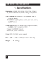
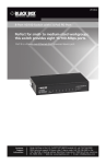
© Copyright 2008. Black Box Corporation. All rights reserved.
1000 Park Drive • Lawrence, PA 15055-1018 • 724-746-5500 • Fax 724-746-0746
JUNE 2008
AC561A-50
AC561A-150
AC561A-250
HDMI Receiver—50 m,
150 m, and 250 m
CUSTOMER SUPPORT INFORMATION
Order toll-free in the U.S.: Call 877-877-BBOX (outside U.S. call 724-746-5500)
FREE technical support 24 hours a day, 7 days a week: Call 724-746-5500 or fax 724-746-0746
Mailing address: Black Box Corporation, 1000 Park Drive, Lawrence, PA 15055-1018
Web site: www.blackbox.com • E-mail: [email protected]
FCC AND IC STATEMENTS
FEDERAL COMMUNICATIONS COMMISSION
AND
INDUSTRY CANADA
RADIO FREQUENCY INTERFERENCE STATEMENTS
This equipment generates, uses, and can radiate radio-frequency energy,
and if not installed and used properly, that is, in strict accordance with the
manufacturer’s instructions, may cause interference to radio communication.
It has been tested and found to comply with the limits for a Class A computing
device in accordance with the specifications in Subpart B of Part 15 of FCC rules,
which are designed to provide reasonable protection against such interference
when the equipment is operated in a commercial environment. Operation of
this equipment in a residential area is likely to cause interference, in which case
the user at his own expense will be required to take whatever measures may be
necessary to correct the interference.
Changes or modifications not expressly approved by the party responsible
for compliance could void the user’s authority to operate the equipment.
This digital apparatus does not exceed the Class A limits for radio noise emission from
digital apparatus set out in the Radio Interference Regulation of Industry Canada.
Le présent appareil numérique n’émet pas de bruits radioélectriques dépassant les limites
applicables aux appareils numériques de classe A prescrites dans le Règlement sur le
brouillage radioélectrique publié par Industrie Canada.
1
HDMI RECEIVER—50 M, 150 M, AND 250 M
NORMAS OFICIALES MEXICANAS (NOM)
ELECTRICAL SAFETY STATEMENT
INSTRUCCIONES DE SEGURIDAD
1. Todas las instrucciones de seguridad y operación deberán ser leídas antes
de que el aparato eléctrico sea operado.
2. Las instrucciones de seguridad y operación deberán ser guardadas para
referencia futura.
3. Todas las advertencias en el aparato eléctrico y en sus instrucciones de
operación deben ser respetadas.
4. Todas las instrucciones de operación y uso deben ser seguidas.
5. El aparato eléctrico no deberá ser usado cerca del agua—por ejemplo,
cerca de la tina de baño, lavabo, sótano mojado o cerca de una alberca,
etc..
6. El aparato eléctrico debe ser usado únicamente con carritos o pedestales
que sean recomendados por el fabricante.
7. El aparato eléctrico debe ser montado a la pared o al techo sólo como sea
recomendado por el fabricante.
8. Servicio—El usuario no debe intentar dar servicio al equipo eléctrico más
allá a lo descrito en las instrucciones de operación. Todo otro servicio
deberá ser referido a personal de servicio calificado.
9. El aparato eléctrico debe ser situado de tal manera que su posición no
interfiera su uso. La colocación del aparato eléctrico sobre una cama,
sofá, alfombra o superficie similar puede bloquea la ventilación, no se
debe colocar en libreros o gabinetes que impidan el flujo de aire por los
orificios de ventilación.
2
NOM STATEMENT
10. El equipo eléctrico deber ser situado fuera del alcance de fuentes de calor
como radiadores, registros de calor, estufas u otros aparatos (incluyendo
amplificadores) que producen calor.
11. El aparato eléctrico deberá ser connectado a una fuente de poder sólo del
tipo descrito en el instructivo de operación, o como se indique en el
aparato.
12. Precaución debe ser tomada de tal manera que la tierra fisica y la
polarización del equipo no sea eliminada.
13. Los cables de la fuente de poder deben ser guiados de tal manera que no
sean pisados ni pellizcados por objetos colocados sobre o contra ellos,
poniendo particular atención a los contactos y receptáculos donde salen
del aparato.
14. El equipo eléctrico debe ser limpiado únicamente de acuerdo a las
recomendaciones del fabricante.
15. En caso de existir, una antena externa deberá ser localizada lejos de las
lineas de energia.
16. El cable de corriente deberá ser desconectado del cuando el equipo no
sea usado por un largo periodo de tiempo.
17. Cuidado debe ser tomado de tal manera que objectos liquidos no sean
derramados sobre la cubierta u orificios de ventilación.
18. Servicio por personal calificado deberá ser provisto cuando:
A:
El cable de poder o el contacto ha sido dañado; u
B:
Objectos han caído o líquido ha sido derramado dentro del
aparato; o
C:
El aparato ha sido expuesto a la lluvia; o
D:
El aparato parece no operar normalmente o muestra un cambio en
su desempeño; o
E:
El aparato ha sido tirado o su cubierta ha sido dañada.
3
HDMI RECEIVER—50 M, 150 M, AND 250 M
TRADEMARKS USED IN THIS MANUAL
BLACK BOX and the Double Diamond logo are
registered trademarks of BB Technologies, Inc.
Any other trademarks mentioned in this manual are
acknowledged to be the property of the trademark owners.
4
CONTENTS
Contents
Chapter
Page
1. Specifications...............................................................6
2. Overview.......................................................................7
2.1 Introduction..........................................................7
2.2 Features .................................................................7
2.3 What’s Included....................................................8
2.4 Components .........................................................8
3. Installation and Operation.........................................9
3.1 Front Panel ...........................................................9
3.2 Rear Panel...........................................................10
5
HDMI RECEIVER—50 M, 150 M, AND 250 M
1. Specifications
Resolution: HDMI: 480i/480p, 576i/576p, 720p @
50/60 Hz; 1080i @ 50/60 Hz, 1080p @ 50/60 Hz
User Controls: AC561A-150: (1) Equalizer switch,
(1) Gain switch;
AC561A-250: (1) Equalizer switch, (1) Gain switch,
(1) DIP switch
Connectors: Input: (1) RJ-45 CAT5 output for video,
(1) RJ-45 CAT5 output for DDC;
Output: (1) HDMI female;
Power: (1) power connector
Power: 5 V/2.6 A DC power supply
Size: 1.2"H x 4.8"W x 4.9"D (3 x 12.3 x 12.5 cm)
Weight: 1.5 lb. (0.7 kg)
6
CHAPTER 2: Overview
2. Overview
2.1 Introduction
The HDMI Receivers (AC561A-50, AC561A-150, and
AC561A-250) work with the HDMI Transmitter
(AC560A). The HDMI over CAT5 transmitter can
extend an HDMI signal through CAT5 cables for a
distance of up to 50, 150, or 250 meters, depending on
the receiver you choose. Installing the system is quick
and easy: Simply place the receiver unit next to your
display and the transmitter next to your HDTV source
(such as a DVD player). Connect the required cables, as
described in Chapter 3.
2.2 Features
• Complies with HDMI 1.2, HDCP 1.1, and DVI 1.0
specifications.
• Supports various types of CAT5/CAT5e/CAT6
cables.
• Supports high-definition input up to 1080p.
Output resolution follows input.
• Easy to install and simple to operate.
7
HDMI RECEIVER—50 M, 150 M, AND 250 M
2.3 What’s Included
• HDMI Receiver (AC561A-50, AC561A-150,
AC561A-250)
• 5-VDC power adapter
• (4) power clips for US, Europe, UK, and Australia
• This user’s manual
2.4 Components
The receiver’s front panel includes an HDMI output
connector. All three of the AC561A models’ rear panels
have a DDC input connector, a video input connector,
and a power connector. The AC561A-150’s and AC561A250’s rear panels also have an equalizer switch and a
gain switch. The AC561A-250 also has a DIP switch.
See Chapter 3 for illustrations and component locations.
8
CHAPTER 3: Installation and Operation
3. Installation and Operation
3.1 Front Panel
Figure 3-1 shows the components on the Receiver’s front
panel. Table 3-1 describes the components’ functions.
➀
Figure 3-1. Receiver front panel.
Table 3-1. Receiver front-panel components and their functions.
Number
Component Name
➀
HDMI output
Description
Connect the HDMI output port to the HDMI
input of your display.
9
HDMI RECEIVER—50 M, 150 M, AND 250 M
3.2 Rear Panel
Figures 3-2 through 3-4 show the components on the
Receivers’ rear panels. Table 3-2 describes the
components’ functions.
➂
➃
➄
Figure 3-2. AC561A-50 receiver rear panel.
➀
➁
➂
➃
➄
Figure 3-3. AC561A-150 receiver rear panel.
10
CHAPTER 3: Installation and Operation
➅
➀
➁
➂
➃
➄
Figure 3-4. AC561A-250 receiver rear panel.
Table 3-2. Receiver rear-panel components and their functions.
Number
Component Name
Description
➀
*Equalizer
(AC561A-150
and AC561A-250
models only)
Use this switch to adjust signal enhancement
over long distance.
*NOTE: (Figure 3-2 shows the AC561A-50
model; ➀ and ➁ are not present.)
➁
*Gain
(AC561A-150
and AC561A-250
models only)
Use this switch to adjust brightness.
*NOTE: (Figure 3-2 shows the AC561A-50
model; ➀ and ➁ are not present.)
➂
DDC input
Using CAT5/CAT5e/CAT6 cable, connect the
DDC input to the transmitter’s DDC output.
NOTE: For advanced users only, if the DDC or
HDCP data are required for the source
and the display, you can use a single
CAT5 cable to connect the transmitter’s
and the receiver’s video ports.
11
HDMI RECEIVER—50 M, 150 M, AND 250 M
Table 3-2 (continued). Receiver rear-panel components and their
functions.
Number
Component Name
Description
➃
Video input
Using CAT5/CAT5e/CAT6 cable, connect the
video input to the transmitter’s video output.
➄
Power
Plug the 5-VDC power supply into the receiver
and connect the adapter to an AC wall outlet.
➅
**DIP switch
(AC561A-250
model only)
***Selects cable length: 50, 100, 150, or 250 m
**NOTE: (Figures 3-2 and 3-3 show the
AC561A-50 and AC561A-150
models; ➅ is not present.)
Table 3-3. DIP switch settings for the AC561A-250.
12
Length (meters)
DIP Switch #1
DIP Switch #2
250
UP
UP
150
DOWN
UP
100
UP
DOWN
50
DOWN
DOWN
CHAPTER 3: Installation and Operation
DVD
player
HDMI
cable
Video
(CAT5 cable)
DDC (CAT5 cable)
Transmitter
(AC560A),
front view
Transmitter
(AC560A),
rear view
HDMI display
50 m (AC561A-50)
150 m (AC561A-150)
250 m (AC561A-250)
HDMI
cable
Receiver (AC561A-50,
AC561A-150, or AC561A-250),
front view
Receiver (AC561A-50,
AC561A-150, AC561A-250),
rear view
Figure 3-5. Typical installation.
13