1
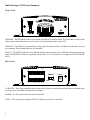
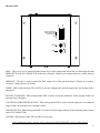
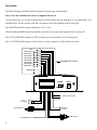
V-9989
Multi-Messager USB
Installation & User Manual
Valcom • 5614 Hollins Road • Roanoke, VA • 24019
Support: 1-800-VALCOM1 • HQ: 1-540-563-2000 • FAX: 1-540-362-9800
www.valcom.com • [email protected]
Index:
Introduction ........................................................................................................................3
Multi-Messager USB Layout Summary...............................................................................
4-5
Installation ....................................................................................................................... 6 - 9
Message Programming & Operation................................................................................. 10
Warranty & FCC ....................................................................................................................
11
Attention!
Some USB drives have indicator LEDs - These LEDs may blink slow, fast, or may stay solid during playback.
Any description in this manual about the LED is referring to the BLUE status LED on the player - NOT on the
USB drive.
Introduction:
Valcom’s Multi-Messager USB is a solid-state digital message repeater that installs easily into any messaging
application that requires a continuous, timed or triggered message play. Up to 99 messages in the MP3 format
can be stored on industry standard USB flash drives and triggered by the eight triggered inputs or a built-in timer
circuit.
Unpacking and Inspection:
Before you begin installation, unpack and verify you have all the correct parts.
(1) Multi-Messager USB
(1) USB flash drive
(2) 10-pin screw-down connectors
(1) 12VDC @ 500mA power supply
(1) Instruction manual
(1) Slotted screwdriver
(2) RCA to fly leads cable
(4) Wall mount screws
(4) Rubber feet
If you are missing any of these parts STOP and call your dealer.
Additional tools or supplies (not supplied).
(1) Phillips screwdriver
(1) Wire strippers
(1) CAT 3/5 wire for wiring screw-down connectors.
3
Multi-Messager USB Layout Summary:
Front of Unit
SPEAKER - The SPEAKER switch can be turned ON and OFF to monitor audio. The switch has no effect on the
audio output connections on the rear of the unit. Switch should normally be kept OFF.
USB PLUG - The USB drive is inserted here to play audio. If insertion of drive is difficult, turn the drive over and
try reinserting. Drive should slide into jack smoothly.
STATUS - The STATUS indicator is a LED that during normal operation with a USB drive inserted into the unit
will be SOLID BLUE. If there is a problem with the drive, it is not inserted or it is empty, the LED will BLINK
BLUE.
STOP
7
8
6
5
3
4
1
2
GND
Rear of Unit
- OUT
+ OUT
ACT
GND
BGM
N/C
600Ω
600Ω
8Ω
GND
POWER
OFF
ON
12VDC
500mA
I/O BLOCK - This 20-pin modular header accepts two 10-pin screw-down socket blocks that are included in the
accessory pack. For further instructions turn to page 6.
POWER - Use this switch to turn the unit ON and OFF.
12VDC - This is where the supplied 12VDC @ 500mA power pack is connected.
4
Timer
{
1 2 3 4 5 6 7 8 9 10
Trigger Polarity NC/NO
Continuous/Play Once
Rotate/Standard
OFF
ON
Bottom of unit
+
Message
BGM
+
-
BGM - This pot is used to control the final output level of the background music that is fed through the units
BGM INPUT on the I/O CONNECTOR on the rear of the unit. Volume up is counter-clockwise, volume down is
clockwise.
MESSAGE - This pot is used to control the final output level of the stored messages. Volume up is counterclockwise, volume down is clockwise.
TIMER - DIP switch positions SW1 to SW4 are used to configure the stored message timer for message slots 9
through 99.
ROTATE/ STANDARD - DIP switch position SW5 is used to select the standard or rotate message feature for
message slots 1 through 8.
CONTINUOUS TRIGGER/PLAY ONCE - DIP switch position SW6 is used to select the play once or continuous
trigger feature for message slots 1 through 8 ONLY.
TRIGGER NC/NO - DIP switch position SW7 is used to select the trigger polarity of the incoming contact closure
on the I/O CONNECTOR.
UNUSED - DIP switches SW8, SW9 & SW10 are not used.
A full explanation of these settings can be found in the PROGRAMMING section of this manual.
5
Installation:
The Multi-Messager should be installed using the following steps outlined below:
Step 1: Wire the terminal blocks that are supplied with the kit.
Use the chart below to wire the terminal blocks for the features that are applicable to your application. Two
terminal blocks, two RCA audio cords and a screwdriver have been supplied in the accessory kit.
The TRIGGER & STOP terminals should use CAT 3/5 wire.
The 8Ω, 600Ω and BGM connections should use the RCA to fly leads cable suppled in the accessory kit.
The ACTIVE TRIGGER output & 12VDC auxiliary power out should use 22 or 24 gauge wire.
The ACTIVE TRIGGER output is rated at 25mA. A relay is required if 25mA will be exceeded.
STOP
MESSAGE 8
MESSAGE 7
MESSAGE 6
MESSAGE 5
MESSAGE 4
MESSAGE 3
MESSAGE 2
MESSAGE 1
Example NO Circuit
STOP
7
8
6
5
3
4
1
2
GND
GROUND
- OUT
+ OUT
ACT
GND
BGM
N/C
600Ω
600Ω
8Ω
GND
POWER
OFF
ON
8Ω
SPEAKER
+
-
12VDC
500mA
12VDC AUX @ 250mA
+
600Ω LINE OUT
+
ACTIVE ACTIVE +
-
NO CONNECTION
6
BGM LINE IN
+
Step 2: Set the DIP switches for the features that will be used.
The Mutli-Messager USB has several features that are activated by setting the DIP switches on the bottom of
the unit. Changes to these DIP switches must be done with the power OFF.
TIMER - DIP switch positions SW1 to SW4 are used to configure the stored message timer for message slots 9
through 99. Use the chart below to configure the timer, if no timer is required turn all switches to the OFF position.
Time Interval
Timer OFF
10 seconds
20 seconds
30 seconds
45 seconds
1 minute
2 minutes
3 minutes
4 minutes
5 minutes
10 minutes
15 minutes
20 minutes
30 minutes
45 minutes
60 minutes
SW1
OFF
ON
OFF
ON
OFF
ON
OFF
ON
OFF
ON
OFF
ON
OFF
ON
OFF
ON
SW2
OFF
OFF
ON
ON
OFF
OFF
ON
ON
OFF
OFF
ON
ON
OFF
OFF
ON
ON
SW3
OFF
OFF
OFF
OFF
ON
ON
ON
ON
OFF
OFF
OFF
OFF
ON
ON
ON
ON
SW4
OFF
OFF
OFF
OFF
OFF
OFF
OFF
OFF
ON
ON
ON
ON
ON
ON
ON
ON
For example: Slots 10, 25, & 50 have messages, AND the switch settings on the bottom of the unit are set for 10
minutes. During normal operation triggered messages will play on demand, but every 10 minutes ONE of the
timed messages will play . . . first slot 10 will play then wait 10 minutes . . . then slot 25 will play . . . wait 10
minutes . . . then slot 50 . . . wait 10 minutes . . . then slot 10 . . . and so on. If BGM music is used, then it will fade
down to play the message then fade back up after the message is played.
ROTATE/STANDARD - DIP switch position SW5 is used to select the standard or rotate message feature for
message slots 1 through 8.
When this DIP switch is set to “ON” the unit will rotate through the messages on each triggering of input TRIGGER
1. For example, the first time TRIGGER 1 is activated message 1.mp3 will play, the next time TRIGGER 1 is
activated message 2.mp3 will play, and so on. Triggering of TRIGGER 2 through 8 will have no effect.
When this DIP switch is set to “OFF” the unit will trigger normally - Normally is defined as any one of the
eight contact closures that are activated will trigger the corresponding message. Example TRIGGER 1 will play
message 1.mp3, TRIGGER 2 will play message 2.mp3, and so on. The unit has 8 triggered inputs.
Note: If you only have one message on the unit then STANDARD or ROTATE will have the same effect.
7
CONTINUOUS TRIGGER/PLAY ONCE - DIP switch position SW6 is used select the play once or continuous
trigger feature for message slots 1 through 8 ONLY.
When this DIP switch is set to “ON” the unit will play message selected continuously, as long as trigger is
applied.
When this DIP switch is set to “OFF” the unit will play message selected once, then stop until triggered again.
Note: This has no effect on message slots 9 through 99.
TRIGGER NC/NO - DIP switch position SW7 is used to select the trigger polarity of the incoming contact on the
I/O CONNECTOR.
When this DIP switch is set to “ON” all incoming triggers are set to normally-closed triggering. The unit will play
a message when the trigger input is lifted from ground. The unit will also STOP playing the current message if the
STOP TRIGGER is lifted from ground.
When this DIP switch is set to “OFF” all incoming triggers are set to normally-open triggering. The unit will play
a message when the TRIGGER input for that specific message is brought to ground. The unit will also STOP
playing the current message if the STOP TRIGGER is brought to ground.
Important note for normally-closed triggering : When using normally-closed triggering, all trigger inputs
including the stop trigger must be tied to ground. Failure to do so will cause undesired operation.
UNUSED - DIP switches SW8, SW9 & SW10 are not used.
8
Step 3: Install Multi-Messager USB hardware
Step 3.1: Wall or shelf mount the unit. Screws and rubber feet are supplied in the accessory kit.
Step 3.2: Verify power switch on rear of unit is in OFF position. Attach the included power pack to a wall
or power strip receptacle, then attach the other end to the jack on the rear of the unit labeled 12VDC.
Tip: Make sure the power receptacle is live 24 hours a day and is not switched off at night.
Step 3.3: If connecting unit to an amplifer make sure it is turned OFF for this part of the installation.
Step 3.4: Connect the 10-pin socket blocks to the headers on the rear of the unit. This wiring should have been
done in a previous step - if not completed go to the WIRING DIAGRAM section of this manual (page 6).
Warning: Connection of a P.A. amplifiers OUTPUT to any connections on this unit will cause damage and void
the warranty.
Step 3.5: Insert the USB flash drive into the front of the unit. Do not force the USB flash drive - if it does not fit
in one way, try turning it over and reinserting.
Step 3.6: Turn the power switch on rear of unit to the ON position. After the unit initializes the STATUS LED on
the front of unit will turn solid blue. This process may take up to 15 seconds.
Step 3.7: Push the SPEAKER switch located on the front of the unit to the IN position. This speaker is for verifying audio playback and testing purposes only – DO NOT use this for setting the OUTPUT volume level!
Step 3.8: If any amplifiers were turned OFF during installation turn them back ON now.
Step 3.9: If a background music source is not being fed through the unit then skip to the next step. Adjust the
volume level pot labeled BGM on the bottom of the unit using the included screwdriver. DO NOT use the internal
speaker on the unit to set this level - listen to the speaker(s) connected to the output of the unit or output of the
P.A. amplifier .
If an acceptable volume level can not be achieved or audio is distorted/muffled, then take the following steps:
a.
b.
c.
d.
e.
f.
Turn down (clockwise) the pot labeled BGM on the bottom of the unit.
Turn the volume level UP on the stores PA amplifier.
Turn up (counter-clockwise) the pot labeled BGM on the bottom of the unit.
Keep repeating above procedure until level is acceptable or go to step e.
Move the RCA plug from the 8Ω to 600Ω or 600Ω to 8Ω output on the rear of the unit.
Repeat step a through d.
Step 3.10: Trigger one of the stored messages either by contact closure or timed message interval. If volume
levels are low or high, the pot labeled MESSAGE on the bottom of the unit may need to be adjusted. MESSAGE volume down is clockwise, MESSAGE volume up is counter-clockwise.
Step 3.11: Push the SPEAKER switch to the OUT position.
9
Message Programming & Operation:
All messages that are available for the Multi-Messager USB to play are stored on an industry standard USB flash
drive. Messages must be labeled correctly so they will automatically be placed into virtual message “slots” on the
unit. There are two different type of message slots:
1. Triggered Message Slots – These messages reside in slots 1 to 8 of the USB flash drive and are activated
instantly when the corresponding contact closure is activated.
2. Timed Message Slots – These messages reside in slots 9 – 99 of the USB flash drive and are activated by a
built-in timer circuit.
Messages are placed onto the USB flash drive using a standard computer and dragging and dropping new audio
from the computer to the USB flash drive.
Messages MUST be labeled in the following manner: “slot position_number”.mp3
For example, if you wanted a file named “sound_effect.mp3” put into slot eight, then it would need to renamed
as file “8.mp3”.
A typical list of messages on the USB flash drive would look like this:
1.mp3
2.mp3
8.mp3
10.mp3
36.mp3
The above list would allow messages 1.mp3, 2.mp3 & 8.mp3 to be triggered by the contact closures while 10.mp3
and 36.mp3 would be played on a time interval. The time interval would be set with the DIP switches on the
bottom of the unit.
If the USB drive ever needs to be erased completely, it can be formatted using your computer. Drives smaller than
512MB can be formatted using FAT, and drives 512MB or larger can use FAT32.
MPEG files must be recorded with a Bit Rate between 8Kbps and 128 Kbps and a Sample Rate between 16KHz
and 48KHz.
10
Limited Warranty
Valcom, Inc. warrants its products to be free from defects in materials and workmanship underconditions of normal use and service
for a period of one year from the date of shipment. The obligation under this warranty shall be limited to the replacement, repair or
refund of any suchdefective device within the warranty period, provided that:
1.inspection by Valcom, Inc. indicates the validity of the claim,
2.the defect is not the result of damage, misuse, or negligence after the original shipment,
3.the product has not been in any way repaired by others and that factory sealed units are unopened.(A service charge plus parts and
labor will be applied to units defaced or physically damaged).
4.freight charges for the return of products to Valcom, Inc. are prepaid,
5.all units “out of warranty” are subject to a service charge. The service charge will cover minor repairs(major repairs will be subject
to additional charges for parts and labor).
This warranty is in lieu of and excludes all other warranties expressed or implied, and in noevent shall Valcom, Inc. be liable
for any anticipated profits, consequential damages, loss oftime or other losses incurred by the buyer in connection with the
purchase, operation or useof the product.
This warranty specifically excludes damage incurred in shipment. In the event a product isreceived in damaged condition, the carrier
should be notified immediately. Claims for suchdamage should be filed with the carrier involved in accordance with the F.O.B.
point.
CONTACT: Please contact Valcom at the address and phone number below to receive a return authorization number and to arrange
for the repair or replacement covered by this warranty. Please indicate the Product’s serial number in all correspondence or a RMA
authorization number in the absence of a serial number. Valcom, Inc., 5614 Hollins Road, Roanoke, VA 24019, Phone: 540-5632000.
FCC Part 15 : This equipment has been tested and found to comply within the limits for a Class A digital device, pursuant to Part
15 of the FCC rules. These limits are designed to provide reasonable protection against harmful interference when the equipment is
operated in a commercial environment. This equipment generates, uses and can radiate radio frequency energy and, if not installed
and used in accordance with the instruction manual, may cause harmful interference to radio communications. Operation of the
equipment in a residential area is likely to cause harmful interference in which case the user will be required to correct interference at
his own expense. In order to maintain compliance with FCC regulations shielded cables must be used with this equipment. Operation
with non-approved equipment or unshielded cables is likely to result in interference to radio & television reception.
IC ES 003 : This Class A digital apparatus complies with Canadian ICES-003 C et appareil numérique de la classe A est conform e
à la norme NMB-003 du Canada.
CE CONFORMITY : The Multi-Messager USB conforms with the following standards, in accordance with the EU Safety, EMC
Emissions, & EMC Immunities : EN 60950-1:2001, EN 55022:1998 for Class A, EN 55024:1998 + A1:2001 + A2:2003, EN 610004-2:1995 + A1:1998, EN 61000-4-3:1995, EN 61000-4-4:1995, EN 61000-4-5:1995, EN 61000-4-6:1996, EN 61000-5-11:1994.
11
5614 Hollins Road
Roanoke, VA 24019
Support: 1-800-VALCOM1
HQ: 1-540-563-2000
Fax: 1-540-362-9800
www.valcom.com
[email protected]
Rev. A - 04/07