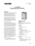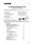
1
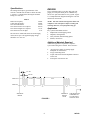
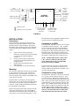
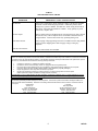
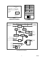
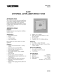
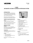
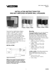
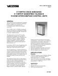
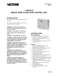
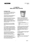
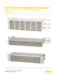
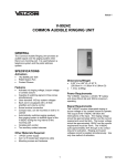
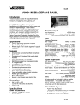
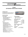
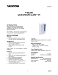
VSP-V-9923B
Issue 4
V-9923B
CODE CALL UNIT
INTRODUCTION
This manual provides instructions for identification,
installation, operation, and technical assistance for
the Valcom V-9923B Code Call Unit.
The V-9923B provides two or three digit code call
paging via a loop start trunk port on a PABX or by
the use of a spare line button on a key system.
The V-9923B code call unit complies with Part 68 of
the FCC Rules and Regulations and has been granted
FCC Registration #BAFUSA-68753-KX-N. The
ringer equivalence is 0.1B and the unit requires a
USOC RJ21X connector.
•
•
•
•
In accordance with FCC Rules and applicable tariffs,
this code call unit may only be installed with the
authorization of the owner of the host system.
•
The FCC Registration #BAFUSA-68753-KX-N, will
be listed in the affidavits filed with the telephone
company; it will also be recorded in the system log
kept by installation and maintenance personnel. The
local telephone company is to be notified of the FCC
registration number when this code call unit is
installed.
•
•
Dial tone to calling party
Coded tone output for paging systems
Switch controlled code verification tone
Automatically discontinues code sending when
answered
Capable of being used with another V-9923B to
provide two link operation
Uses standard 1A2 key system voltages
Mounts on the wall, in a key cabinet, or in the
PABX Cabinet
Capacity
Each V-9923B Code Call Unit provides the necessary
equipment for 1 link of code call. For an additional
link of code call, another V-9923B is required (two
links maximum).
SPECIFICATIONS
The V-9923B is capable of providing code signaling
for paging purposes; it provides for "meet me"
answer of code call and provides talk circuit and
signaling tone.
Dimensions
Features
Power Requirements
•
•
•
•
7.1"H x 5.9"W x 2.1"D
(18.03cm H x 14.99cm W x 5.33cm D)
Trunk level access on PABX's, station level
answer
Can be used with 1A2 type key systems
81 two digit codes or 729 three digit codes
Uses rotary or tone dial signaling
Range
"A" Battery
The Valcom V-9923B requires –24 Vdc talk
battery and –24 Vdc signal battery. The current
consumption and voltage range is shown in Table 1.
"B" Battery
Table 1
Idle
Operating
–21.5 to –26 Vdc 65mA
–21.5 to –26 Vdc 125mA
Nominal Timing and Frequency
1
947923
Specifications
DESIGN
The timing and frequency specifications of the
Valcom V-9923B code call unit are shown in Table
2. Figure 1 is a timing chart showing the nominal
timing of a code call.
Table 2
Dial Tone Frequency
Coded Tone Frequency
Time Tones Broadcast
Time between tones in a sequence
Time between digits in a sequence
Time between series of digits
The V-9923B provides two or three digit code call
paging via a loop start trunk port on a PABX or by
the use of a spare line button on a key system. Figure
2 is a simplified block diagram showing the code call
unit and its connections.
180 Hz
550 Hz
370 ms
500 ms
1.5 sec
8 sec
NOTE: The code call unit is designed so that it will
complete a code call sequence before resetting and
returning dial tone, even if all parties hang up.
Application
Key systems and PABX's used in:
• Department stores/shopping centers
• Hospitals, nursing homes
• Noisy locations, manufacturing plants
• Schools, universities
The Valcom V-9923B will detect 20-30 Hz ringing
on the answer port. The applied ringing voltage
should be 75 to 125 Vac.
Additional Materials Required
Additional equipment is required to complete a
system when using the V-9923B. These items are:
•
•
•
•
-24 Vdc power supply (if existing supply
inadequate or non-existent)
66 type connecting block
25 pair cable with a female amphenol connector
on one end
twisted pair crossconnect wire
.37 sec.
.50 sec.
TONE ON
1.5 sec.
1.5 sec.
8 sec.
TONE OFF
"3"
"1"
"2"
"3"
SEQUENCE
BEGINS
SEQUENCE
BEGINS
AGAIN
FIGURE 1
2
"1"
CONTINUES UNTIL
ANSW ERED OR
CALLING PARTY
GOES ON HOOK
947923
PBX
OUTGOING LOOP
START CO TRUNK
T
Y
R
TO
ACCESS
PORT
ANSW ER
PORT
RO
TT
SPARE LINE BUTTON
ON KEY TELEPHONE
10K
V-9923B
CODE CALL
INH
RT
IN
L
OUT
Y
AB
AG BB
BG LS
EP1
X
ANALOG
PBX
STATION
CIRCUIT
TONE OUTPUT
TO PAGING
SYSTEM
SW ITCHED
RELAY
OUTPUT
EP2
Y
X
USED W ITH PBX
Y
USED W ITH 1A2 KEY SYSTEM
TO –24 Vdc AND
10 Vac POW ER
SUPPLIES
TO NEXT V-9923B
CODE CALL UNIT
IF EQUIPPED
FIGURE 2
all connections before plugging the amphenol end of
the cable into the V-9923B code call unit.
INSTALLATION
Precautions
All precautions have been taken at the factory to
insure that the equipment functions properly when
installed correctly. Please follow the precautions
listed below before applying power to the equipment
or the equipment may be damaged and the warranty
voided.
a)
b)
c)
d)
Connections to PABX
The connections required to connect the V-9923B
to a PABX are shown in Figure 4. The V-9923B
requires a loop start trunk port from the PABX for
access. If more than one link of code call is being
provided, the second V-9923B would require a trunk
also and the two trunks should be in a hunt group
within the PABX. This arrangement allows access to
the second V-9923B if the first V-9923B is in use.
If power was previously connected,
disconnect or remove power before inserting
or removing unit from the amphenol
connector.
Exercise caution when crossconnecting
wires that two adjacent terminals are not
bridged together.
Double check all connections before
applying power.
Use twisted pair wire for all connections.
NOTE: ADVISE PERSONNEL USING CODE
CALL UNIT TO ALWAYS WAIT FOR DIAL
TONE FROM CODE CALL UNIT BEFORE
DIALING IN CODE NUMBER!
To answer the code call requires a station from the
PABX. If two code call units are being used, two
stations would be required and they would have to be
in a rotary hunt group also.
Mounting
The Valcom V-9923B code call unit may be mounted
in a key cabinet relay rack or on the wall near the
distribution frame. When choosing a location, it is
necessary that the loop resistance of the PABX or key
system are not exceeded.
Connections to Key Systems
The connections required to connect the V-9923B
to a 1A2 key system are shown in Figure 5. The T,
R, A and L leads are multiplied to all phones in the
system. Use a spare pick-up button and install a 10K
Ohm 1/4 watt 5% resistor either in the phone or at the
connecting block in series with the A lead from each
phone. The V-9923B will discontinue the code call
paging when it recognizes two phones off hook with
two 10K Ohm resistors to ground on the A leads.
NOTE: WHEN USING 1A2 KEY TELEPHONES,
THE TO AND RO LEADS THAT WERE USED
FOR PABX CONNECTION ARE NOT USED.
Mount the unit in a vacant space in an equipment
cabinet, rack, or key system cabinet, allowing enough
room at the rear of the unit to plug in an amphenol
connector. Mount a 66B type punchdown block near
the unit and label it per Figure 3.
Run a 25 pair cable with a female connector from the
unit to the connecting block. The cable should be
terminated on the connecting block in standard color
code order on a row of the connecting block. Verify
3
947923
The calling party then dials in a two or three digit
number depending upon the position of dipswitch #1
on the code call unit. After the last digit the code call
unit begins to transmit tone via the TT and RT leads
and the contact on the IN and OUT leads closes in
conjunction with the tones. The unit continues to
broadcast the codes until it is released by the calling
party going on hook or by someone answering the
code call.
Power Connections
The connections required to connect the V-9923B to
a power supply are shown in Figure 6. Correct
polarity must be observed for the unit to function
properly.
Output Connections
The V-9923B contains a tone generator and isolation
transformer to allow direct hook-up to the paging
system amplifier. The tones are applied to the output
in the coded sequence dialed into the unit. The tones
appear on the TT, (BK/S, pin 29) and the RT (S/BK,
pin 30) leads. If tones are not required as in the case
of using claxton horns, bells, buzzers, lamps, etc. a
contact closure is available. The contact is capable of
handling 1 amp @ 125 Vac or 2 amps @ 30 Vdc.
Higher current requirements should use the contact to
operate a power relay, which would switch the load.
The switched make contact input is the IN lead
(BL/BK, pin 22) and the out lead is the OUT lead
(BK/BL, pin 21).
When the unit is being used by a PABX, the ringing
voltage on the TO and RO leads from the PABX
station releases the code call unit and connects the
PABX trunk (access) to the PABX station (answer).
If the unit is being used with 1A2 key telephones,
when the second party goes off hook on the code call
button, the combined voltage drop across the 10K
Ohm resistors in the A leads releases the code call
unit.
The code call unit is designed so that it will finish
broadcasting a code before returning dial tone and
resetting even if answered in the middle of the code
call sequence.
When the switched output of the V-9923B is used to
operate a DC slave relay, it is necessary to install a
spike suppression diode in parallel with the coil of the
relay. Refer to Figure 7 for the appropriate
connections.
Figure 9 is a simplified schematic illustrating the
main control functions contained in the V-9923B.
TECHNICAL ASSISTANCE
Option Switches
Four option switches are located through the back of
the unit near the amphenol.
When trouble is reported, verify power is being
supplied to the unit and there are no broken
connections. Be sure the amphenol is secure in the
back of the unit and the cable is terminated correctly
on the crossconnect block. Check voltages for proper
polarity on crossconnect block. If a spare unit is
available, continue to troubleshoot by substituting the
spare unit for the suspected defective unit.
Switch 1 sets either two or three digit operation.
Switch 2 allows or disallows the calling party to hear
the tones as they are sent.
Switch 3 must be left in the ON position.
Switch 4 is for flashing or solid lamp indication on
access (1A2 key systems only).
Refer to Figure 8 for Option Switch Settings.
Assistance in troubleshooting is available from the
factory. When calling, you should have a VOM, a
telephone test set, and several clip leads available and
be calling from the job site. Call (540) 563-2000 and
ask for Technical Support, or call (540) 427-6000 for
Valcom 24-hour Automated Support or visit our
website at http://www.valcom.com.
Two Link Connection
If more than one V-9923B is being used to provide
two link operation, strap EP1 lead from first unit to
EP2 lead of second unit. Strap EP2 lead of first unit
to the EP1 lead of the second unit. A maximum of
two links is all that is possible.
Valcom equipment is not field repairable. Valcom,
Inc. maintains service facilities in Roanoke, VA.
Should repairs be necessary, attach a tag to the unit
clearly stating company name, address, phone
number, contact person, and the nature of the
problem. Send the unit to:
OPERATION
The code call unit is accessed by placing a telephone
or a resistive short across T and R. The unit will
return dial tone to the calling party when it is ready to
accept digits.
NOTE: IN TWO LINK OPERATION, DIAL
TONE WILL BE WITHHELD FROM THE
SECOND LINK UNTIL THE CODE CALL ON
FIRST LINK IS ANSWERED TO PREVENT TWO
CODES BEING BROADCAST
SIMULTANEOUSLY.
Valcom, Inc.
Repair and Return Dept.
5614 Hollins Road
Roanoke, VA 24019-5056
4
947923
TABLE 3
TROUBLESHOOTING CHART
PROBLEMS
PROBABLE CAUSES AND SOLUTIONS
No dial tone.
Verify power connections; check operation of unit by placing test telephone
across the T and R leads and going off hook. If dial tone present, check
wiring to key system or PABX. If no dial tone, check wiring of EP leads to
other units. Verify that all grounds are common. Verify polarity of power
connections. Replace unit.
No tone output.
Remove leads on the TT and RT leads on crossconnect block. Place call into
the unit and verify with a telephone across TT and RT leads that tones are
being broadcast. Listen to unit to hear relay operating during code.
Unit doesn't answer.
Verify ringing voltage appearing across the TO and RO leads if using PABX
or that A lead is dropping below half of supply voltage if using key
telephone.
Unit cuts off on answer.
Reverse station leads on TO and RO.
VALCOM LIMITED WARRANTY
Valcom, Inc. warrants its products to be free from defects in materials and workmanship under conditions of normal use and service
for a period of one year from the date of shipment. The obligation under this warranty shall be limited to the replacement, repair or
refund of any such defective device within the warranty period, provided that:
1.
2.
3.
inspection by Valcom, Inc. indicates the validity of the claim,
the defect is not the result of damage, misuse, or negligence after the original shipment,
the product has not been altered in any way or repaired by others and that factory sealed units are unopened
(A service charge plus parts and labor will be applied to units defaced or physically damaged),
4.
freight charges for the return of products to Valcom are prepaid,
5.
all units 'out of warranty' are subject to a service charge. The service charge will cover minor repairs
(Major repairs will be subject to additional charges for parts and labor).
This warranty is in lieu of and excludes all other warranties, expressed or implied, and in no event shall Valcom, Inc. be
liable for any anticipated profits, consequential damage, loss of time or other losses incurred by the buyer in connection
with the purchase, operation or use of the product.
This warranty specifically excludes damage incurred in shipment. In the event a product is received in damaged condition, the
carrier should be notified immediately. Claims for such damage should be filed with the carrier involved in accordance with the
F.O.B. point.
Headquarters:
In Canada:
Valcom, Inc.
CMX Corporation
5614 Hollins Road
35 Van Kirk Drive #11 and 12
Roanoke, VA 24019-5056
Brampton, Ontario L7A1A5
Phone: (540) 563-2000
Phone: (905) 456-1072
FAX: (540) 362-9800
FAX: (905) 456-2269
5
947923
CB-1
A
PBX AND
KEY SYSTEM
INPUT
ANALOG PBX
ANSWER PORT
SWITCHED
RELAY
OUTPUT
TONE
OUTPUT
EXPANSION
CIRCUIT
POWER
SUPPLY
W/BL
BL/W
W/O
O/W
W/G
G/W
INH
W/BR
TO
BR/W
RO
W/S
S/W
R/BL
BL/R
R/O
O/R
R/G
G/R
R/BR
BR/R
R/S
S/R
OUT BK/BL
BL/BK
IN
BK/O
O/BK
BK/G
PC G/BK
BK/BR
BR/BK
BK/S
TT
RT S/BK
Y/BL
BL/Y
Y/O
O/Y
Y/G
G/Y
Y/BR
BR/Y
Y/S
S/Y
V/BL
BL/V
EP1 V/O
EP2 O/V
V/G
G/V
AG V/BR
AB BR/V
BG V/S
BB S/V
T
R
L
LS
B
26
1
27
2
28
3
29
4
30
5
31
6
32
7
33
8
34
9
35
10
36
11
37
12
38
13
39
14
40
15
41
16
42
17
43
18
44
19
45
20
46
21
47
22
48
23
49
24
50
25
C
D
E
F
1
2
3
4
5
6
7
8
9
10
11
12
13
14
15
16
17
18
19
20
21
22
23
24
25
26
27
28
29
30
31
32
33
34
35
36
37
38
39
40
41
42
43
44
45
46
47
48
49
50
66B350
FIGURE 3
6
947923
PART OF PBX
LOOP START
OUTGOING C.O.
TRUNK
(ROTARY OR T.T.)
T W/BL (1)
R BL/W (2)
T
R
TO W/BR (7)
RO BR/W (8)
T
PBX ANALOG
STATION PORT
R
FIGURE 4
CONNECTIONS OF V-9923B TO PABX
PART OF KEY TELEPHONE
INSTRUMENT
V-9923B
PART OF CONNECTING
BLOCK ROW B
P.U.
T W/BL (1)
R BL/W (2)
T
R
(6)
L
INH G/W
L W/O
LG
LS O/W
(4)
A
H.S.
N
E
T
10K
A1
(3)
TO 10 Vac ON
POWER SUPPLY
TO REST OF
KEY STRIP
FIGURE 5
CONNECTION OF V-9923B TO KEY SYSTEM
V-9923B
PART OF CONNECTING
BLOCK - ROW B
10 Vac
NOTE 1
LS
O/W (4)
LG
AG GROUND
NOTE 2
IN
BL/BK (22)
AG
V/BR (47)
AB -24 Vdc
AB
BR/V (48)
BG GROUND
BG
V/S
(49)
BB -24 Vdc
BB
S/V
(50)
NOTES:
1. LS CONNECTED TO 10 Vac ONLY WHEN
USING KEY TELEPHONE.
2. IF SWITCHING OUTPUT IS BEING USED
INSTEAD OF TONE OUTPUT, STRAP IN
LEAD TO OUTPUT TO BE SWITCHED.
IF TONE OUTPUT IS USED, IN LEAD
HAS NO CONNECTIONS.
FIGURE 6
POWER SUPPLY CONNECTIONS
7
947923
SW
BL/BK
2
OUT
3 DIGIT CODES: 111-119, 121-129,
...., 991-999
FIGURE 7
CONNECTIONS OF V-9923B FOR
OPERATING A DC SLAVE RELAY
T
26
R
1
OFF ON
FIGURE 8
OPTION SWITCH SETTINGS
TO
29
K2
K3
LINE
SUPERVISION
K2
BATTERY
FEED
TONE OR ROTARY
PULSE DECODING
"A" LEAD OF LINE BUT.
K1
OSC. AND
AMPLIFIER
LOGIC AND
MEMORY
K1
K1
LS
2
L
27
RO
4
TO ANALOG
STATION OF
PBX (ANSW ER)
RING
DETECTOR
K2
LAMP ON LINE BUT.
SOLID
LAMP
2 DIGIT CODES: 11-19, 21-29, ., 91-99
DC Power Supply
depends on relay
requirements
LAMP SUPPLY
FLASHING
LAMP
4
(Portion of
Connecting
Block)
TO PBX TRUNK OR
SPARE LINE BUTTON
ON TELEPHONE
(ACCESS)
MUST BE IN THE ON POSITION
3
Relay Coil
IN
ON
THREE DIGIT
OPERATION
CODE
NO CODE
VERIFICATION VERIFICATION
1
Diode 1N4003 or eq.
BK/BL
OFF
TWO DIGIT
OPERATION
TT
40
RT
15
OUT
36
IN
11
TONE
OUTPUT
SW ITCHED
RELAY
OUTPUT
K4
INHIBIT
CIRCUIT
INH
3
K3
CONTROL
CIRCUIT
EP1
47
EP2
22
TO NEXT
V-9923B
A GND.
A BATT.
B GND.
B BATT.
VOLT
REG.
FIGURE 9
V-9923B SIMPLIFIED SCHEMATIC
8
947923