1
INSTRUCTION
MANUAL
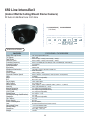
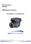
650Line Intensifier3™ Series
HT7246IHR / HT7247IHR / HT7250IHR
(Weatherproof Dome Camera with Chameleon™ Cover)
HTINTB8 / HTINTB9 / HTINTB10
(Weatherproof Bullet Camera with mount plate)
HTINTD8 / HTINTD9 / HTINTD10
(Weatherproof Dome Camera)
HT647HRTP
(Miniature Weatherproof Dome Camera with Chameleon™ Cover)
CVC6245IHR
(Indoor Wall & Ceiling Mount Dome Camera)
CVC6246IHR
(Indoor Wall & Ceiling Mount Dome Camera)
HTINTT5
(Traditional Box type Camera)
Speco Technologies is constantly developing product improvements.
We reserve the right to modify product design and specifications without notice and without incurring any obligation.
Rev. 6/20/2012
Contents
◑
Contents....................................................... 1
◑
Precautions.................................................. 2, 3
◑
Safety Instructions....................................... 4
◑
Package Contents........................................ 5
◑
Camera Installation...................................... 6-13
◑
Specifications............................................... 14-20
◑
Camera Dimension...................................... 21-23
◑
Features....................................................... 24-25
◑
OSD Menu Details....................................... 26- 37
◑
Trouble Shooting.......................................... 38
1
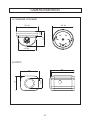
Precautions
Do not install the camera in
extreme temperature conditions.
Only use the camera under conditions
where temperatures are between
-10°C and +50°C. Be especially careful to
provide ventilation when operating under
high temperatures.
Never keep the camera pointed
directly at strong light.
It can cause malfunctions to occur.
Do not install the camera under
unstable lighting conditions.
Severe lighting change or flicker can
cause the camera to work improperly.
Do not drop the camera or subject
it to physical shocks.
Housing damage can compromise
weatherproof ratings.
Do not touch the front lens of the
camera.
This is one of the most important parts of
the camera. Be careful not to leave
fingerprints on the lens cover.
Do not expose the camera to
radioactivity.
If exposed to radioactivity the CCD
will fail.
NOTE
* If the camera is exposed to spotlight or object reflecting strong light,
smear or blooming may occur.
* please check that the power satisfies the normal specification before
connecting the camera.
2
CAUTION
CAUTION
RISKOF
OFELECTRIC
ELECTRICSHOCK
SHOCK
RISK
DONOT
NOTOPEN
OPEN
DO
CAUTION
RISK OF ELECTRIC SHOCK
DO NOT OPEN
CAUTION:TO
CAUTION:TOREDUCE
REDUCETHE
THERISK
RISKOF
OFELECTRIC
ELECTRIC
SHOCK REDUCE THE RISK OF ELECTRIC SHOCK
CAUTION:TO
SHOCK
DO NOT REMOVE COVER(OR BACK).
DONOT
NOTREMOVE
REMOVECOVER(OR
COVER(ORBACK).
BACK).
DO
NO USER-SERVICEABLE PARTS INSIDE.
NO
USER-SERVICEABLE
PARTS
INSIDE.
NO USER-SERVICEABLE PARTS INSIDE.
REFER SERVICING TO QUALIFIED SERVICE PERSONNEL.
REFERSERVICING
SERVICINGTO
TOQUALIFIED
QUALIFIEDSERVICE
SERVICEPERSONNEL.
PERSONNEL.
REFER
ISO14001
ISO14001
ISO14001
The lightning flash with an arrowhead symbol, within an equilateral
triangle is intended to alert the user to the presence of uninsulated
dangerous voltage within the product's enclosure that may be of
sufficient magnitude to constitute a risk of electric shock to persons.
The exclamation point within an equilateral triangle is intended to alert
the user to the presence of important operating and maintenance
(servicing) instructions in the literature accompanying the appliance.
In USA and Canada, Use Class 2 Power Supply Only
INFORMATION - This equipment has been tested and found to comply with
limits for a Class A digital device, pursuant to part 15 of the FCC Rules & CE Rules.
These limits are designed to provide reasonable protection against harmful
interference when the equipment is operated in a commercial environment.
This equipment generates, uses, and can radiate radio frequency energy and, if
not installed and used in accordance with the instruction manual, may cause
harmful interference to radio communications.
Operation of this equipment in a residential area is likely to cause harmful
interference in which case the user will be required to correct the interference at
their own expense.
WARNING - Changes or modifications not expressly approved by the
manufacturer could void the user’s authority to operate the equipment.
CAUTION : To prevent electric shock and risk of fire hazards:
☞Do NOT use power sources other than those specified.
3
Safety Instructions
Precautions for use
◑ This camera should be installed by qualified personnel only
◑ There are no user serviceable parts inside
◑ Do not disassemble this camera other than to make initial adjustments
◑ Use a UL approved regulated 24 volt AC or 12 volt DC power supply
◑ Use appropriate low voltage power cable to prevent fire or electrical shock
◑ Please insure that your installation area can support the weight of the camera
Please handle this camera carefully :
◑ Do not use a strong or abrasive detergent when cleaning the camera
◑ Do not install near cooling or heating device
4
Package Contents
Please make sure that the following items are included in the Package:
1) HT7246IHR, HT7247IHR, HT7250IHR
• 1 Video Test Connector, Power Jack
• 1 Chameleon Cover
• 1 Wrench
• Set Screw
- 3 Tapping Screws 4x40
- 3 Plastic Anchor
2) HTINTB8, HTINTB9, HTINTB10
• 1 Video Test Connector, Power Jack
• 1 Bracket Base
• 2 Wrenches
• Set Screw
- 4 Tapping Screws 4x25
- 4 Hexagon Socket Screws 5x10
3) HTINTD8, HTINTD9, HTINTD10
• 1 Video Test Connector, Power Jack
• 2 Wrenches
• Set Screw
- 3 Tapping Screws 4x25
- 2 Hexagon Socket Screws M6x20
4) HT647HRTP
• 1 Chameleon Cover
• 1 Video Test Connector, Power Jack
• 1 Wrench
• Set Screw
- 3 Tapping Screws 3x40
5) CVC6245IHR, CVC6246IHR
• 1 Video Test Connector, Power Jack
• 2 Screws
- 2 Tapping Screws 4x20
6) HTINTT5
• 1 Foot HD Box Camera
• 1 C-Ring
• 1 Jack HD Box Camera Iris
• 2 Screws
• 1 Power Jack
5
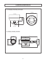
CAMERA INSTALLATION
jvuulj{Gwv~lyGjhislG
XUG~oluG|zpunGXYG}vs{zGkjGOGG\WWGhPG
wGpGaylk
jGaGORP
kjGXY}GwGz YUG~oluG|zpunGY[G}vs{zGhjGO[WG}GhP
ylkORP
hjGY[}
ishjraOTP
wGz ZUGjvuulj{G}pklvGjhislG
T jvuulj{GiujGjhislG{vG{olGiujGqhjrUG
[UGjvuulj{GhGGOy GP
T jGORGSGjvtPGGwGGGOTUGjvtPGG
uGGGlGhGkGGtG
kGG˄vu˅GGGU
R
wGhGkG
jvtG
hGvG
uGhGk
T
6
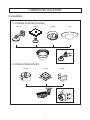
CAMERA INSTALLATION
Compatibility
1) HT7246IHR, HT7247IHR, HT7250IHR
INTWM
INTPM
CVCJBD
DFM
2) HTINTB8, HTINTB9, HTINTB10
CVCJBB
INTJBS
7
INTCM
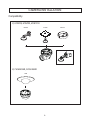
CAMERA INSTALLATION
Compatibility
3) HTINTD8, HTINTD9, HTINTD10
INTWM
INTPM
4) CVC6245IHR, CVC6246IHR
DFM
8
JB03TG
CAUTION : The installation instructions in this manual are for use by qualified service
personnel only. To reduce the risk of electric shock, do not perform any servicing other
than that contained in the operating instructions unless you are qualified to do so.
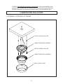
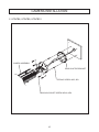
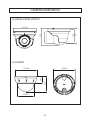
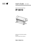
CAMERA INSTALLATION
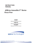
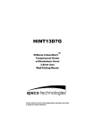
1. HT7246IHR / HT7247IHR / HT7250IHR
PLASTIC ANCHOR 6x30, 3EA
VANDAL DOME BASE ASSEMBLY
TAPPING SCREW 4X40, 3EA
VANDAL DOME BODY ASSEMBLY
BODY OUTER COVER
9
CAMERA INSTALLATION
2. HTINTB8, HTINTB9, HTINTB10
CAMERA ASSEMBLY
BASE ADAPTOR BRACKET
TAPPING SCREW 4X25, 4EA
HEXAGON SOCKET SCREW M5X10, 4EA
10
CAMERA INSTALLATION
3. HTINTD8, HTINTD9, HTINTD10
DOME BASE
TAPPING SCREW 4X25, 3EA
DOME ASSEMBLY
HEXAGON SOCKET SCREW M6X20, 2EA
DOME BODY
11
CAMERA INSTALLATION
4. HT647HRTP
BASE & ROTATE BRACKET ASSEMBLY
TAPPING SCREW 3X40, 3EA
BODY & DOME COVER ASSEMBLY
12
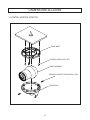
CAMERA INSTALLATION
5. CVC6245IHR, CVC6246IHR
BASE ASSEMBLY
TAPPING SCREW 4X20, 2EA
DOME COVER ASSEMBLY
13
650 Line Intensifier3
(Weatherproof Dome Camera with Chameleon™ Cover)
DC Auto Iris Varifocal Lens 2.8-12mm / 9-22mm / 5-50mm
■ HT7246IHR (2.8-12mm)
■ HT7247IHR (9-22mm)
■ HT7250IHR (5-50mm)
SPECIFICATIONS
MODEL
Image Pick-Up Device
TV System
Total Pixels
Effective Pixels
Scanning Frequency
Scanning System
Synchronization
Resolution
Minimum Illumination
S/N Ratio
Video Output
Electronic Shutter Speed
OSD
WDR
BLC
Day & Night
Gain Control
White Balance
Intensify
Motion Detection
Privacy Masking
SPECO DNR
Digital Zoom
DIS (Digital Image Stabilization)
Sharpness
Flip / Mirror
Power Supply
Power Consumption
Lens
Operational Temp.
Storage Temp.
Dimension
Weight
HT7246IHR / HT7247IHR / HT7250IHR
1/3” Sony Super HAD ll CCD
NTSC, PAL
NTSC=811(H) * 508(V) / PAL=795(H) * 596(V)
NTSC=768(H) * 494(V) / PAL=752(H) * 582(V)
NTSC=15.734KHz(H) & 59.94Hz(V) / PAL=15.625KHz(H) & 50.00Hz(V)
2:1 Interlace
Internal
650TV Lines
CDS OFF: 0.15 Lux, CDS ON: 0.00002 Lux
More than 52dB
CVBS: 1.0Vp-p / 75Ω
NTSC=(1/60sec~1/120,000sec) / PAL=(1/50sec~1/120,000sec)
Available
On / Off (Level adjustable)
BLC / HLC / OFF
Color / BW / AUTO
Low / High / Off
ATW / Outdoor / Indoor / Manual / AWC (1,700°K ~ 11,000°K)
Auto / Off (Selectable x2 ~ x512)
On / Off (8 Programmable Zones)
On / Off (12 Programmable Zones)
On / Off (Level adjustable)
On / Off (x1 ~ x16)
On / Off
On / Off (Level adjustable)
On / Off
DC 12V / AC24V(Dual Voltage)
DC 12V 250mA / AC24V 100mA
DC Auto Iris Varifocal Lens 2.8-12mm / 9-22mm / 5-50mm
-4ºF~140ºF RH 95% Max
-4ºF~140ºF RH 95% Max
5.10"(Dia) * 3.46"(H)
1 lbs
14
650 Line Intensifier3
(Weatherproof Bullet Camera with mount plate)
DC Auto Iris Varifocal Lens 2.8-12mm / 5-50mm / 9-22mm
■ HTINTB8 /
HTINTB8W
(2.8-12mm)
■ HTINTB9 /
■
HTINTB9W
(5-50mm)
HTINTB10 / HTINTB10W
(9-22mm)
SPECIFICATIONS
MODEL
Image Pick-Up Device
TV System
Total Pixels
Effective Pixels
Scanning Frequency
Scanning System
Synchronization
Resolution
Minimum Illumination
S/N Ratio
Video Output
Electronic Shutter Speed
OSD
WDR
BLC
Day & Night
Gain Control
White Balance
Intensify
Motion Detection
Privacy Masking
SPECO DNR
Digital Zoom
DIS (Digital Image Stabilization)
Sharpness
Flip / Mirror
Power Supply
Power Consumption
Lens
Operational Temp.
Storage Temp.
Dimension
Weight
HTINTB8 / HTINTB9 / HTINTB10
1/3” Sony Super HAD ll CCD
NTSC, PAL
NTSC=811(H) * 508(V) / PAL=795(H) * 596(V)
NTSC=768(H) * 494(V) / PAL=752(H) * 582(V)
NTSC=15.734KHz(H) & 59.94Hz(V) / PAL=15.625KHz(H) & 50.00Hz(V)
2:1 Interlace
Internal
650TV Lines
CDS OFF: 0.15 Lux, CDS ON: 0.00002 Lux
More than 52dB
CVBS: 1.0Vp-p / 75Ω
NTSC=(1/60sec~1/120,000sec) / PAL=(1/50sec~1/120,000sec)
Available
On / Off (Level adjustable)
BLC / HLC / OFF
Color / BW / AUTO
Low / High / Off
ATW / Outdoor / Indoor / Manual / AWC (1,700°K ~ 11,000°K)
Auto / Off (Selectable x2 ~ x512)
On / Off (8 Programmable Zones)
On / Off (12 Programmable Zones)
On / Off (Level adjustable)
On / Off (x1 ~ x16)
On / Off
On / Off (Level adjustable)
On / Off
DC 12V / AC24V(Dual Voltage)
DC 12V 400mA / AC24V 170mA
DC Auto Iris Varifocal Lens 2.8-12mm / 5-50mm / 9-22mm
-4ºF~140ºF RH 95% Max
-4ºF~140ºF RH 95% Max
3.46"(W) * 4.01"(H) * 11.02"(D)
3 lbs
15
650 Line Intensifier3
(Weatherproof Dome Camera)
DC Auto Iris Varifocal Lens 2.8-12mm / 5-50mm / 9-22mm
■ HTINTD8 /
HTINTD8W
(2.8-12mm)
■ HTINTD9 /
■
HTINTD9W
(5-50mm)
HTINTD10 / HTINTD10W
(9-22mm)
SPECIFICATIONS
MODEL
Image Pick-Up Device
TV System
Total Pixels
Effective Pixels
Scanning Frequency
Scanning System
Synchronization
Resolution
Minimum Illumination
S/N Ratio
Video Output
Electronic Shutter Speed
OSD
WDR
BLC
Day & Night
Gain Control
White Balance
Intensify
Motion Detection
Privacy Masking
SPECO DNR
Digital Zoom
DIS (Digital Image Stabilization)
Sharpness
Flip / Mirror
Power Supply
Power Consumption
Lens
Operational Temp.
Storage Temp.
Dimension
Weight
HTINTD8 / HTINTD9 / HTINTD10
1/3” Sony Super HAD ll CCD
NTSC, PAL
NTSC=811(H) * 508(V) / PAL=795(H) * 596(V)
NTSC=768(H) * 494(V) / PAL=752(H) * 582(V)
NTSC=15.734KHz(H) & 59.94Hz(V) / PAL=15.625KHz(H) & 50.00Hz(V)
2:1 Interlace
Internal
650TV Lines
CDS OFF: 0.15 Lux, CDS ON: 0.00002 Lux
More than 52dB
CVBS: 1.0Vp-p / 75Ω
NTSC=(1/60sec~1/120,000sec) / PAL=(1/50sec~1/120,000sec)
Available
On / Off (Level adjustable)
BLC / HLC / OFF
Color / BW / AUTO
Low / High / Off
ATW / Outdoor / Indoor / Manual / AWC (1,700°K ~ 11,000°K)
Auto / Off (Selectable x2 ~ x512)
On / Off (8 Programmable Zones)
On / Off (12 Programmable Zones)
On / Off (Level adjustable)
On / Off (x1 ~ x16)
On / Off
On / Off (Level adjustable)
On / Off
DC 12V / AC24V(Dual Voltage)
DC 12V 400mA / AC24V 170mA
DC Auto Iris Varifocal Lens 2.8-12mm / 5-50mm / 9-22mm
-4ºF~140ºF RH 95% Max
-4ºF~140ºF RH 95% Max
5.47"(Dia) * 4.36"(H)
3.08 lbs
16
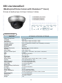
650 Line Intensifier3
(Miniature Weatherproof Dome Camera with Chameleon™ Cover)
3.6mm Fixed Board Lens
■ HT647HRTP (3.6 Fixed Board Lens)
SPECIFICATIONS
HT647HRTP
MODEL
Image Pick-Up Device
TV System
Total Pixels
Effective Pixels
Scanning Frequency
Scanning System
Synchronization
Resolution
Minimum Illumination
S/N Ratio
Video Output
Electronic Shutter Speed
OSD
WDR
BLC
Day & Night
Gain Control
White Balance
Intensify
Motion Detection
Privacy Masking
SPECO DNR
Digital Zoom
DIS (Digital Image Stabilization)
Sharpness
Flip / Mirror
Power Supply
Power Consumption
Lens
Operational Temp.
Storage Temp.
Dimension
Weight
1/3” Sony Super HAD ll CCD
NTSC, PAL
NTSC=811(H) * 508(V) / PAL=795(H) * 596(V)
NTSC=768(H) * 494(V) / PAL=752(H) * 582(V)
NTSC=15.734KHz(H) & 59.94Hz(V) / PAL=15.625KHz(H) & 50.00Hz(V)
2:1 Interlace
Internal
650TV Lines
CDS OFF: 0.15 Lux, CDS ON: 0.00002 Lux
More than 52dB
CVBS: 1.0Vp-p / 75Ω
NTSC=(1/60sec~1/120,000sec) / PAL=(1/50sec~1/120,000sec)
Available
On / Off (Level adjustable)
BLC / HLC / OFF
Color / BW / AUTO
Low / High / Off
ATW / Outdoor / Indoor / Manual / AWC (1,700°K ~ 11,000°K)
Auto / Off (Selectable x2 ~ x512)
On / Off (8 Programmable Zones)
On / Off (12 Programmable Zones)
On / Off (Level adjustable)
On / Off (x1 ~ x16)
On / Off
On / Off (Level adjustable)
On / Off
DC 12V
DC 12V 250mA
3.6mm Fixed Board Lens
-4ºF~140ºF RH 95% Max
-4ºF~140ºF RH 95% Max
4.33"(Dia) * 3.14"(H)
1.54 lbs
17
650 Line Intensifier3
(Indoor Wall & Ceiling Mount Dome Camera)
DC Auto Iris Varifocal Lens 2.8-12mm
■ CVC6245IHR /
CVC6245IHRW
(2.8-12mm)
SPECIFICATIONS
MODEL
Image Pick-Up Device
TV System
Total Pixels
Effective Pixels
Scanning Frequency
Scanning System
Synchronization
Resolution
Minimum Illumination
S/N Ratio
Video Output
Electronic Shutter Speed
OSD
WDR
BLC
Day & Night
Gain Control
White Balance
Intensify
Motion Detection
Privacy Masking
SPECO DNR
Digital Zoom
DIS (Digital Image Stabilization)
Sharpness
Flip / Mirror
Power Supply
Power Consumption
Lens
Operational Temp.
Storage Temp.
Dimension
Weight
CVC6245IHR / CVC6245IHRW
1/3” Sony Super HAD ll CCD
NTSC, PAL
NTSC=811(H) * 508(V) / PAL=795(H) * 596(V)
NTSC=768(H) * 494(V) / PAL=752(H) * 582(V)
NTSC=15.734KHz(H) & 59.94Hz(V) / PAL=15.625KHz(H) & 50.00Hz(V)
2:1 Interlace
Internal
650TV Lines
CDS OFF: 0.15 Lux, CDS ON: 0.00002 Lux
More than 52dB
CVBS: 1.0Vp-p / 75Ω
NTSC=(1/60sec~1/120,000sec) / PAL=(1/50sec~1/120,000sec)
Available
On / Off (Level adjustable)
BLC / HLC / OFF
Color / BW / AUTO
Low / High / Off
ATW / Outdoor / Indoor / Manual / AWC (1,700°K ~ 11,000°K)
Auto / Off (Selectable x2 ~ x512)
On / Off (8 Programmable Zones)
On / Off (12 Programmable Zones)
On / Off (Level adjustable)
On / Off (x1 ~ x16)
On / Off
On / Off (Level adjustable)
On / Off
DC 12V
DC 12V 250mA
DC Auto Iris Varifocal Lens(2.8mm-12mm)
-4ºF~140ºF RH 95% Max
-4ºF~140ºF RH 95% Max
5.51"(Dia) * 4.09"(H)
1.54 lbs
18
650 Line Intensifier3
(Indoor Wall & Ceiling Mount Dome Camera)
DC Auto Iris Varifocal Lens 2.8-12mm
■ CVC6246IHR /
CVC6246IHRW
(2.8-12mm)
SPECIFICATIONS
MODEL
Image Pick-Up Device
TV System
Total Pixels
Effective Pixels
Scanning Frequency
Scanning System
Synchronization
Resolution
Minimum Illumination
S/N Ratio
Video Output
Electronic Shutter Speed
OSD
WDR
BLC
Day & Night
Gain Control
White Balance
Intensify
Motion Detection
Privacy Masking
SPECO DNR
Digital Zoom
DIS (Digital Image Stabilization)
Sharpness
Flip / Mirror
Power Supply
Power Consumption
Lens
Operational Temp.
Storage Temp.
Dimension
Weight
CVC6246IHR / CVC6246IHRW
1/3” Sony Super HAD ll CCD
NTSC, PAL
NTSC=811(H) * 508(V) / PAL=795(H) * 596(V)
NTSC=768(H) * 494(V) / PAL=752(H) * 582(V)
NTSC=15.734KHz(H) & 59.94Hz(V) / PAL=15.625KHz(H) & 50.00Hz(V)
2:1 Interlace
Internal
650TV Lines
CDS OFF: 0.15 Lux, CDS ON: 0.00002 Lux
More than 52dB
CVBS: 1.0Vp-p / 75Ω
NTSC=(1/60sec~1/120,000sec) / PAL=(1/50sec~1/120,000sec)
Available
On / Off (Level adjustable)
BLC / HLC / OFF
Color / BW / AUTO
Low / High / Off
ATW / Outdoor / Indoor / Manual / AWC (1,700°K ~ 11,000°K)
Auto / Off (Selectable x2 ~ x512)
On / Off (8 Programmable Zones)
On / Off (12 Programmable Zones)
On / Off (Level adjustable)
On / Off (x1 ~ x16)
On / Off
On / Off (Level adjustable)
On / Off
DC 12V / AC24V(Dual Voltage)
DC 12V 250mA / AC24V 100mA
DC Auto Iris Varifocal Lens(2.8mm-12mm)
-4ºF~140ºF RH 95% Max
-4ºF~140ºF RH 95% Max
5.51"(Dia) * 4.09"(H)
1.54 lbs
19
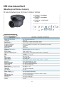
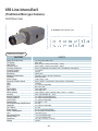
650 Line Intensifier3
(Traditional Box type Camera)
C&CS Mount Lens
■ HTINTT5 (C&CS Mount Lens)
SPECIFICATIONS
HTINTT5
MODEL
Image Pick-Up Device
TV System
Total Pixels
Effective Pixels
Scanning Frequency
Scanning System
Synchronization
Resolution
Minimum Illumination
S/N Ratio
Video Output
Electronic Shutter Speed
OSD
WDR
BLC
Day & Night
Gain Control
White Balance
Intensify
Motion Detection
Privacy Masking
SPECO DNR
Digital Zoom
DIS (Digital Image Stabilization)
Sharpness
Flip / Mirror
Power Supply
Power Consumption
Lens
Operational Temp.
Storage Temp.
Dimension
Weight
1/3” Sony Super HAD ll CCD
NTSC, PAL
NTSC=811(H) * 508(V) / PAL=795(H) * 596(V)
NTSC=768(H) * 494(V) / PAL=752(H) * 582(V)
NTSC=15.734KHz(H) & 59.94Hz(V) / PAL=15.625KHz(H) & 50.00Hz(V)
2:1 Interlace
Internal
650TV Lines
CDS OFF: 0.15 Lux, CDS ON: 0.00002 Lux
More than 52dB
CVBS: 1.0Vp-p / 75Ω
NTSC=(1/60sec~1/120,000sec) / PAL=(1/50sec~1/120,000sec)
Available
On / Off (Level adjustable)
BLC / HLC / OFF
Color / BW / AUTO
Low / High / Off
ATW / Outdoor / Indoor / Manual / AWC (1,700°K ~ 11,000°K)
Auto / Off (Selectable x2 ~ x512)
On / Off (8 Programmable Zones)
On / Off (12 Programmable Zones)
On / Off (Level adjustable)
On / Off (x1 ~ x16)
On / Off
On / Off (Level adjustable)
On / Off
DC 12V / AC24V(Dual Voltage)
DC 12V 250mA / AC24V 100mA
C&CS Mount Lens
-4ºF~140ºF RH 95% Max
-4ºF~140ºF RH 95% Max
2.51"(W) * 2.20"(H) * 3.46"(D)
0.88 lbs
20
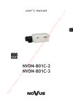
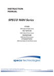
CAMERA DIMENSION
1) HT7246IHR, HT7247IHR, HT7250IHR
5.10” dia
3.46”
1.16”
5.10” dia
3.93” dia
2) HTINTB8, HTINTB9, HTINTB10
11.02”
3.46”
3.89” dia
3.11”
4.01”
5.90”
5.03”
10.51”
21
CAMERA DIMENSION
3) HTINTD8, HTINTD9, HTINTD10
4) HT647HRTP
4.33” dia
3.14”
1.41”
4.33” dia
3.22” dia
22
3.70”
4.36”
3.34”
5.47” dia
CAMERA DIMENSION
5) CVC6245IHR, CVC6246IHR
5.51” dia
4.09”
1.25”
5.51” dia
4.60” dia
6) HTINTT5
3.46”
3.26”
1.49” dia
2.20”
2.51”
23
FEATURES
Now with “PRESETS”
PRESETS (Outdoor, Indoor, Elevator, Lobby, Hallway & Low Light)
Used for a quick and easy setup for the installation environment.
650TVL Resolution
Horizontal resolution of 650 TV lines is achieved by using a
SONY Super-HAD CCD with 410,000 pixels, and a custom DSP
yielding pictures with a high S/N ratio.
INTENSIFIER 3
More Powerful Performance in low light condition.
High quality Pictures to be captured in very low light condition.
WDR
More Powerful WDR in strong back lighting.
Your camera allows you to get a clear image.
SPECO DNR
The Intensifier camera has a DSP chip that can remove image
noise efficiently showing clean images in low light conditions.
HLC (High Light Compensation)
This function reverses bright spots in the picture (such as
headlights). This enables the entire system to do a better job of
resolving and displaying grayscale information such as a
license plate.
24
FEATURES
Motion Detection with Alarm Output
Built in motion detector with adjustable areas of coverage will
Send a signal to an external alarm device when motion is detected.
Privacy Mask
It also has the ability to mask up to 8 areas of the picture where
Viewing is not desired. Each zone can be independently
programmed via the OSD
Stabilizer
This function removes image jitter that is caused by vibrations in
the building and reduces the amount of hard drive space.
Digital Zoom
The picture could be enlarged by this function in digital.
Day/Night
The Intensifier camera can show color pictures in all lighting
conditions, or you can have it automatically swiches to a B/W
picture in low light conditions
OSD
All camera functions are menu driven for easy use.
25
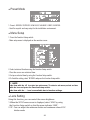
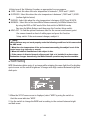
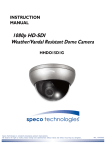
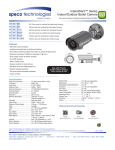
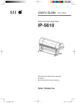
●
Preset Mode
SPECO TECH
1.PRESET MODE
2.MAIN SETUP
3.EXIT
INDOOR
RESET
1. Preset : INDOOR / OUTDOOR / LOW LIGHT / HALLWAY / LOBBY / ELEVATOR.
- Used for a quick and easy setup for the installation environment.
●
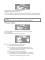
Menu Setup
1. Press the Function Setup switch.
- Main setup menu is displayed on the monitor screen.
MAIN SETUP
1.LENS
2.EXPOSURE
3.WHITE BAL
4.WDR
5.BACKLIGHT
6.SPECO DNR
7.DAY/NIGHT
8.SPECIAL
9.RETURN
DC
ATW
OFF
OFF
ON
AUTO
SAVE
2. Select a desired function using the Function Setup switch.
- Place the cursor over a desired item.
3. Set up a selected item by using the Function Setup switch.
4. To finish the setting, select 'RETURN' and press the Function Setup switch.
☞ NOTE
■ An item with the ◀ icon also has sub menus. To select a sub menu, select an item
with the icon and press the Function Setup switch.
■ An item with the - - - icon is unavailable due to function settings.
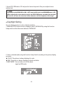
●
Lens Setting
Using this function, you can control the screen brightness.
1. When the SETUP menu screen is displayed, select 'LENS' by using
the Function Setup switch so that the arrow indicates 'LENS'.
2. DC : You can adjust the minimum shutter and maximum value of ESC
shutter mode.
26
MAIN SETUP
1.LENS
2.EXPOSURE
3.WHITE BAL
DC
ATW
3. THE Lens mode has sub menu items as listed below.
- BRIGHTNESS : Adjusts the video brightness.
- FOCUS ADJ : To adjust the DC lens focus correctly, you must activate the Focus Settings mode under each
lens menu. Activate the Focus Settings mode, adjust the lens focus, and then deactivate the settings mode.
☞ NOTE
■ If color rolling occurs when using a DC lens, set Shutter to Fixed (---).
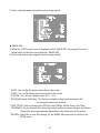
●
Exposure Setting
MAIN SETUP
1.LENS
2.EXPOSURE
3.WHITE BAL
DC
ATW
1. When the SETUP menu screen is displayed, select 'EXPOSURE' by using the Function Setup Switch.
2. Select a desired mode using the Function Setup switch.
EXPOSURE SETUP
1.BRIGHTNESS
2.SHUTTER
3.AGC
4.INTENSIFY
5.RETURN
25
--HIGH
OFF
◆ SHUTTER : You can select either auto or manual shutter.
* --- : Shutter speed is fixed at 1/60sec(1/50sec)
* ESC : Select this to control the shutter speed automatically. If ESC is
selected, the shutter speed is automatically controlled depending
on the ambient illumination of the subject.
* MANUAL : You can control shutter speed manually.
(NTSC MODEL : 1/60~1/120,000, PAL MODEL : 1/50~1/120,000)
* A.FLK : Select this when you see picture flicker, this can happen when the
frequency of the local lighting clashes with the camera.
27
☞ NOTE
■ When the SHUTTER is set to MANUAL or A.FLK mode, INTENSIFY will be disabled.
◆ FUTO GAIN CONTROL) : The higher the gain level, the brighter the screen
- but the higher the noise.
* OFF : Deactivates the AGC function.
* LOW : Allows automatic gain control from 5.3dB to 32dB.
* HIGH : Allows automatic gain control from 5.3dB to 37dB.
◆ INTENSIFY : When it is night or dark, the camera automatically detects the
light level and maintains a clear picture if this mode is activated.
* OFF : Deactivates the INTENSIFY function.
* AUTO : Activates the INTENSIFY function.
◆ RETURN : Select this to save the changes in the EXPOSURE menu and return
to the SETUP menu.
☞ NOTE
■ If you press the Function Setup switch to ‘AUTO’ mode, you can adjust brightness by
increasing or decreasing the shutter speed. (x2 ~ x512)
■ Note that the higher the zoom level, the brighter the screen, but the more likely there
will be a ghosting effect.
■ It is normal for Noise, Spots and Whitish symptoms to appear in INTENSIFY mode
when the D-ZOOM level is increased.
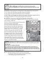
●
White Balance (White Bal) Setting
Use the White Balance function to adjust the screen color.
1. When the SETUP menu screen is displayed, select 'White Bal' by using the Function
Setup switch so that the arrow indicates 'White Bal'.
2. Select a desired mode using the Function Setup switch.
MAIN SETUP
1.LENS
2.EXPOSURE
3.WHITE BAL
28
DC
ATW
※Select one of the following 5 modes, as appropriate for your purpose.
◆ ATW : Select this when the color temperature is between 1,700˚K and 11,000˚K.
◆ OUTDOOR : Select this when the color temperature is between 1,700˚K and 11,000˚K.
(sodium light inclusion)
◆ INDOOR : Select this when the color temperature is between 4,500˚K and 8,500˚K.
◆ MANUAL : Select this to fine-tune White Balance manually. Set White Balance first
by using the ATW or AWC mode. After that switch to MANUAL mode,
fine-tune the White Balance and then press the Function Setup switch.
◆ AWC→SET : To find the optimal luminance level for the current environment, point
the camera towards a sheet of white paper and press the Function
Setup switch. If the environment changes, readjust it.
☞ NOTE
■ White Balance may not work properly under the following conditions. In this case select
the AWC mode.
① When the color temperature of the environment surrounding the subject is out of the
control range (e.g. clear sky or sunset).
② When the ambient illumination of the subject is dim.
③ If the camera is directed towards a fluorescent light or is installed in a place where
illumination changes dramatically, the White Balance operation may become unstable.
●
WDR Setting
WDR illuminates darker spots of an image while retaining the same light level for brighter
spots to even out the overall brightness of images with high contrast between bright and
dark spots.
MAIN SETUP
1.LENS
2.EXPOSURE
3.WHITE BAL
4.WDR
DC
ATW
OFF
1. When the SETUP menu screen is displayed, select 'WDR' by using the switch so that the arrow indicates 'WDR'.
2. Use the switch to change the WDR level according to the contrast between bright and dark areas.
29
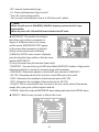
●
Backlight Setting
Unlike conventional cameras, the 650Line Intensifier3™ Series are designed to deliver a
distinctive subject and background at the same time, even when the subject is backlight,
by using the features of the proprietary W-V DSP chip.
1. When the SETUP menu screen is displayed, select 'BACKLIGHT' by using the Function
Setup switch so that the arrow indicates 'BACKLIGHT'.
MAIN SETUP
1.LENS
2.EXPOSURE
3.WHITE BAL
4.WDR
5.BACKLIGHT
6.SPECO DNR
7.DAY/NIGHT
8.SPECIAL
9.RETURN
DC
ATW
OFF
OFF
ON
AUTO
SAVE
2. Select a desired mode using the Function Setup switch.
◆ BLC : Enables a user to directly select a desired area from a picture, and to view
the area more clearly.
◆ HLC (High Light Compensation) : If the scene contains extremely bright light areas
such as; from car headlights, the light can mask out much of the on-screen detail
- LEVEL : Adjust level of the HLC function.
- LIMIT : Enable to change the operating condition.
- MASK COLOR/TONE : Change the color / transparency of the masking area.
(Black, Red, Blue, Cyan, Magenta)
- TOP/BOTTOM/LEFT/RIGHT : Adjust the area to be enhanced
◆ OFF : Not being used
3. Select a desired mode using the Function Setup switch and press the Function Setup
switch.
u Select 'BLC' to adjust the area to be enhanced then adjust the level.
30
BLC SETUP
LEVEL
TOP
BOTTOM
LEFT
RIGHT
HLC SETUP
LOW
38
109
54
121
LEVEL
MIDDLE
LIMITS
NIGHT ONLY
MASK COLOR
BLACK
MASK TONE
1
TOP
5
BOTTOM
120
LEFT
5
RIGHT
172
Press Set to Return
Press Set to Return
☞ NOTE
■ Because there can be a difference in the effectiveness of HLC according to the amount
of light area in the screen, optimize the installation angle for the best HLC performance.
■ When dark, the HLC is only activated when a bright light exceeding a specific size in
NIGHT ONLY mode.
■ The HLC is not activated in day light or when bright light is not present at night in NIGHT
ONLY mode.
■ BLC Function doesn't work in the B/W mode of the DAY/NIGHT menu.
●
SPECO DNR Setting
This function reduces the background noise in a low luminance environment.
1. When the SETUP menu screen is displayed, select 'SPECO DNR' by using the Function Setup switch so that
the arrow indicates 'SPECO DNR'.
MAIN SETUP
1.LENS
2.EXPOSURE
3.WHITE BAL
4.WDR
5.BACKLIGHT
6.SPECO DNR
7.DAY/NIGHT
8.SPECIAL
9.RETURN
2. Select a desired mode using the Function Setup switch.
◆ OFF : Deactivates SPECO DNR. Noise is not reduced.
◆ ON : Activates SPECO DNR so that noise is reduced.
31
DC
ATW
OFF
OFF
ON
AUTO
SAVE
3. Set the SPECO DNR mode to 'ON' and press the Function Setup switch. Then you can adjust the noise
reduction level.
☞ NOTE
■ You cannot set the SPECO DNR to ‘ON’ or ‘OFF’ when the AGC mode of the EXPOSURE menu is ‘OFF’.
■ When adjusting the noise reduction level in the SPECO DNR mode, remember that the higher
the level set, the more the noise level will be reduced, as will the brightness of the image.
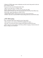
●
Day/Night Setting
You can display pictures in color or black and white.
1. When the SETUP menu screen is displayed, select 'DAY/NIGHT'by using the Function
Setup switch so that the arrow indicates 'DAY/NIGHT'.
MAIN SETUP
1.LENS
2.EXPOSURE
3.WHITE BAL
4.WDR
5.BACKLIGHT
6.SPECO DNR
7.DAY/NIGHT
8.SPECIAL
9.RETURN
DC
ATW
OFF
OFF
ON
AUTO
SAVE
2. Select a desired mode using the Function Setup Switch according to the picture display
you want.
◆ COLOR : The picture is always displayed in color.
◆ B/W : The picture is always displayed in black and white.
- BURST MODE : You can turn on or off the burst
signal on B/W mode.
B/W MODE SETUP
1.BURST MODE
2.RETURN
32
OFF
◆ AUTO : The mode is switched to 'Color' in a normal environment, but switches to 'B/W'
mode when ambient illumination is low. To set up the switching time for AUTO mode, press
the Function Setup switch. You can turn on or off the burst signal on B/W mode.
- BURST MODE : You can turn on or off the burst signal
AUTO SETUP
on B/W mode.
1.BURST MODE
ON
- DURATION : You can select brightness of illumination
2.COLOR→B/W
about changing the day/night mode.
DURATION
FAST
- DWELLTIME : You can select the duration time about
DWELL TIME
3SEC
changing the day/night mode.
3.B/W→COLOR
DURATION
FAST
g3s, 5s, 7s, 10s, 15s, 20s, 30s, 40, 60s
DWELL TIME
4.RETURN
FAST
SLOW
COLOR→B/W
2.5 lux
1 lux
B/W→COLOR
5 lux
10 lux
10SEC
* The day/night switching point of the
camera can be adjusted.
☞ NOTE
■ When AGC in the EXPOSURE menu is 'OFF', '---' mode operates as like selecting 'COLOR'
mode and 'AUTO' mode can not be selected.
●
Special Setting
1. When the SETUP menu screen is displayed, select 'SPECIAL' by using the Function Setup switch so that the arrow indicates 'SPECIAL'.
MAIN SETUP
1.LENS
2.EXPOSURE
3.WHITE BAL
4.WDR
5.BACKLIGHT
6.SPECO DNR
7.DAY/NIGHT
8.SPECIAL
9.RETURN
33
DC
ATW
OFF
OFF
ON
AUTO
SAVE
2. Select a desired mode using the Function Setup switch.
SPECIAL
1.IMAGE ADJ
2.MONITOR
3.CAM TITLE
4.SYNC
5.MOTION DET
6.PRIVACY
7.COMM ADJ
8.LANGUAGE
9.RETURN
OFF
INT
OFF
OFF
ENGLISH
◆ IMAGE ADJ. :
1) When the SETUP menu screen is displayed, select 'IMAGE ADJ' by using the Function Setup switch so that the arrow indicates 'IMAGE ADJ'.
2) Select a desired mode using the Function Setup switch.
IMAGE SETUP
1.V-REV
2.H-REV
3.D-ZOOM
4.DIS
5.FONT COLOR
6.SHARPNESS
7.RETURN
OFF
OFF
WHITE
ON
* V-REV : You can flip the picture vertically on the screen.
* H-REV : You can flip the picture horizontally on the screen.
* D-ZOOM : You can use a digital zoom of x1 ~ x16.
* DIS (Digital Image Stabilizer) : This function mitigates any picture movement due
to external factors such as wind.
* FONT COLOR : You can change the OSD font color. (White, Yellow, Green, Red, Blue)
* SHARPNESS : As you increase this value, the picture outline becomes stronger and clearer.
Adjust this value appropriately depending on the sharpness of the picture.
* RETURN : Select this to save the settings for the IMAGE ADJ menu and to return to the SETUP menu.
34
☞ NOTE
■ When the V-REV or H-REV mode is enabled, the text on the screen does not flip.
■ If you increase the SHARPNESS level too high, the picture may become distorted or noise
may appear.
◆ MONITOR : Please change the settings value of video appropriate to your monitor.
1) LCD : Please select this menu item when using a LCD monitor.
2) CRT : Please select this menu item when using a CRT monitor.
3) USER : Please use this menu item when using a monitor other than standard ones. You
can change the gamma, PED level, and color gain in the sub menus.
◆ CAM TITLE : If you enter a title, the title will appear on the monitor.
1) If the SPECIAL menu screen is displayed, use the Function Setup switch so that the
arrow indicates 'CAM TITLE'.
CAMERA TITLE SETUP
2) Set it to 'ON' by using the Function Setup switch.
ABCDEFGHIJKLM
3) Press the Function Setup switch.
NOPQRSTUVWXYZ
4) Use the Function Setup switch to move to a
a b c d e f g h i j k l m
n o p q r s t u v w x y z
desired letter and select the letter by pressing
- . 0 1 2 3 4 5 6 7 8 9
the Function Setup switch. Repeat this to enter
←→CLR
POS
END
multiple letters. You can enter up to 15 letters.
5) Enter a title, move the cursor to 'POS' and
SHOP
press the Function Setup switch. The entered
title appears on the screen. Select the position
to display the title on the screen by using the
Function Setup switch and press the Function
Setup switch. When the position is determined,
select 'END' and press the Function Setup switch
to return to the SPECIAL menu.
☞ NOTE
■ When the CAM TITLE menu is ‘OFF’, no title will be displayed on the monitor screen even if
you enter one.
■ Only English is available in this mode.
■ If you move the cursor to CLR and press the Function Setup switch, all the letters are
deleted. To edit a letter, change the cursor to the bottom left arrow and press the Function
Setup switch. Move the cursor over the letter to be edited, move the cursor to the letter to be
inserted and then press the Function Setup switch.
◆ SYNC : In areas where the supply is at 60Hz(NTSC), 50Hz(PAL), you can synchronize
the output phase of multiple cameras using the power synchronization function
(Line-Lock) without using a synchronization signal generator.
35
- INT : Internal Synchronization Type
- L/L : Power Synchronization Type, Line-lock
* Press the Function Setup switch.
* You can select a desired phase from 0 to 359 when select 'phase'.
☞ NOTE
■ When using AC power at 60Hz(NTSC), 50Hz(PAL), frequency, you can use the L/L type
synchronization.
■ When the power is DC 12V, the SYNC menu is fixed to the ‘INT’ mode.
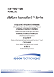
◆ MOTION DET :This product has a feature
MOTION DET
that allows you to observe movement of
1.SENSITIVITY
AREA1
objects in 8 different areas on the screen,
2.AREA MODE
ON
3.SEL POS
L-TOP
and the words 'MOTION DETECTED' appear
4.XPOS
3
on the screen when movement is detected.
5.YPOS
5
Activity can be monitor more efficiently.
6.FILL → SET
7.RETRUN
1) When the SPECIAL menu screen is displayed,
press the Function Setup switch so that the arrow
indicates‘MOTION DET’.
2) Set up the mode using the Function Setup switch.
- SENSITIVITY : You can select up to 8 MD areas. When SENSITIVITY number is high, motion
detection sensitivity is increased to recognize even small movement.
- AREA MODE : Determines whether to use the MD area selected in SENSITIVITY.
- SEL POS : Determines which of the 4 vertices of each MD area is to be used.
- XPOS : Determines the coordinate of the horizontal axis for SEL POS.
- YPOS : Determines the coordinate of the vertical axis for SEL POS.
- FILLgSET : Fills in a selected MD area. The color of the area can be selected from brown,
orange, blue, cyan, green, yellow, magenta and red.
- RETURN : Select this to save the MOTION DET menu settings and return to the SPECIAL menu.
◆ PRIVACY : Mask an area you want to hide on the screen.
PRIVACY AREA SETUP
1.AREA
2.MODE
3.MASK COLOR
4.MASK TONE
5.TOP
6.BOTTOM
7.LEFT
8.RIGHT
9.RETURN
AREA1
OFF
GREEN
1
39
79
13
52
36
1) When the SPECIAL menu screen is displayed, press the Function Setup switch so that the
arrow indicates 'PRIVACY'.
2) Set up the mode using the Function Setup switch.
- AREA : You can select up to 12 PRIVACY areas.
- MODE : Determines whether to use the area selected in the AREA.
- MASK COLOR : Determine area color. You can select Green, Red, Blue, Black, White, Gray.
- MASK TONE : Adjust the brightness of MASK COLOR.
- TOP/BOTTOM/LEFT/RIGHT :Adjust the size and position of the selected area.
- RETURN : Select this to save the PRIVACY menu settings and return to the SPECIAL menu.
●
RETURN Setting
Select a desired RETURN mode using the Function Setup Switch.
- SAVE : Save the current settings and RETURN the MAIN SETUP menu.
- NOT SAVE : Do not save the current settings and RETURN the MAIN SETUP menu.
- RESET : Resets the camera settings to the factory defaults. Language, Communication and
Monitor Settings are not initialized.
37
●
Trouble Shooting
PROBLEM
Northing appears on
the screen.
POSSIBLE CAUSE
FCheck the power cable, power supply output and video
connection between the camera and monitor.
FAre the camera lens or the lens glass dirty?
The image on the
screen is dim.
Clean the lens / glass with a soft clean cloth.
FAdjust the monitor controls, as required.
FIf the camera is facing a very strong light, change
the camera position.
FAdjust the lens focus.
The image on the
screen is dark.
FAdjust the contrast control of the monitor.
The camera is not
working properly
and the surface of
the camera is hot.
FCheck the camera is correctly connected to an appropriate
Motion Detection
is not activated.
FHas MOTION DET been set to ON in the menu?
The color of the
picture is not correct.
FIf there is an intermediate device, correctly set the 75Ω/Hi-z.
regulated power source.
FHas MD AREA been properly defined?
FCheck the settings in WHITE BALANCE menu.
The image on the
screen flickers.
FMake sure that the camera isn’t facing direct sunlight or
The INTENSIFY does
not work.
FCheck that the AGC setting in the EXPOSURE menu is’t set to OFF.
fluorescent lighting. If necessary,change the camera position.
FCheck the EXPOSURE menu and make sure SHUTTER is set to------.
38
39
uMEMO
40
uMEMO
41
uMEMO
42
200 New Highway
Amityville, NY 11701
631-957-8700
1 800 645 5516
www.specotech.com