1
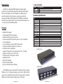
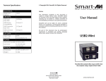
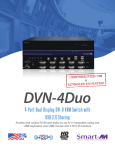
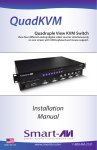
Installation
Manual
DVR4X4
4-port DVI-D Matrix Switch
with RS-232, IR, USB and TCP/IP Control (optional)
Display Content From Any 4 Computers On Any
4 Screens Independently Up To 30 Feet Away
www.smartavi.com
Introduction
What’s in the Box?
SmartAVI’s non-blocking DVR4X4 digital video matrix switch
provides an easy and dynamic approach to switching the DVI output
from up to 4 computers, to up to 4 displays. The switching can be
controlled directly via the front panel, or remotely using RS-232
commands, IR, USB or TCP/IP (optional). The DVR4X4 is controlled by
Windows®-based software that is easy to understand and simple to use
– a cornerstone of all SmartAVI products.
Features
•
•
•
•
•
•
•
•
•
•
•
•
•
•
Multiple EDID Support
Programmable EDID from computer
Automatic EDID learning from monitor
Increases productivity by providing access to up to 4 computers
from 4 workstations.
4 x 4 non-blocking, single-link DVI-D matrix switch
Automatic output pre-emphasis and drive level
Automatic receiver equalization
Supports DVI operation at the maximum rate of 2 x 1.65 Gbps
Supports resolutions up to 1920 x 1200
Control from either front panel or RS-232
Available IR remote
USB Control Available
Ethernet control available
Easy-to-use Windows based software
PART NO.
DVR4X4S
User Manual
QTY DESCRIPTION
1
DVI-D 4X4 Router. Includes: [DVR4X4 & PS5VD4A]
1
Technical Specifications
VIDEO
Format
DVI-D Single Line
Maximum Pixel Clock
165 MHz
Input Interface
(4) DVI-I 29-pin female
Output Interface
(4) DVI-I 29-pin female
Resolution
Up to 1920 x 1200
DDC
5 volts p-p(TTL)
Input Equalization
Automatic
Input Cable Length
Up to 30 ft.
Output Cable Length
Up to 30 ft.
OTHER
Control
RS-232, IR, USB and TCP/IP via SMTCP
Power
External 5VDC4A
Dimensions
12”W x 1.7”H (1U) x 6.5”D
Weight
4.05 lbs.
Approvals
UL, CE, ROHS Compliant
RK-DVR-4X4 Front
RK-DVR-4X4 Rear
The DVR4X4 provides single-link, DVI-D operation at the maximum
TMDS rate of 2 x 1.65 Gbps at resolutions up to 1920 x 1200. The DVI-D
signals can be transmitted through 30 feet of copper at the maximum
TMDS rate on both the input and output sides of the switch.
2
www.smartavi.com
www.smartavi.com
3
Installation
COMPUTERS
DVI-D DISPLAYS
30 ft. over DVI-D
30 ft. over DVI-D
Connecting the DVR4X4
1. Power off the computers and displays.
2. Connect the DVI video cables from the computers to the DVI-D inputs on the rear of the
DVR4X4.
3. Connect the DVI displays to the DVI-D outputs on the rear of the DVR4X4.
4. Power on the DVR4X4.
5. Power on the computers and displays.
DVR4X4
30 ft. over DVI-D
Applications
•
•
•
•
•
•
•
•
•
•
Remote Control over RS-232, IR, USB or TCP/IP (Optional)
FLEXIBLE CONTROL OPTIONS (see page 8)
Wall Displays
Digital Signage
Airports
Dealer Rooms
Control Rooms
A/V Presentations
Shopping Centers
Security
Point-of-Sale
Hotels/Resorts
• KVM Switch
4
www.smartavi.com
www.smartavi.com
5
Flexible Control Options
DDC Learning
Switching Between Ports
DDC provides plug-and-play capability to your displays. When you plug a display into your
computer, the DDC table in the display tells the computer the optimal resolution to use. In
order to preserve this plug-and-play capability, we have integrated DDC learning into all of
our DVI Solutions.
Front Panel Control
DDC Learning Menu
There are four ways to switch between inputs on the DVR4X4: via the front panel buttons, RS232 connection, IR remote control (optional), or TCP/IP (optional).
During normal operation, the unit will display the status
of each output with four red LED digits. The digits indicate
the current INPUT for each OUTPUT.
To access the DDC learning feature of the DVR4X4, press
and hold both the Input Select and Output Select buttons
simultaneously for 3 seconds to enter learning mode. The
red LEDs will read LErn.
MENU Options (continued)
To select an output press Output Select. The green LEDs
will indicate the selected output.
• LE-S- changes the DDC table to SCREEN (see DDC Learning)
• LE-P - changes the DDC table to PC (see DDC Learning)
• LE-A - changes the DDC table to APPLE (see DDC Learning)
To cycle through the menu items, press Input Select . To select a menu item, press Output
Select and you will exit the DDC menu. To exit the DDC menu, you must select a menu option.
When selected, press Input Select to cycle through the
four inputs you would like to set for that output.
Continue through the outputs to select your desired
inputs. In this example, INPUT 1 is routed to OUTPUT 1,
INPUT 2 to OUTPUT 2, INPUT 3 to OUTPUT 3 and INPUT
4 to OUTPUT 4.
“LE-S” indicates Screen Mode, which learns the type
of display connected to the FIRST [1] output port. If no
screen is detected the display will read Errr.
“LE-P” indicates Personal Computer Mode and
automatically selects the standard display characteristics
of a PC display, which typically works for any PC/Display
combination.
“LE-A” indicates Apple Mode and selects the best
display mode to accommodate a Apple Mac.
To change the status of the the selected option, press the Enter button.
6
www.smartavi.com
www.smartavi.com
7
Flexible Control Options (Continued)
Software Installation & Operation
There are 3 other ways to control your DVR4X4:
Find the Installation CD that came with your DVR4X4 unit. This CD has the SmartControl software that you will need in
order to control the unit using a computer.
Insert the CD into your CD-ROM. On the CD you should see:
SmartControl Installer.exe
SmartControl Help File
DVR 4X4 Manual in PDF format
Double click SmartControl.exe in order to initiate software installation. Click Install. After installation has completed,
click CLOSE.
DVR4X4
Infrared
TCP/IP
RS-232
RS-232 Control
In order to use the software, click on the START button>Programs>SmartControl. There you should see a help file, the
SmartControl launcher as well as a shortcut to uninstall SmartControl. Click on SmartControl in order to launch the
software.
When the software starts
you will see a screen like this.
To control the functions of the DVR4X4 using an RS-232 connection, use a male-to-female serial cable to
connect a computer to the DVR4X4’s RS-232 port. Use Hyperterminal to create a terminal connection to the
DVR4X4, making sure to use the standard communication mode of 9600bps, 8, N, 1. For more information
please see the RS-232 specification addendum to this manual.
TCP/IP Control (optional)
To control the DVR4X4 remotely via the internet, connect an SMTCP
controller (optional accessory) to the RS-232 port of the DVR4X4.
The SMTCP-2 is an RS-232 control module that allows most SmartAVI
switching matrixes to be controlled remotely via HTTP or TELNET.
Manage the switching functions of your matrix with ease from
anywhere in the world. With the SMTCP-2 web interface via HTTP,
configuring your matrix switch is simple. Users can save up to 10
preset input/output configurations for easy access. TELNET access
provides transparent command control of your matrix, perfect for use
with automated third-party control software.
IR Control (optional)
To switch ports using an infrared remote control (optional accessory), connect an
SM-EYE (optional accessory) to the DVR4X4 box and the unit will auto-detect the
infrared connection. Once the connection is made, you may use the IR remote to
cycle through the available ports.
When using the SRC-2A infrared remote control:
• To create a crosspoint, use the keypad to enter the number (two digit) of the
desired Display port, press the ENTER button, then enter the desired Input port
and press ENTER.
Advanced Configuration: If you have more than one Router installed you will want to check this box.
Router Type: Select SmartNet-X. This is not the actual model of the router but communication will still function
properly if this is selected.
A/V Split: Check this box if you need to route audio and video independently, regardless from which source they
originated from. Leave unchecked if you want audio and video signals from the same input to remain together.
For example, if you wanted to route different video feeds to different locations but wanted all of them to have the same
audio, you should check the box.
RG
B
Inputs/Outputs: Enter the number of Inputs/Outputs your DVR 4X4 has. For now we will assume that there are 8
inputs and 8 outputs.
Com Port: Select the appropriate COM port that your computer is using to access the router.
Router Timeout: By default this is 0 meaning the computer acknowledges commands almost instantly. Sometimes a
computer takes longer to respond. This setting should be left at 0. If you need to change it, it should be no higher than
0.2.
After you have entered in the necessary information click OK.
This will now take you to the Main Routing Window where you can route the different video connections.
8
www.smartavi.com
www.smartavi.com
9
Software Installation & Operation (Continued)
The Main Routing Window enables you to control the router(s) connections by means of the matrix panel,
the button panel, or with pre-recorded routes called macros.
Matrix Panel: This is probably the simplest way to route the connections. Simply click on the cross point
itself. The input on the left will then be routed to the output above.
Note: Inputs can be routed to several different outputs, but each output can only have a single input at any one
time. So you can have several connections horizontally but not vertically.
The Button Panel: These are the numbered buttons across the top and left sides. Click an output button on
the top, and then click an input button on the left.
Output Options:
To select multiple outputs next to each other, click on one output, then hold the shift key down and click the
last output. When the input is clicked, it is routed to all selected outputs.
To select multiple outputs individually, hold the control key down and click on any number of outputs. When
the input is clicked, it is routed to all selected outputs.
Input Options:
To route an input to all the outputs at once, hold the control key down and click on an input.
On this screen you will notice the input buttons running down the left side while the output buttons
run across the top. They are each labeled 1 through 4.
To leave the outputs selected after the route is made, hold the shift key down and click on an input.
Macros: This section of the window is used to save and playback macros. Macros are used to store a set
sequence of routes.
To record a macro:
1. Click on the Record button (last button shown above). A blinking “recording” message below this button
will be displayed to indicate that all routes are being recorded.
2. Select the desired cross points. (See Matrix Routing for details on making these routes.) There is no limit on
the number of routes you may record.
3. If you click a macro button while in the record mode, the macro will be executed, and these routes will be
added to the recording. This makes it possible to combine the routes of two or more macros into one bigger
macro.
4. When finished, click the “Save Macro” button. You will be instructed to then click on one of the macro buttons.
Doing this will save the recorded routes to that button.
To cancel saving the macro, click the “Cancel Save” button.
5. To play back a macro, simply click on one of the 50 macro buttons. Use the scrollbar to bring any of these
into view.
To route video from an input to an output, simply click on the crosspoint to link them together. In this
example In 01 is routed to Out 01, In 02 to Out 02 and so on.
6. The macros are automatically saved in the current configuration file. They are also saved when you select
the File/Save Configuration... menu.
To save macros in a separate file for a special purpose, select the File/Save, Macros, menu.
10
www.smartavi.com
www.smartavi.com
11
Software Installation & Operation (Continued)
RS-232 Specifications
How to properly create an RS-232 connection between a PC and most SmartAVI RS-232 compliant devices
Establish a connection to your RS-232
compliant device:
Smartcontrol Pro is based on RS232 queries with CRC protocol, any software that can
send hex or ascii code can control the SuperMatrix. Each box is called a frame and have
a special number sending Audio/Video from any source to any remote.
Sending Commands
1. Connect a straight through male
to female RS-232 cable (shown on
right) to the RS-232 connector on
the PC.
2. Connect the other end of the cable
to the RS-232 compliant device.
3. Power on the device.
Male to Female Straight Cable (not provided)
To send any command the protocol will be as follow
//FxxMyyIzz<CHK><CR>
All commands should start with //
F is Frame Number
M is destination (Monitor)
XX is the number from 00 to 99
I is the input ( computer,dvd…)
Zz is the number of the input
<CHR> is CRC calculation
<CR> is carriage return (odh)
For example to send input 3 to monitor 12
//F00M12I03<0x42><CR>
to send any input to all M will be 00
Setting up the Terminal application:
1. Open Hyperterminal on the PC. (or
use the terminal client of your choice)
2. Use the default settings to create a
connection to the device (see settings
on left). Settings MUST match those
shown on the lower right.
3. Be sure that Flow Control is None.
4. The output of the device will be the
same as the PC.
RS232 can be sent for one input to one output only. The protocol offers connect and
disconnect1) To set a video crosspoint:
//FxxMyyIzz<CHK><CR>
e.g. to set video input 3 to output 12 on a router with frame address “0”
send the command: //F00M12I03<0x42><CR>
2) To set RS-232 crosspoint:
//FxxRyyIzz<CHK><CR>
3) To disconnect RS-232 crosspoint:
//FxxDyyIzz<CHK><CR>
4) To set new frame address:
//FxxFnn<CHK><CR>
Hyperterminal Settings
12
Sending RS232 from any source to any remote
www.smartavi.com
www.smartavi.com
13
5) To query crosspoints from PC:
//FxxU<CHK><CR>
• If all outputs are connected to input 1 then a 4x4 Matrix will respond
with <0x80><0x80><0x80><0x80><CR>
• The router will send back one byte for each output and the string
ends with a <CR>. The first byte sent is Output #1. In the example
above, since there are 5 bytes total, we know that there are 4
outputs.
• To calculate the input number, the router sends the input number
with the 7th bit set.
0x80 = “1000 0000” input 0
0x81 = “1000 0001” input 1
…
0x8F “1000 1111” input 15
© Copyright 2011 Smart-AVI, All Rights Reserved
NOTICE
The information contained in this document is subject to change without notice.
Smart-AVI makes no warranty of any kind with regard to this material, including but not
limited to, implied warranties of merchantability and fitness for any particular purpose.
Smart-AVI will not be liable for errors contained herein or for incidental or consequential
damages in connection with the furnishing, performance or use of this material.
No part of this document may be photocopied, reproduced or translated into another
Technical Specifications
language without prior written consent from Smart-AVI.
Input/Output Signal
For more information, visit www.smartavi.com.
PIN 1
Notes:
When successful, commands #1-4 will acknowledge by sending the
checksum with nibbles swapped & <CR><LF>
e.g. checksum of 0x24 acknowledges with <0x42><CR><LF>
All bytes in examples are Ascii characters unless they are contained in brackets <>
• <CHK> is Exclusive OR (XOR) of all previous bytes
• <CR> is carriage return, all commands sent from PC end with <CR>
• <LF> is line feed
• xx is the frame address of the router e.g. “00” or “01”
o From the factory the address is always “00”, however it can be changed with command #4
• yy is the Output (monitor) number. e.g. “01”
• zz is the Input number. e.g. “06” or “16”
• nn is the Matrix’s new frame address
Technical Specifications
www.smartavi.com
C3
PIN 24
PIN 1
PIN 8
C1
C2
P in #
C4
C5
C3
PIN 24
<CHK> stands for CHECKSUM: the <CHK> value is
calculated by performing an XOR of the full command string. For example: //F00M12I03 will XOR
to the hexadecimal value 0x42, therefore the value
of <CHK> is 0x42.
C5
PIN 17
IMPORTANT
14
C4
Input/Output Signal
PIN 17
CALCULATING THE <CHK>
PIN 8
C1
C2
P in #
1
2
3
4
5
6
7
8
9
Si g n a l
T. M . D . S D a ta
T. M . D . S D a ta
T. M . D . S D a ta
T. M . D . S D a ta
T. M . D . S D a ta
D D C C lock
D D C D a ta
A n a log V e r t.
T. M . D . S D a ta
22+
2 / 4 Sh i e l d
44+
Sy n c
1-
P in #
16
17
18
19
20
21
22
23
24
Si g n a l
1
2
3
4
5
6
7
8
9
10
11
12
13
14
15
Si g n a l
T. M . D . S D a ta
T. M . D . S D a ta
T. M . D . S D a ta
T. M . D . S D a ta
T. M . D . S D a ta
D D C C lock
D D C D a ta
A n a log V e r t.
T. M . D . S D a ta
T. M . D . S D a ta
T. M . D . S D a ta
T. M . D . S D a ta
T. M . D . S D a ta
55 V P o
C1w er6
+
G ND
H ot P lu g D e te ct
T. M . D . S D a ta 0T. M . D . S D a ta 0+
T. M . D . S D a ta 0 / 5 Sh ie ld
T. M . D . S D a ta 5T. M . D . S D a ta 5+
T. M . D . S C l o c k S h i e l d
Suppo
T. M . D . S C locwww.smartavi.com
k+
T. M . D . S C l o c k -
22+
2 / 4 Sh i e l d
44+
Sy n c
11+
1 / 3 Sh i e l d
33+
P in #
Si g n a l
16
17
18
19
20
21
22
23
24
H ot P lu g D e te ct
T. M . D . S D a ta 0T. M . D . S D a ta 0+
T. M . D . S D a ta 0 / 5 Sh ie ld
T. M . D . S D a ta 5T. M . D . S D a ta 5+
T. M . D . S C l o c k S h i e l d
T. M . D . S C loc k+
T. M . D . S C l o c k -
C1
C2
C3
C4
C5
A n a log
A n a log
A n a log
A n a log
A n a log
R ed
G r e en
B lu e
H o r z Sy n c
G r ou n d
esolutions
te
the inte nal
I configu atio
n
15
SmartAVI, Inc. / Twitter: smartavi
11651 Vanowen St. North Hollywood, CA 91605
Tel: (818) 503-6200 Fax: (818) 503-6208
http://www.SmartAVI.com
www.smartavi.com