1
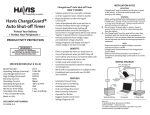
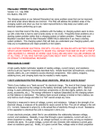
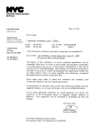
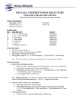
Owner’s Manual
Havis Universal Laptop Mount
UT-101
Havis, Inc.
75 Jacksonville Road, PO Box 2099
Warminster, PA 18974
47801 Anchor Court
Plymouth, MI 48170
www.havis.com
1-800-524-9900
www.havis.com
1-800-524-9900
UT-101_OMN 7-12
Before Beginning
(Original Instructions)
Havis is pleased to provide this Owner’s Manual to aid in the proper installation
and use of the UT-101 Universal Laptop Mount.
For questions regarding the set-up of your UT-101 Universal Laptop Mount, please
contact Havis at 1-800-524-9900 or visit www.havis.com for additional
product support and information.
This Owner’s Manual applies to the following Part Numbers:
UT-101
Related Products
Havis offers a wide variety of accessory products specifically
for use with the UT-101 Universal Laptop Mount.
For more information or to order, please visit www.havis.com.
DS-DA-601
Rugged Communication Hub
Rugged USB/Ethernet hub makes adding peripherals
to your mobile workspace easy and safe.
• NEVER STOW OR MOUNT THE UT-101 DIRECTLY IN A VEHICLE
AIRBAG DEPLOYMENT ZONE.
• DO NOT USE COMPUTER WHILE DRIVING.
SS-UT-X
Screen Stiffener
Secure your laptop screen to prevent excess wear and
reduce vibration while in use.
• READ ALL INSTRUCTIONS THOROUGHLY BEFORE BEGINNING INSTALLATION.
DS-DA-102
USB Powered Keyboard Light
Table of Contents
Specifications
2
Parts Included
3
Configuration
4
Installation
9
Reconfiguring
10
Soft red LED light illuminates the laptop keyboard for
night viewing.
CG-X
ChargeGuard® Auto Shut-off Timer
Power management system that prevents dead
batteries and protects mobile electronics from
voltage anomalies.
Specifications
Universal Laptop Mount Dimensions
Overall Dimensions
13.2” ( 33.5 cm) W x 11.2” ( 28.4 cm ) D x 2.2” ( 5.5 cm ) H
Weight
4.2 lbs ( 1.9 kg )
Width
11.472” (29.1 cm) to 14.192” (36.1 cm)
Depth
9.250” (23.5 cm) to 11.000” (27.9 cm)
Height
Short Lugs: 0.665” (1.7 cm) to 1.265” (3.2 cm)
Tall Lugs: 1.265” (3.2 cm) to 1.865” (4.7 cm)
Compatible Computer Dimensions
2
www.havis.com • 1-800-524-9900
11
Reconfiguring Universal Laptop Mount
Parts Included
If at any time you need to reconfigure your Universal Laptop Mount to secure a
different computer, use the following steps.
Universal Laptop Mount
A
A
C
F
1) Remove laptop computer and ensure the Universal Laptop Mount is latched
by pushing in Side Trays until a click is heard.
2) With access to the bottom of Universal Laptop Mount, loosen the two
Rear Tray Adjustment Screws (A) one full turn, and pull tray outward.
Retighten screws by hand.
C
A
Latch Release Handle
B
Front Fences
C
Rear Fences
D
Side Hold-down Lugs
E
Side Trays
F
Rear Tray
D
D
Top Plate
E
E
D
D
A
B
J
G
B
I
I
I
I
J
G
Bottom Plate
3) Loosen the two Side Tray Adjustment Screws (B) one full turn, and pull the
trays outward. Retighten screws by hand.
B
G
Rear Tray Adjustment Screws
H
Side Tray Adjustment Screws
I
Mounting Holes
J
Strain Relief Holes
K
Power Supply Mounting Area
L
Rugged Hub Mounting Area
H
J
L
J
K
J
B
1
Hardware Kit
4) Return to Page 4 of this Owner’s Manual and begin the Configuration
set-up instructions.
10
J
K
H
This Hardware Kit includes:
1. Zip Ties (4)
2. Star Washer (5)
3. 1/4”-20 Screws (5)
4. Hold-down lug Bumpers (4)
5. Tall Hold Down Lugs (4)
6. Hold-down Lug Vinyl Cap (4)
7. L-shaped Wrench (1)
8. Keys (2)
2
6
3
4
7
5
8
www.havis.com • 1-800-524-9900
3
Configuration
Installation
1) Ensure the UT-101 Universal Laptop Mount is unlatched by pulling the
Latch Release Handle away from the unit.
1) Tip the Motion Device up to allow access to the backside of the through-holes.
2) Before configuring your UT-101 to fit your laptop, make sure you turn the
computer’s power off and remove any connected cords or peripherals.
2) Align the four through-holes in the Motion Device with the four 1/4”-20
threaded mounting holes on the bottom of the Universal Laptop Mount.
Star Washers
(Hardware Kit item #2)
3) Place your laptop in the center of the Universal Laptop Mount. Open your
laptop screen and carefully close the Side Trays by pressing them inward.
4) Check to see that the Side Hold-down Lugs fit over the laptop. There should be
a slight gap between the top of the Side Hold-down Lugs and the laptop deck.
1/4”-20 Screws
(Hardware Kit item #3)
3) Secure Universal Laptop Mount to the Motion Device using the appropriate
hardware. Torque screws to 72 in-lbs (0.8 Nm) ± 10%.
NOTE - If it is necessary to use mounting fasteners other than those provided
in the Hardware Kit, make sure that once mounted, the screw selected will
protrude past the mounting surface into the Universal Laptop Mount by a
minimum of 1/4” (minimum amount of thread engagement needed) and a
maximum of 1/2” (maximum length allowed for acceptable clearance to interior
moving components).
4) If it is necessary to strain relieve wires/cables, insert Integrated Zip Tie/
Push Pin (Hardware Kit item #1) into any of the 1/4” holes on the Bottom
of the Universal Laptop Mount. Loop and tighten Zip Tie around wires/cables,
as required.
4
www.havis.com • 1-800-524-9900
9
Configuration (continued)
Configuration (continued)
10) If any of the Side Hold-down Lugs or Front/Rear Fences are covering ports,
loosen the Lug/Fence screw and gently slide the Lug/Fence along its slot
until port is uncovered. Retighten the screws to 22 in-lbs (0.25 Nm) ± 10%.
5) If the Side Hold-down Lugs installed by the factory are too short, please
follow Steps 5a and 5b. Otherwise, proceed to Step 6.
5a) Locate the adjustment screw for each of the four Side Hold-down Lugs.
Remove the Lug by loosening the screw with the provided L-shaped Wrench.
NOTE: It may not be possible to provide access to all ports on laptop. For your safety, it is
important that all Lugs and Fences be rertained for securing the laptop in place.
11) Make sure your laptop is secure on the Universal Laptop Mount prior
to installation in a vehicle.
Final Check List:
Laptop is in contact with the Front Fences
Side Hold-down Lugs are set to proper height and are in contact
with the deck of the laptop
Laptop is in contact with the Rear Fences
No vital ports or switches are covered by the Side Hold-down Lugs
or Front/Rear Fences where possible
8
5b) Take the four Tall Side Hold-down Lugs from the Packaging and install the
Vinyl Caps and Bumbers on each Lug. Re-install the Tall Side Hold-down
Lugs into the slots on the Universal Laptop Mount and tighten the screws.
Make sure the Lugs fit over the side of the laptop before continuing.
www.havis.com • 1-800-524-9900
5
Configuration (continued)
Configuration (continued)
NOTE: Ensure the laptop is placed in the UT-101 Universal Laptop Mount and the Side
Trays are fully closed before proceeding (press Side Trays together until a click is heard).
6) To adjust the Side and Rear Trays, hold your laptop to the surface of the
Universal Laptop Mount and carefully place the unit upside-down on your lap.
8) With the laptop still completely forward and flush with the two Front Fences,
loosen the screws (B) approximately one full turn. (DO NOT REMOVE SCREWS)
Slide the Rear Tray inward until it touches the back of the laptop. Retighten
the screws (B). Torque screws to 22 in-lbs (0.25 Nm) ± 10%.
B
B
Use caution when placing the
laptop upside-down.
Make sure that you do not
damage the laptop screen.
7) With the laptop completely forward and flush with the two Front Fences,
loosen the screws (A) approximately one full turn. (DO NOT REMOVE SCREWS)
With the laptop centered side-to-side in the Universal Laptop Mount, slide
both Side Trays at the same time inward until they touch the sides of the
laptop. Retighten the screws (A). Torque screws to 22 in-lbs (0.25 Nm) ± 10%.
9) To adjust the Side Hold-down Lugs, turn the laptop on its side and loosen the
screws and slide the Lug down so it makes firm contact with the laptop deck
in order to hold the laptop securely in place. Repeat this step for the remaining
three Side Hold-down Lugs. Turn the entire unit right-side-up and test the Side
Hold-down Lugs to ensure that they are making contact with the laptop deck.
A
A
Laptop should be flush
with Front Fences.
6
www.havis.com • 1-800-524-9900
7
Configuration (continued)
Configuration (continued)
10) If any of the Side Hold-down Lugs or Front/Rear Fences are covering ports,
loosen the Lug/Fence screw and gently slide the Lug/Fence along its slot
until port is uncovered. Retighten the screws to 22 in-lbs (0.25 Nm) ± 10%.
5) If the Side Hold-down Lugs installed by the factory are too short, please
follow Steps 5a and 5b. Otherwise, proceed to Step 6.
5a) Locate the adjustment screw for each of the four Side Hold-down Lugs.
Remove the Lug by loosening the screw with the provided L-shaped Wrench.
NOTE: It may not be possible to provide access to all ports on laptop. For your safety, it is
important that all Lugs and Fences be rertained for securing the laptop in place.
11) Make sure your laptop is secure on the Universal Laptop Mount prior
to installation in a vehicle.
Final Check List:
Laptop is in contact with the Front Fences
Side Hold-down Lugs are set to proper height and are in contact
with the deck of the laptop
Laptop is in contact with the Rear Fences
No vital ports or switches are covered by the Side Hold-down Lugs
or Front/Rear Fences where possible
8
5b) Take the four Tall Side Hold-down Lugs from the Packaging and install the
Vinyl Caps and Bumbers on each Lug. Re-install the Tall Side Hold-down
Lugs into the slots on the Universal Laptop Mount and tighten the screws.
Make sure the Lugs fit over the side of the laptop before continuing.
www.havis.com • 1-800-524-9900
5
Configuration
Installation
1) Ensure the UT-101 Universal Laptop Mount is unlatched by pulling the
Latch Release Handle away from the unit.
1) Tip the Motion Device up to allow access to the backside of the through-holes.
2) Before configuring your UT-101 to fit your laptop, make sure you turn the
computer’s power off and remove any connected cords or peripherals.
2) Align the four through-holes in the Motion Device with the four 1/4”-20
threaded mounting holes on the bottom of the Universal Laptop Mount.
Star Washers
(Hardware Kit item #2)
3) Place your laptop in the center of the Universal Laptop Mount. Open your
laptop screen and carefully close the Side Trays by pressing them inward.
4) Check to see that the Side Hold-down Lugs fit over the laptop. There should be
a slight gap between the top of the Side Hold-down Lugs and the laptop deck.
1/4”-20 Screws
(Hardware Kit item #3)
3) Secure Universal Laptop Mount to the Motion Device using the appropriate
hardware. Torque screws to 72 in-lbs (0.8 Nm) ± 10%.
NOTE - If it is necessary to use mounting fasteners other than those provided
in the Hardware Kit, make sure that once mounted, the screw selected will
protrude past the mounting surface into the Universal Laptop Mount by a
minimum of 1/4” (minimum amount of thread engagement needed) and a
maximum of 1/2” (maximum length allowed for acceptable clearance to interior
moving components).
4) If it is necessary to strain relieve wires/cables, insert Integrated Zip Tie/
Push Pin (Hardware Kit item #1) into any of the 1/4” holes on the Bottom
of the Universal Laptop Mount. Loop and tighten Zip Tie around wires/cables,
as required.
4
www.havis.com • 1-800-524-9900
9
Reconfiguring Universal Laptop Mount
Parts Included
If at any time you need to reconfigure your Universal Laptop Mount to secure a
different computer, use the following steps.
Universal Laptop Mount
A
A
C
F
1) Remove laptop computer and ensure the Universal Laptop Mount is latched
by pushing in Side Trays until a click is heard.
2) With access to the bottom of Universal Laptop Mount, loosen the two
Rear Tray Adjustment Screws (A) one full turn, and pull tray outward.
Retighten screws by hand.
C
A
Latch Release Handle
B
Front Fences
C
Rear Fences
D
Side Hold-down Lugs
E
Side Trays
F
Rear Tray
D
D
Top Plate
E
E
D
D
A
B
J
G
B
I
I
I
I
J
G
Bottom Plate
3) Loosen the two Side Tray Adjustment Screws (B) one full turn, and pull the
trays outward. Retighten screws by hand.
B
G
Rear Tray Adjustment Screws
H
Side Tray Adjustment Screws
I
Mounting Holes
J
Strain Relief Holes
K
Power Supply Mounting Area
L
Rugged Hub Mounting Area
H
J
L
J
K
J
B
1
Hardware Kit
4) Return to Page 4 of this Owner’s Manual and begin the Configuration
set-up instructions.
10
J
K
H
This Hardware Kit includes:
1. Zip Ties (4)
2. Star Washer (5)
3. 1/4”-20 Screws (5)
4. Hold-down lug Bumpers (4)
5. Tall Hold Down Lugs (4)
6. Hold-down Lug Vinyl Cap (4)
7. L-shaped Wrench (1)
8. Keys (2)
2
6
3
4
7
5
8
www.havis.com • 1-800-524-9900
3
Before Beginning
(Original Instructions)
Havis is pleased to provide this Owner’s Manual to aid in the proper installation
and use of the UT-101 Universal Laptop Mount.
For questions regarding the set-up of your UT-101 Universal Laptop Mount, please
contact Havis at 1-800-524-9900 or visit www.havis.com for additional
product support and information.
This Owner’s Manual applies to the following Part Numbers:
UT-101
Related Products
Havis offers a wide variety of accessory products specifically
for use with the UT-101 Universal Laptop Mount.
For more information or to order, please visit www.havis.com.
DS-DA-601
Rugged Communication Hub
Rugged USB/Ethernet hub makes adding peripherals
to your mobile workspace easy and safe.
• NEVER STOW OR MOUNT THE UT-101 DIRECTLY IN A VEHICLE
AIRBAG DEPLOYMENT ZONE.
• DO NOT USE COMPUTER WHILE DRIVING.
SS-UT-X
Screen Stiffener
Secure your laptop screen to prevent excess wear and
reduce vibration while in use.
• READ ALL INSTRUCTIONS THOROUGHLY BEFORE BEGINNING INSTALLATION.
DS-DA-102
USB Powered Keyboard Light
Table of Contents
Specifications
2
Parts Included
3
Configuration
4
Installation
9
Reconfiguring
10
Soft red LED light illuminates the laptop keyboard for
night viewing.
CG-X
ChargeGuard® Auto Shut-off Timer
Power management system that prevents dead
batteries and protects mobile electronics from
voltage anomalies.
Specifications
Universal Laptop Mount Dimensions
Overall Dimensions
13.2” ( 33.5 cm) W x 11.2” ( 28.4 cm ) D x 2.2” ( 5.5 cm ) H
Weight
4.2 lbs ( 1.9 kg )
Width
11.472” (29.1 cm) to 14.192” (36.1 cm)
Depth
9.250” (23.5 cm) to 11.000” (27.9 cm)
Height
Short Lugs: 0.665” (1.7 cm) to 1.265” (3.2 cm)
Tall Lugs: 1.265” (3.2 cm) to 1.865” (4.7 cm)
Compatible Computer Dimensions
2
www.havis.com • 1-800-524-9900
11
Owner’s Manual
Havis Universal Laptop Mount
UT-101
Havis, Inc.
75 Jacksonville Road, PO Box 2099
Warminster, PA 18974
47801 Anchor Court
Plymouth, MI 48170
www.havis.com
1-800-524-9900
www.havis.com
1-800-524-9900
UT-101_OMN 7-12