1
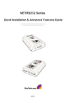
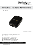
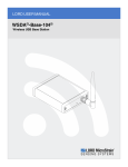
1/2/4/8 Port RS232 Serial over IP
Ethernet Device Server
NETRS232_1
NETRS232_1GB
NETRS232_2
NETRS232_2GB
NETRS232_4
*actual product may vary from photos
DE: Bedienungsanleitung - de.startech.com
FR: Guide de l'utilisateur - fr.startech.com
ES: Guía del usuario - es.startech.com
IT: Guida per l'uso - it.startech.com
NL: Gebruiksaanwijzing - nl.startech.com
PT: Guia do usuário - pt.startech.com
For the most up-to-date information, please visit: www.startech.com
Manual Revision: 05/23/2013
FCC Compliance Statement
This equipment has been tested and found to comply with the limits for a Class B digital
device, pursuant to part 15 of the FCC Rules. These limits are designed to provide reasonable
protection against harmful interference in a residential installation. This equipment generates,
uses and can radiate radio frequency energy and, if not installed and used in accordance with
the instructions, may cause harmful interference to radio communications. However, there
is no guarantee that interference will not occur in a particular installation. If this equipment
does cause harmful interference to radio or television reception, which can be determined by
turning the equipment off and on, the user is encouraged to try to correct the interference by
one or more of the following measures:
• Reorient or relocate the receiving antenna.
• Increase the separation between the equipment and receiver.
• Connect the equipment into an outlet on a circuit different from that to which the receiver
is connected.
• Consult the dealer or an experienced radio/TV technician for help.
Use of Trademarks, Registered Trademarks, and other Protected Names and Symbols
This manual may make reference to trademarks, registered trademarks, and other
protected names and/or symbols of third-party companies not related in any way to
StarTech.com. Where they occur these references are for illustrative purposes only and do not
represent an endorsement of a product or service by StarTech.com, or an endorsement of the
product(s) to which this manual applies by the third-party company in question. Regardless
of any direct acknowledgement elsewhere in the body of this document, StarTech.com hereby
acknowledges that all trademarks, registered trademarks, service marks, and other protected
names and/or symbols contained in this manual and related documents are the property of
their respective holders.
Instruction Manual
Table of Contents
Introduction.............................................................................................1
Packaging Contents.................................................................................................................................. 1
System Requirements............................................................................................................................... 1
Hardware Guide......................................................................................2
Hardware Installation.............................................................................3
Software Installation..............................................................................3
Configuring the Network Settings.......................................................4
Configuring Network Settings Using IP Extender Manager....................................................... 4
Configuring Network Settings Using a Web Browser................................................................... 5
Activating and Deactivating NETRS232 Ports................................................................................. 7
Advanced Settings..................................................................................9
Port Modes................................................................................................................................................... 9
Virtual port (driver) settings................................................................................................................... 10
Virtual port (driver) bindings................................................................................................................. 10
Virtual port COM number assignment............................................................................................... 12
WAN Activation.......................................................................................13
External Configuration............................................................................................................................. 13
Internal Configuration.............................................................................................................................. 13
Specifications...........................................................................................15
Technical Support...................................................................................16
Warranty Information.............................................................................16
Instruction Manual
i
Introduction
Thank you for purchasing a StarTech.com Ethernet Remote Serial interface converter.
With this one, two, or four port converter, your RS-232 serial devices can be placed
anywhere on your Ethernet WAN/LAN and still perform as if they were right beside
you. Even at the longest distances, control of your serial devices will be right at your
fingertips: the remote serial ports appear alongside your local serial ports in your
Windows device manager. This line of interface converters is designed to function
seamlessly with your other serial ports for completely transparent operation. Your
serial equipment – card scanners, access keypads, bar code scanners, and more – will
operate as smoothly as if the serial ports were right inside your computer.
Packaging Contents
• 1 x Ethernet Remote Serial interface adapter
• 1 x power adapter
• 1 x driver disk
• 1 x Instruction Manual
System Requirements
• Microsoft® Windows® 2000/XP/Server 2003/Vista/7 (32-bit) or
Linux® kernel 2.4.x or later
Instruction Manual
1
Hardware Guide
Serial Port
Network LEDs
Instruction Manual
RJ-45 Port
Serial Rx LED
Power LED
2
Serial Tx LED
DC Power Port
Hardware Installation
1. Plug the power adapter into the Power port on the converter and plug the other
end into an available power source. The red Power LED onthe converter should now
be illuminated.
2. Connect the converter to your network by doing one of the following:
•Using a straight-through RJ-45 cable to connect the converter to a hub or switch
•Using a crossover RJ-45 cable to connect the converter to a host PC
Network status is indicated by the two LEDs located on the RJ-45 connector. The left
(yellow) LED indicates network activity. This LED is on by default, and turns off when
network activity occurs at the interface converter. The right (green) LED indicates a
network link. This LED is off by default, and lights up when a network link is established.
NOTE: The interface converter uses a default IP address of 192.168.0.35. If this IP
address is already in use on your network segment, you may first need to connect
the converter to a different network segment or connect it to a PC. To change the IP
address, see “Configuring the Network Settings”.
3. Connect your serial devices to the serial ports on the converter.
Software Installation
To install the required software, you need to run the IP Extender setup software.
• Insert the driver disk into the disk drive and run the setup.exe file.
Follow the onscreen prompts to complete the installation.
The Setup Wizard will finish by opening the IP Extender Manager program. By default, IP
Extender Manager will display any other NETRS232 devices it has detected on your network.
Instruction Manual
3
Configuring the Network Settings
The IP Extender Manager software displays information in a format similar to Windows
Explorer. Any NETRS232 devices on your network are displayed in the “IP Extenders
Near Me” branch of the “My IP Extender Network” tree.
Each NETRS232 device on your network will need a unique IP address. These can be set
up using IP Extender Manager or a Telnet Client.
The factory default settings for the device are:
IP Address: 192.168.0.35
Subnet Mask: 255.255.255.0
Gateway Address: 0.0.0.0
Name: [empty]
Workgroup: [empty]
DHCP Detection: Disabled
Configuring Network Settings Using IP Extender Manager
NOTE: The IP Extender Manager software is the recommended method for changing
all settings.
To change an NETRS232’s network settings using IP Extender Manager, the NETRS232
device must first be unlocked. Right-click on the device and select Unlock. The default
password is “admin”. Then right-click on the device in the IP Extender tree and select
“Properties.” If the device is accessible on the network, a dialog box will appear.
From IP Extender Manager, you can change the Name, IP Address, Subnet Mask, and
Gateway settings for your device. If your network assigns IP addresses through DHCP,
you can also enable the Use DHCP setting.
Note: Changing the network settings of a NETRS232 device may make that device
unavailable to other stations that have activated a connection to that device using
older network settings.
Instruction Manual
4
Configuring Network Settings Using a Web Browser
The NETRS232 converter contains an embedded web server that allows you to
configure your device’s network settings through your web browser. To configure an
NETRS232’s network settings using a web browser, open your web browser and enter
the device’s IP address in the browser’s address bar.
Note: In order to use the embedded web server, you must have assigned your NETRS232
device a specific static IP address, your IP address can not be assigned by your DHCP
server. You also can not change DHCP settings from the embedded web server.
Once on the configuration screen, log into the unit with the default password “admin”.
Choose the setting you wish to change and enter the new network settings. Once the
new values and entered and accepted, the device will reboot in order to implement
the new network settings.
Changes made using the web browser will be updated to the device, but not to the
local PC.
Note: Changing the network settings of an NETRS232 device may make that device
unavailable to other stations that have activated a connection to that device using
older network settings.
Configuring Network Settings Using a Telnet ClientOpen a Telnet session with local
echo on and carriage return/line feed on.
Windows example:
1. Go to Start|Run, type “cmd,” and click on “OK.”
2. A DOS window opens. At the DOS prompt, type “telnet” and press <Enter>.
3. A Telnet console opens. At the Telnet prompt, set local echo on by typing “setlocal_
echo” and pressing <Enter>. Set carriage return and line feed on by typing “crlf” and
pressing <Enter>.
4. Open a Telnet session to the NETRS232 Link. At the Telnet prompt, type “open [IP
address]” and press <Enter>, where [IP address] is the address of the NETRS232 Link
with which you wish to communicate. The NETRS232 Link Telnet screen will open.
5. In the Telnet console, you can configure the NETRS232 Link’s settings, restore the
NETRS232 Link to its factory defaults, or query the NETRS232 Link to display its
current status.
Instruction Manual
5
6. Configure the device. The following network and port settings for the device can be
configured in a Telnet session:
Device settings (for the interface converter device):
• IP address
• Net mask
• Gateway
• NetBios name (Device Name)
• Workgroup
Port settings (for each serial port individually):
• TCP port number
• Port mode (see Advanced Settings on page 8 for a description of the
various port modes)
• Baud rate
• Data bits
• Parity
• Stop bits
• Flow control
After changing settings, the interface converter will be reset.
Instruction Manual
6
Activating and Deactivating NETRS232 Ports
NETRS232 ports that have been detected as existing on the network are not initially
activated for your PC. To access a serial port, you must first activate it. You can activate
a port on one computer, some computers, all computers, or none of the computers on
your network.
To activate a port, open your IP Extender Manager software:
• To activate one port, right-click on the port name (in the right side of the window)
and select “Activate.”
• To activate all ports on a particular device, right-click on the device name (in the left
side of the window) and select “Activate All.”
To deactivate ports, open your IP Extender Manager software:
• To deactivate one port, right-click on the port name (in the right side of the window)
and select “Deactivate.”
• To deactivate all ports on a particular device, right-click on the device name (in the
left side of the window) and select “Deactivate All.”
Activating and deactivating NETRS232 ports on one computer will not affect the
operation of those ports on other systems.
Before activation, the ports will appear under the “My IP Extender Network” branch of
the IP Extender Desktop tree. Once the ports have been activated for a local system,
they will also appear under “My Computer” in the IP Extender Manager. The ports will
also appear in your Windows’ Device Manager under the “Ports (COM & LPT)” branch as
“Virtual Ports.” The ports will be listed with their associated COM numbers.
Instruction Manual
7
There are two icons that depict the state of the NETRS232_x ports and devices:
Icon:
Icon with green square:
Device available on the network.
Under “My Computer,” this icon
means the port is available.
Icon with red X:
Under “My IP Extender
Neighborhood,” this icon means the
port is activated locally.
Device not available on the network.
Icon with red square:
Under “My Computer,” this icon
means the port is not available.
Under “My IP Extender
Neighborhood,” this icon means the
port is not activated locally.
Instruction Manual
8
Advanced Settings
Ports that have been activated on your PC can generally be used without any further
configuration. There are, however, additional configuration options available through
the IP Extender Manager.
Port Modes
The interface converter converts serial port data to and from TCP/IP packets over
Ethernet. Each port exchanges TCP/IP packets on its own unique TCP port (called
the “Local Port” in the Properties dialog box). Each serial port on a device can be
configured independently to perform this conversion in one of four modes. To edit
the port mode settings, open your IP Extender Manager and click on the “Port 1” (or
whichever port you want to edit) tab. Choose from the following:
Windows Mode (Default mode)
This mode causes an NETRS232 serial port to operate as a virtual port on a
Windows 2000/XP PC. In this mode, the port accepts its serial port settings from
the application/operating system that is accessing it. This is the factory default
mode when the device is installed.
Applications: General serial port access from applications running on a PC.
Raw Mode - Server
This mode is used to establish a raw connection to the device. In this mode, the
device accepts those settings specified for the “local port” in the Port Settings
dialog box as its serial port settings. Operating as a server, the device opens the
serial portand buffers serial port data until a client (PC) retrieves it.
Applications: Remote monitoring, security systems.
Raw Mode - Client
This mode is used to establish a raw connection to the device. In this mode,
the device accepts the settings specified for the “local port” in the Port Settings
dialog box as its serial port settings. Operating as a client, the device directs that
port to wait for data from server (PC), then open the serial port and transmit
data. In this mode, the user specifies a target IP address and TCP port for the
device to use.
Applications: Remote control.
RFC2217 Mode
This mode opens an NETRS232 port when a TCP connection is established to
the “local port.” Port settings are embedded in data stream in accordance with
RFC 2217.
Applications: Recommended for use over the Internet.
Instruction Manual
9
Virtual port (driver) settings
The virtual port allows a serial port on an NETRS232 device to be used in same manner
as a local serial port when the port is configured in Windows Mode (described above).
In this state, the driver for the virtual port converts local serial port accesses into TCP/
IP packets to be exchanged with NETRS232 port. Two virtual port settings are provided
to support “difficult” serial devices/applications, generally those with particularly
demanding serial requirements. You can access these settings by right-clicking on
the port name in your Windows’ Device Manager and clicking Properties. From the
Properties tab, click on the Port Settings tab and click on Driver Settings.
Polling Limit
Setting a polling limit for the virtual port driver allows the NETRS232 Link to
support high-speed connections. The serial port is constantly polled for new
data. Polling stops when number of consecutive polls with no new data reaches
the polling limit parameter specified in the dialog box. Since polling introduces
network traffic, this parameter should be set as low as possible without introducing
lag into the connection. To reduce network traffic,reduce the polling limit; to
reduce lag, increase the polling limit. Interactive applications (such as typing)
or applications that exchange bursts of data should use a lower polling limit.
Applications with a constant high data rate should use a higher polling limit.
Compatibility Mode
The virtual port normally operates in high performance mode. Compatibility
mode supports applications that require a more accurate simulation of a local
serial port. Compatibility mode may help when data being sent to the remote
serial port is lost or sent repeatedly.
Virtual port (driver) bindings
In effect, activating an NETRS232 port creates a “virtual” port that is associated with
a particular physical serial port on a particular NETRS232 Link. When a virtual port
is opened, a connection must be established to the appropriate NETRRS232 Link. In
normal operation, that connection is made to the IP address assigned to the NETRS232
Link at the time the activation was created. However, on many Ethernet/IP networks,
the IP address of individual devices may change (for example, when a DHCP server
assigns addresses). This address reassignment will cause virtual ports to fail or make
unintended connections to unintended NETRS232 Links.
Instruction Manual
10
To prevent this difficulty, NETRS232 Links have a “discovery” mode that allows the
correct NETRS232 Link port to be found even when the IP address of the associated
box has changed. To use this discovery mode, a “port binding” must be created for that
virtual port. A port binding is a network identification of the target NETRS232 Link that
must match before a virtual port will initiate a connection. Bindings may be made to
the MAC address, Name, or IP address of the associated device.
You can access these settings by right-clicking on the port name in your Windows’
Device Manager and clicking Properties. From the Properties tab, click on the Bind
Settings tab.
Binding to MAC Address
MAC addresses are unique and permanent identifiers for Ethernet devices, and
are assigned to devices when they are manufactured. Binding to an NETRS232
Link’s MAC address ensures that a virtual port always makes a connection to that
same physical device, even if the device’s IP address or Name have changed.
Binding to MAC address provides security and reliability. Virtual ports will only
connect to that single particular physical device.
Binding to Name
Device Name is a 15-character field assigned by the NETRS232 system
administrator. Binding a virtual port to a device’s Name will ensure that a
connection will be made to an actual port if a device can be found with the name
specified in the ”Bindings” dialog box. This port may be on different physical
device from the one with which the virtual port was initially communicating
(that is, a device with a different MAC address), or it may be a port on the same
physical device but with a changed IP address, or both. Binding to a device’s
Name provides reliability and dynamic connections. Virtual ports will connect
to any device with a name that matches the binding. If a particular device is
replaced with a new one with the same assigned Name, the virtual port will still
make a connection. Also, Names can be reassigned at any time to cause client
PCs to connect to new devices without being recon figured. Binding a virtual
port to a Name allows that virtual port to be identified on the network with a
more representative mnemonic than an IP address or MAC address. For example,
a security system might name its virtual port targets “Camera1,” “Camera2,”
“CardReader6,” and so forth.
Instruction Manual
11
Binding to IP Address
The IP address of a network device is assigned by either the system administrator
or through a DHCP server. Binding a virtual port to an IP address will force that
virtual port to attempt a connection to any device with that particular IP address
only. Binding to an IP address provides dynamic connections. Device IP addresses
can be reassigned at any time to cause client PCs to form new connections
without being reconfigured.
Note: When no bindings have been stipulated, a virtual port is implicitly bound
to an IP address because such an address is required to make a connection.
However, IP Extender Manager will attempt to make intelligent corrections to
unbound virtual ports if it detects any problems. IP bound ports will not be
checked by the IP Extender Manager.
Binding to more than one parameter
Usually, one degree of binding is sufficient for an individual virtual port to
achieve the goals of robust communication and flexibility. It is also possible
to bind a virtual port to more than one parameter. Doing so requires careful
consideration of the implications of maintaining connectivity. If multiple
bindings are selected for one port, all individual binding parameters must
match for a connection to be made. For example, enabling both IP address and
MAC address bindings for a virtual port would cause that virtual port to find a
particular physical device by MAC address, but make a connection only if the
device’s IP address also matched the binding setting.
Virtual port COM number assignment
By default, an NETRS232 Link virtual serial port is assigned to the next available COM
number when it is activated. This COM number assignment can be reassigned to any
unused COM number from 1 to 256. For many applications, an alphanumeric name can
be used instead of a COM number.
Instruction Manual
12
WAN Activation
Activating and accessing the virtual serial port on a NETRS232 device across a WAN can
be done in two different ways, depending on how the NETRS232 device is accessible.
• NETRS232 device is accessible externally – is directly accessible on the Internet.
• NETRS232 device accessible internally – is located behind a gateway or router and is
not directly accessible.
External Configuration
NOTE: All steps assume the Ether-Serial Link has already been configured and is
working on a public IP address.
1. Obtain the IP address of the NETRS232 device
2. Open the embedded web page of the NETRS232 device from your browser by
typing in its IP address in the address bar.
3. Ensure that the port(s) to use WAN activation are configured for “Driver Mode”.
4. Record the TCP port number of the port(s) to be accessed.
5. Open the IP Extender Manager and click on the “WAN Activation” button, located on
the main toolbar. This will open the “WAN Port Settings” window.
6. Enter the IP address of the NETRS232 device and the TCP port number of the first
port you wish to use the WAN activation on, then click OK.
7. This will create a new COM port that you can configure and connect to, as you
would a standard COM port.
8. Repeat for any additional WAN activations you wish to create.
Internal Configuration
NOTE: All steps assume the Ether-Serial Link has already been configured and is
working on a public IP address.
1. Obtain the IP address of the gateway/router that the NETRS232 device is located behind.
2. To configure the NETRS232 device yourself you will need to reconfigure the
gateway/router to allow HTTP port redirection to the NETRS232 device to access the
embedded web page of the NETRS232 device. To do this, please consult either your
system administrator or the technical documentation that accompanied your gateway/
router. If you would rather not turn on HTTP port redirection you can easily have another
user with direct access to the NETRS232 device perform the next three steps.
3. Open the embedded web page of the NETRS232 device from your browser by
typing in its IP address, or the IP address of the gateway/router, in the address bar.
Instruction Manual
13
4. Ensure that the port(s) to use WAN activation on are configured for “Driver Mode”.
5. Record the TCP port number of the port(s) to be accessible.
6. With the IP address and TCP port number(s) of the NETRS232 device in mind,
enable port forwarding on your gateway/router for each port to be made remotely
accessible. This will require you to create a port forwarding association between the
IP address/TCP ports on the NETRS232 device and the TCP ports on the gateway/
router (i.e. A rule specifying that all incoming connections received by the gateway/
router on TCP port x will be forwarded internally to IP address 192.168.0.35 and
x). To do this please consult either your system administrator or the technical
documentation that accompanied your gateway/router.
7. NOTE: Every TCP port that is accessible externally MUST be unique and may not
be shared between multiple internal targets.
8. NOTE: Certain gateways may allow for port redirection (i.e. Any external available
TCP port may be redirected to any IP address and TCP port on the network). If
however your gateway doesn’t support port redirection, then all external TCP port
connections will need to be matched to the exact same internal TCP port number.
As a result, if you wish to make multiple devices accessible over the gateway/router
then you will be
9. required to reconfigure the NETRS232 device to prevent multiple NETRS232
devices from using the same TCP port numbers.
10. Open the IP Extender Manager and click on the “WAN Activation” button, located
on the main toolbar. The “WAN Port Settings” window will open.
Instruction Manual
14
Specifications
Internet Protocols
IP, HTTP, ICMP, TCP, TFTP, and UDP
1 x RJ-45 Ethernet port (female)
1 x DC Power
Connectors
NETRS232_1
1 x DB-9 serial port (male)
NETRS232_2
2 x DB-9 serial ports (male)
NETRS232_4
4 x DB-9 serial ports (male)
1 x Power
LEDs
2 x Ethernet Link/Activity
1 x Serial Tx (per serial port)
1 x Serial Rx (per serial port)
Serial Protocol
RS232
Maximum Data Transfer
Rate
Ethernet: 10Mbps
Power Adapter
12V DC, 200mA, Center-positive
Serial: 115.2Kbps
Operating Temperature
0°C to 70°C (32°F to 158°F)
Storage Temperature
-20°C to 90°C (-4°F to 194°F)
Humidity
0~90% RH
NETRS232_1: 130.0mm x 95.0mm x 44.0mm
Dimensions
NETRS232_2: 130.0mm x 95.0mm x 44.0mm
NETRS232_4: 130.0mm x 95.0mm x 44.0mm
Compatible Operating
Systems
Instruction Manual
Windows 2000/XP/Vista/7 (32-bit), Linux kernel
2.4.x
15
Technical Support
StarTech.com’s lifetime technical support is an integral part of our commitment to
provide industry-leading solutions. If you ever need help with your product, visit
www.startech.com/support and access our comprehensive selection of online tools,
documentation, and downloads.
For the latest drivers/software, please visit www.startech.com/downloads
Warranty Information
This product is backed by a two year warranty.
In addition, StarTech.com warrants its products against defects in materials
and workmanship for the periods noted, following the initial date of purchase.
During this period, the products may be returned for repair, or replacement with
equivalent products at our discretion. The warranty covers parts and labor costs only.
StarTech.com does not warrant its products from defects or damages arising from
misuse, abuse, alteration, or normal wear and tear.
Limitation of Liability
In no event shall the liability of StarTech.com Ltd. and StarTech.com USA LLP (or their
officers, directors, employees or agents) for any damages (whether direct or indirect,
special, punitive, incidental, consequential, or otherwise), loss of profits, loss of business,
or any pecuniary loss, arising out of or related to the use of the product exceed the
actual price paid for the product. Some states do not allow the exclusion or limitation
of incidental or consequential damages. If such laws apply, the limitations or exclusions
contained in this statement may not apply to you.
Instruction Manual
16
Hard-to-find made easy. At StarTech.com, that isn’t a slogan. It’s a promise.
StarTech.com is your one-stop source for every connectivity part you need. From
the latest technology to legacy products — and all the parts that bridge the old and
new — we can help you find the parts that connect your solutions.
We make it easy to locate the parts, and we quickly deliver them wherever they need
to go. Just talk to one of our tech advisors or visit our website. You’ll be connected to
the products you need in no time.
Visit www.startech.com for complete information on all StarTech.com products and
to access exclusive resources and time-saving tools.
StarTech.com is an ISO 9001 Registered manufacturer of connectivity and technology
parts. StarTech.com was founded in 1985 and has operations in the United States,
Canada, the United Kingdom and Taiwan servicing a worldwide market.