1
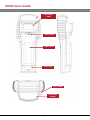
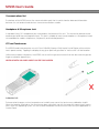
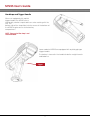
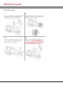
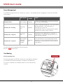
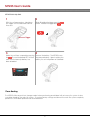
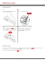
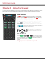
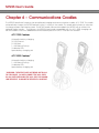
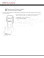
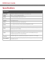
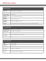
M7225 User’s Guide
Revision History
February 1, 2010 - Initial version
2
M7225 User’s Guide
© 2010 American Microsystems, Ltd.
All rights reserved.
American Microsystems, Ltd. reserves the right to make changes in specifications and other information contained in this document without prior notice, and the reader should in all cases consult American
Microsystems, Ltd. to determine whether any such changes have been made. The information in this publication does not represent a commitment on the part of American Microsystems, Ltd.
American Microsystems, Ltd. shall not be liable for technical or editorial errors or omissions contained herein;
nor for incidental or consequential damages resulting from the furnishing, performance, or use of this material.
This document contains proprietary information which is protected by copyright.
All rights are reserved. No part of this document may be photocopied, reproduced, or translated into another
language without the prior written consent of American Microsystems, Ltd.
FCC Declaration of Conformity
Product Name: Model 7225 Handheld Computer
Model Number: M7225
Radio Frequency Interference Requirements
This equipment complies with Part 15 of the FCC Rules. Operation is subject to the following two conditions: (1)
This equipment may not cause harmful interference, and (2) this equipment must accept any interference
received, including interference that may cause undesired operation.
This equipment has been tested and found to comply with the limits for a Class A digital device, pursuant to
Part 15 of the FCC Rules. These limits are designed to provide reasonable protection against harmful interference when the equipment is operated in a residential environment. This equipment generates uses and can
radiate radio frequency energy, and if not installed and used in accordance with the instructions, may cause
harmful interference to radio communications. However, there is no guarantee that interference will not occur
in a particular installation. If you determine the equipment does cause harmful interference to radio or television reception (this may be determined by monitoring the interference while turning the equipment off and
on), you are encouraged to try to correct the interference by one of the following measures:
·
·
·
·
·
Reorient or relocate the receiving antenna.
Increase the separation between the equipment and receiver.
Connect the equipment into an outlet on a circuit different from that to which the
receiver is connected.
Consult the dealer or an experienced radio or TV technician for help.
Changes or modifications not expressly approved by American Microsystems, Ltd. could void the user's
authority to operate the equipment.
3
M7225 User’s Guide
Normalización y Certificación Electronica (NYCE)
Safety
NOM/NYCE-NOM-019-SCFI-1998
Safety of data processing equipment
American Microsystems, Ltd.
2190 Regal Parkway • Euless, TX 76040
Phone 800.648.4452 • Fax 817.685.6232
www.amltd.com
4
M7225 User’s Guide
Table of Contents
Chapter 1 – Getting Started
Unpacking
7
Installing the Main Battery
M7225 Handheld Units
M7225 Pistol-Grip Units
Charging the M7225
8
8
9
10
Battery Charge Times
System Boot and Startup
Using Windows Embedded CE 6.0
Control Panel
10
11
12
13
Chapter 2 - M7225 Hardware
External Drawings
14
Communications Port
Headphone & Microphone Jack
LCD and Touchscreen
Calibration Drift
16
16
16
16
Handstrap and Trigger Handle
Installing a MicroSD Card
M7225 Handheld Units
M7225 Pistol-Grip Units
17
18
18
19
Power Management
Cold Booting
M7225 Handheld Units
M7225 Pistol-Grip Units
20
20
20
21
Clean Booting
M7225 Handheld Units
M7225 Pistol-Grip Units
21
22
22
Chapter 3 - Using the Keypad
System Control Keys
23
Func, Shift, Alt, & Ctrl
Menu
General Keys
23
24
24
5
M7225 User’s Guide
Chapter 4 - Barcode Scanning
Available Scanner Types
Supported Symbologies
Scanner Reading Distances
25
25
26
Standard Range Laser
Long Range Laser
Two-Dimensional Imager
SCAN Button and Trigger
26
27
27
28
Scanning Barcodes
Configuring the Barcode Scanner
Barcode Scanner Modes
User Feedback
28
29
29
29
Good Read / Bad Read Feedback
Data Editing
Advanced Scanner Configuration
30
31
31
Chapter 5 - Wireless Networking
General Overview
32
802.11 Fallback
Interference and Coexistence
Encryption and Authorization
Configuration with ZeroConfig
32
32
33
34
Configuration with Summit Client Utility
35
Chapter 6 - Communications Cradle
ACC-7225 Communications Cradle
ACC-5925 Charging Cradle
Indicator Lights
ACC-7225 Communication Ports
36
36
37
37
Specifications
General Specifications
Performance Specifications
Environmental Specifications
Wireless Radio Specifications
38
39
39
39
High-Power Summit® Radio Specifications
Bluetooth® Radio Specifications
Regulatory Specifications
ACC-7225 Communications Cradle Specifications
40
40
40
40
6
M7225 User’s Guide
Chapter 1 - Getting Started
Unpacking
Verify that all of the following items are included with the terminal:
• M7225 Hand-held Computer
• Main Battery (14.4Wh)
• Plastic Stylus
• Quick Start Guide
7
M7225 User’s Guide
Installing the Main Battery
M7225 Handheld Units
1
2
Unlock the battery compartment
by turning the access latch
counter-clockwise.
Remove the battery door by hinging it
upward.
3
4
Insert the main battery near the rear of
the compartment and slide towards
the front to engage.
Replace the battery door and lock the
access latch.
2
1
8
M7225 User’s Guide
M7225 Pistol-Grip Units
1
2
Unlock the battery compartment
by turning the access latch
counter-clockwise.
Remove the battery door by hinging it
upward.
3
4
Insert the main battery near the rear of
the compartment and slide towards
the front to engage.
Replace the battery door and lock the
access latch.
9
M7225 User’s Guide
Charging the M7225
The M7225 uses two batteries to supply power to the system. During
normal operation, the unit is powered from the main battery pack
installed in the rear battery compartment. During battery changes,
the system’s memory is retained by an internal backup battery.
The main battery is charged through the port located on the bottom
of the M7225 unit. To charge the main battery, insert the M7225 into
a charging cradle or a communications cradle.
The internal backup battery will be charged from the main battery
only when the main battery contains at least a 60% charge. This limits
the power being drawn from the main battery and conserves main
battery life. The backup battery will also charge when the M7225 is
seated properly in a charging cradle without regard to the main battery charge state.
IMPORTANT: Only use AML batteries and chargers. Use of any nonAML branded batteries or chargers may cause damage not covered
under warranty.
Battery Charge Times
Before Initial Use
Full Charge Time
Main Battery
4 hours
5 hours
Backup Battery
1 hour
2 hours
10
M7225 User’s Guide
System Boot and Startup
When a charged main battery is inserted into the M7225 for the first time, the unit will
automatically power on and start the Initial Program Load (IPL) or “Cold Boot”. This
process will take about 4 minutes to complete. Do not press any keys on the keyboard or remove the main battery during the cold boot process.
During cold boot, the Windows Embedded CE 6.0 operating system is copied out of
the internal flash memory into the unit’s RAM. Once copied, Windows CE will run fully
out of the much faster RAM memory. Running the operating system from RAM rather
than directly from the Flash memory allows applications to run more quickly and
smoothly in the operating system.
After the boot process completes, the M7225 will let the user calibrate the touch
screen and set the system’s real-time clock.
The Welcome
screen will
appear after
the system has
fully booted.
Calibrate the
touch screen
by pressing
down on the
screen with a
stylus where
indicated.
Set the realtime clock to
the current
time and date.
11
M7225 User’s Guide
Using Windows Embedded CE 6.0
After completing the touchscreen calibration and time setup, the M7225 desktop will appear. Users that are
familiar with Microsoft Windows desktop PCs will find the functionality of Windows Embedded CE 6.0 familiar.
7
8
6
2
1
4
5
3
1
Start Button – Used to access system functions and applications
2
Current Windows List – Used to view all open windows
3
SIP Icon – Used to enabled/disable the software keyboard
4
Wireless Network Status – Shows the current status of the wireless network
and used to access wireless security settings
5
USB ActiveSync Status – Shows current status of the ActiveSync connection
6
Program Icons – Used for quick access to user programs
7
My Device Icon – Gives access to system files and Control Panel
8
Recycle Bin – Used to store files that are to be deleted
12
M7225 User’s Guide
Control Panel
The Control Panel houses all system configuration and settings applications.
Barcode
Config
Configure the integrated
barcode scanner options
Bluetooth
Search for and pair with
other Bluetooth devices
Network &
Dial-up
Owner
Certificates
Manage security certificates
for wireless security and
internet encryption
Date/Time
Adjust the system’s date
and time settings
PC
Connection
Dialing
Configure remote dialing
Power
Display
Setup and configure the
display and backlight
Radio Power
Password
Modify general networking
settings
Configure information
about the owner of the
device
Enable password protection
Adjust how the unit
connects to a PC via
ActiveSync
View battery status and
configure power
management options
Enable and disable
different wireless radios to
save power
Input Panel
Modify how the on-screen
keyboard functions
Remove
Programs
Remove previously
installed programs
Internet
Options
Configure internet settings
like Proxy servers and web
browser home page
Storage
Manager
View information about
storage cards and user
flash storage
Keyboard
Configure how the general
keyboard system works
Stylus
M7225 Info
View information about
the M7225 such as
Firmware Version
Mouse
Configure how the mouse
works
13
Calibrate the touchscreen
System
View information about
the Windows Embedded
CE OS
Volume &
Sounds
Adjust the system volume
and audio events
M7225 User’s Guide
Chapter 2 – M7225 Hardware
External Drawings
Speaker
Beeper
Stylus
LCD &
Touchscreen
Scan Key
Power Key
Backlight Key
Audio Jack
Cradle Port
14
M7225 User’s Guide
Laser Safety
Label
Battery Latch
Battery Door
Serial Label
Stylus Holder
Scan Engine
Window
15
M7225 User’s Guide
Communications Port
The bottom of the M7225 houses the communications port that is used to transfer data and information
between the unit and external devices via a communications cradle.
Headphone & Microphone Jack
A standard 3-ring 1/8” headphone jack is located on the bottom of the unit. This connector provides mono
audio output and mono microphone input. This jack is suitable for most mono-earphone + microphone headsets available for cordless telephones, cell phones, and industrial products.
LCD and Touchscreen
The M7225 hand-held computer uses a 3.5 inch 240x320 (Quarter-VGA) Liquid Crystal Display with a resistive
touch panel overlay. Tapping the display at any given point will generate a “mouse click” at that location.
Unlike many modern cell-phones, the M7225 uses a resistive-type touchscreen that can be used with gloved
fingers or a plastic tipped stylus.
NEVER USE METAL OR SHARP OBJECTS ON THE TOUCHSCREEN.
Calibration Drift
Environmental changes such as temperature or humidity may cause the touchscreen calibration to drift.
When the location touched on the touchscreen does not match up with the area of the perceived “mouse
click” within the operating system, the user should recalibrate the touchscreen from the Stylus application in
Control Panel.
16
M7225 User’s Guide
Handstrap and Trigger Handle
When not equipped with a pistol
trigger handle, the M7225 uses a
high-quality comfort strap to aid users when working with the
unit. The
bottom clip of the strap slides into the recess at the bottom of
the M7225 to give access to the battery
compartment.
NOTE: Removal of the strap is not
recommended.
Some models of M7225 are equipped with a pistol-grip-type
trigger handle.
The battery is housed in the handle for better weight transfer
and balance.
Trigger
17
M7225 User’s Guide
Installing a MicroSD Card
The M7225 has a user accessible microSD card slot in the main battery compartment. This slot can accomidate up to a 4GB microSD card for use additional memory expansion. The SD card will be mounted as
“Storage Card” in the operating system.
M7225 Handheld Units
1
2
Remove the battery compartment
cover and main battery.
Locate the microSD card slot. To open
the socket, slide the metal tab to the
right and hinge upward.
3
4
Insert the microSD card fully into the
slot. Hinge the tab downward and
slide into the locked position.
Replace the battery door and lock the
access latch. THE UNIT MUST BE COLD
BOOTED AFTER INSERTING A SD CARD!
18
M7225 User’s Guide
M7225 Pistol-Grip Units
1
2
Remove the battery and loosen the four
pistol grip screws with a Phillips style
screwdriver.ch counter-clockwise.
Locate the microSD card slot. To open
the socket, slide the metal tab to the
right and hinge upward.
3
4
Insert the microSD card fully into the
slot. Hinge the tab downward and
slide into the locked position.
Replace the pistol-grip and tighten the
four screws. Do not over-tighten the
screws! THE UNIT MUST BE COLD BOOTED AFTER INSERTING A SD CARD!
19
M7225 User’s Guide
Power Management
The M7225 is designed to be an “always-on” device. The possible power management states of the M7225
are as follows:
Backup
Battery
Main Battery
Powered Down
Not Installed
System
Disabled
System is in a dead state. Inserting a main battery will cause a cold boot.
Powered On - Running
Powering
Unit
Disabled
System is up and running fully. This is the normal
operating mode. If the main battery is
removed, the system will
automatically switch to suspend and the backup battery will retain system memory.
Powered On - Suspend
Powering
Unit
Disabled
Main battery will supply power if installed. If
main battery is removed, backup battery will
keep memory retained.
Powered On - Suspend
Not Installed
or below
minimum
charge
Powering
Unit
If the main battery is removed during normal
operation, the unit will be forced into suspend
mode and the backup battery will proved necessary power.
To switch between Suspend and Running states,
press the
button once.
Cold Booting
Reset Button
M7225 Handheld Units
To fully power down the M7225, remove the main battery and press
the internal RESET button located in the battery compartment.
The system will perform a cold boot upon the next main battery
insertion.
20
M7225 User’s Guide
M7225 Pistol-Grip Units
1
2
With the unit powered on, hold down
the trigger until the barcode scanner
times out.
While still holding the trigger, press the
button. Release the trigger and
.
Trigger
3
4
Wake the unit from suspend by pressing Remove the battery. The M7225 is now
the
The red keyboard LED will indi- fully powered down. Upon insertion of a
cate that the backup battery has
battery, the unit will perform a Cold Boot.
been disabled.
Clean Booting
The M7225 utilizes a persistent storage model where performing a cold boot will not cause the system to lose
user data stored on the main file system. To restore factory settings and format the main file system complete,
perform a CLEAN boot procedure as outlined below.
21
M7225 User’s Guide
M7225 Handheld Units
1
2
Remove the battery compartment
cover and main battery.
Press the internal RESET button.
3
4
While holding down the
button
on the keypad, re-insert the main battery and replace the battery cover.
The unit will display CLEAN BOOTING on
the LCD to confirm the procedure.
Once the message is visible, release
the power button.
Reset
Button
M7225 Pistol-Grip Units
Power down the M7225 as described in the Cold Booting section. Hold down the
button when re-inserting
the main battery. The unit will display CLEAN BOOTING on the LCD to confirm the procedure.
Once the message is visible, release the
button.
22
M7225 User’s Guide
Chapter 3 – Using the Keypad
The M7225 Terminal is equipped with fifty-five keys that are divided into grey, black, blue, and green keys. When
pressed, each key emits an audible beep to indicate that the M7225 terminal has detected the key press.
System Control Keys
The
key suspends and resumes the M7225 unit. During normal
operation, when the
key is pressed once, the system will switch
to the low power suspend or “sleep” mode. Pressing
again will
return the unit to the fully operational mode.
During normal operation, if the unit is idle for more than 30 seconds,
the LCD backlight will automatically dim to save battery power.
Pressing
the key will restore the backlight to the user definable
setting.
The
button activates the M7225 scan engine. The button is
conveniently located for right or left hand use.
The top portion of the keypad consists
of four arrow keys and two Enter keys.
Func, Shift, Alt, & Ctrl
Pressing
,
,
the current application. Pressing
selects the F-key of the same
number.
, or
selects special functions of
each key as determined by
followed by a number key
To toggle Caps Lock on or off, hold Func and press Shift.
23
M7225 User’s Guide
Menu
Pressing the
key will bring up the standard Windows Embedded CE 6.0 Start Menu.
General Keys
The keypad is designed to function like a standard PC keyboard. To all applications running on the Windows
Embedded CE operating system, the keyboard will function like any other keyboard input.
24
M7225 User’s Guide
Chapter 4 – Barcode Scanning
The M7225 handheld terminal normally comes equipped with a barcode scan engine that is capable of scanning single dimensional and, optionally, two-dimensional barcodes.
Available Scanner Types
Types
1D
Stacked
2D
Scanning Method
Standard Laser
Uses a moving laser light & a standard laser detector.
Long Range Laser
Uses a moving laser light with a highly
sensitive laser detector.
2-Dimensional Imager
Uses LED light & a CCD detector to
“image” the
bar code.
Supported Symbologies
Symbologies
Standard Laser
Long Range Laser
UPC/EAN
Code 128
Code 39
Code 93
Code 11
Interleaved 2 of 5
Discrete 2 of 5
Chinese 2 of 5
Codabar
25
2-Dimensional Imager
M7225 User’s Guide
Symbologies
Standard Laser
Long Range Laser
MSI
RSS/GS1
Postal Codes
Aztec
Code 16K
Code 49
DataMatrix
MaxiCode
MicroPDF
PDF417
QR Code
Codablock
Scanner Reading Distances
Standard Range Laser
26
2-Dimensional Imager
M7225 User’s Guide
Long Range Laser
2D Imager
27
M7225 User’s Guide
SCAN Button and Trigger
The M7225’s internal barcode scanners are designed to be manually triggered by the operator by either pressing the keypad’s
button or by pulling the trigger if the unit is equipped with a pistol-grip-type handle.
Scan Engine
Window
Trigger
Scanning Barcodes
M7225 units equipped with the laser scan engines require proper alignment of the bar code under the scanner
window.
The 2D, omni-directional imager is capable of scanning bar codes at any orientation as long as the entire symbol is visible to the scanner and illuminated.
28
M7225 User’s Guide
Configuring the Barcode Scanner
The barcode scanner can be configured by selecting the Barcode Setup icon in Control Panel.
Barcode Scanner Modes
The internal barcode scanner can be used in two different data modes:
keyboard wedge and serial. When used in keyboard wedge mode,
scanned barcode data will be seen as if the user had typed the data on
the keypad. This allows easy integration into applications that do not
explicitly support barcode scanners.
When keyboard wedge mode is disabled, the barcode data is not routed
through the keyboard buffer. In this mode, the barcode data can be
read by applications from the special “BCD1:” device.
User Feedback
To configure the user feedback settings for barcode scanning, select the
User Feedback button.
Good Read Group
The checkboxes in the Good Read group enable and disable the different feedback options when a barcode is successfully scanned.
Failed Read Group
The checkboxes in the Failed Read group enable and disable the different feedback options to be utilized when the trigger or SCAN button is
pressed, but no barcode is read.
29
M7225 User’s Guide
Feedback
Good Read Group
Failed Read Group
OnScreen
Verification
When enabled, the
entire LCD screen
will flash green
after a good barcode scan.
When enabled, the
entire LCD screen
will flash red after a
failed barcode
scan.
LED Flash
When enabled, the
keyboard LED will
blink green after a
successful barcode
scan.
When enabled, the
keyboard LED will
blink red after a
failed barcode
scan.
Vibrate
When enabled, the
unit will slightly vibrate
to indicate a good
barcode scan.
When enabled, the
unit will slightly vibrate
to indicate a failed
barcode scan.
Audio Sound
When enabled, the
unit will play a good
read sound through
the audio speaker.
The volume of this
sound can be adjusted by changing the
system volume in
Control Panel.
When enabled, the
unit will play an alert
sound through the
audio speaker. The
volume of this sound
can be adjusted by
changing the system volume in
Control Panel.
30
M7225 User’s Guide
Data Editing
The Data Editing dialog allows the user to configure the basic data input stream of the barcode data.
Termination Character – adds a character to the end of all barcode
scans
Prefix – Prepends the barcode data with the given string
Suffix – Appends the barcode data with the given string
Strip Spaces – Delete all space characters from the barcode data before
processing
Prefix/Suffix Special Characters
\\
Literal backslash
\t
Tab character
\e
Escape character
\f
Form Feed character
\r
Enter Keypress
\n
Carriage Return
\l
Line Feed
Advanced Scanner Configuration
Further configuration of the barcode scanner properties is possible through configuration barcodes. For more
information on how to obtain barcode scanner configuration manuals, contact AML.
31
M7225 User’s Guide
Chapter 5 – Wireless Networking
General Overview
The M7225 can contain an optional 802.11b/g radio and internal antenna. This radio is specifically designed to
communicate with any 802.11b/g Access Point.
The range of the radio depends greatly on the
quality of the Access Point and the RF communications characteristic of the environment
where the device is used. The typical range for
an 802.11 radio is 300 feet through free air.
Additional Access Points must be added to
improve coverage in a larger area, or in electrically noisy RF environments.
802.11 Fallback
Wireless LAN technology is designed to make maintaining a connection between two devices as reliable and
consistent as possible. Since the speed of the connection between wireless devices will vary as range and signal quality varies, the wireless devices will intentionally sacrifice throughput (data rate or connection speed as
measured in bits per second) in exchange for maintaining a reliable connection. In other words, a reliable
connection at a lower speed is preferred over an unreliable connection at a higher speed (i.e., it is easier to
maintain the connection if data rate is deliberately reduced, or put another way, lower data rates will tolerate
a higher range and/or worse signal quality). This characteristic is known as fallback. As example, an 802.11b
system will fallback from 11 Mbps to 5.5 Mbps as range increases or signal quality decreases. Subsequent fallbacks from 5.5 Mbps to 2 Mbps and 1 Mbps are also supported.
Interference and Coexistence
802.11 operates in a range of radio frequencies known as an "unlicensed" band (i.e. the FCC does NOT require
the use of a license in order to operate a radio transmitter in this range). This means that commercially available radio devices other than wireless LAN devices are permitted to use the same frequency band as 802.11.
Consequently, these co-existing radio devices can interfere or "jam" the wireless LAN (and vice versa). The
most troublesome devices are cordless telephones and microwave ovens.
Fortunately, higher quality cordless phones tend to "listen" for a clear channel before becoming active and will
thus avoid interfering with a wireless LAN (i.e., the cordless phone seeks a clear channel for itself so naturally
avoids being interfered with or being a source of interference). Jamming from microwave ovens is more
severe but is usually restricted to the upper frequency range for 802.11 (it should be noted that 802.11b/g
divides the available frequency band into 11 channels [US]. The higher numbered channels are most susceptible to microwave oven interference).
In each instance, jamming occurs only when the cordless telephone or microwave oven is active.
32
M7225 User’s Guide
Encryption and Authorization
Much has been publicized in the mass media recently about security problems with wireless LANs. Although it
cannot be denied that some encryption algorithms currently used in 802.11 are flawed, the fact is that security
breaches of a wireless LAN require a deliberate attempt to access the network by an intruder.
The primary issue is that many current users of wireless LAN have opted NOT to turn on security features. If users
were to enable the security features currently available (including only allowing known systems access to the
network and enabling WEP [Wired Equivalent Privacy] or WPA [Wifi Protected Access]) on even the most basic
access points, the intruder's work is much harder. Much as a burglar will stray away from a house whose doors
and windows are securely locked, so too will an attacker tend to move past a wireless network when even the
simplest security measures are enables.
33
M7225 User’s Guide
Configuration with ZeroConfig
To configure the M7225’s wireless radio, enter the Windows Embedded CE 6.0 Wireless ZeroConfig utility by
selecting the Network Status Icon on the desktop and scrolling over to the Wireless tab.
To configure the M7225’s wireless radio, enter the Windows Embedded CE 6.0 Wireless ZeroConfig utility by
selecting the Network Status Icon on the desktop and scrolling over to the Wireless tab.
1
Select the wireless network you
wish to connect to and select
“Connect”.
2 Select the proper Encryption
and authentication types for your
network. Note that not all encryptions are usable with all authentication types.
Network Status
Icon
3
Once all values are
configured for your network, select “OK”.
34
M7225 User’s Guide
Configuration with Summit Client Utility
When equipped with the optional Summit 802.11 radio, the Summit Client Utility (SCU) is used to configure the
wireless network settings on the device.
Visit Summit Data Communications website at
www.summitdatacom.com for more information.
35
M7225 User’s Guide
Chapter 6 – Communications Cradles
The M7225 Hand-held Computer has an optional charging and communications cradle, ACC-7225. The cradle
automatically charges the M7225 batteries while it is resting in the cradle. The cradle also includes an extra slot
to charge a spare main battery pack. The M7225 cradle can accommodate the M7225 with or without the
optional trigger handle. Furthermore, the M7225 is backwards compatible with the ACC-5925 charging cradle for situations where the additional communication ports of the ACC-7225 are not needed.
ACC-7225 Features
Automatic battery charging
10/100 Ethernet
2 x USB Host
1 x USB Slave (Device)
3 Indicator LEDs
Spare battery charging slot
ACC-5925 Features*
Automatic battery charging
1 x USB Slave (Device)
3 Indicator LEDs
Spare battery charging slot
*WARNING: THE M7225 DOES NOT BRING OUT RS-232
TO THE CRADLE. DO NOT CONNECT THE ACC-5925’S
RS-232 PORT WHEN USING THE ACC-5925 FOR CHARGING THE M7225. DAMAGE TO THE M7225 CAN RESULT.
36
M7225 User’s Guide
All compatible cradles have three indicator lights:
POWER - Indicates that the M7225 Cradle is plugged in.
MAIN - Indicates the M7225 main battery is charging.
SPARE - Indicates the spare battery is charging.
When the battery charging LED is red, the battery is charging. When the battery charge LED is green the battery is fully charged.
The ACC-7225 has four communication ports and one power jack located on the rear of the cradle. From left to right, these ports are:
2 x Stacked USB 1.1 Host - Full-size Type A
1 x 10/100 Ethernet Networking
1 x 2.1mm 5V DC Center Positive Power Jack
1 x USB 1.1 Slave – Full-size Type B
All configuration of the ports and setup of external devices connected to
the ACC-7225 is done through the M7225 unit. The ACC-7225 has no
internal or external settings that can be changed.
37
M7225 User’s Guide
Specifications
General Specs
Dimensions
225 mm L x 89 mm W x 57 mm D (8.9” L x 3.5” W x 2.3” D)
Weight
500g / 17.6 oz (w/o optional handle)
Display
3.5” QVGA (320x240), 16-bit Color TFT LCD
Touchscreen
Integrated Resistive Touch Panel
Keypad
55-key alphanumeric
Power
7.4V, 2200mAh Lithium-ion; 15.84 watt-hours
Internal Backup
Battery
3.7V, 160mAh Lithium-ion; retains memory during battery swaps
I/O Ports
USB Host/Slave - expands through communication cradle
WLAN
Standard Internal 802.11b/g radio with integrated Bluetooth; Optional high-power
(63mW) Summit 802.11a/b/g
WPAN
Bluetooth Class 2 on-chip with standard radio
Audio
Hi-Fi Digital Audio codec with up to 48MHz sample rate; Integrated Speaker and
Amplifier; Internal headphone/microphone driver with standard 3.5mm jack;
Integrated high-power scan engine beeper
Bar Code
Scanning
Standard Range Laser; Optional Long Range Laser; Optional 2D Omni-Imager
User Feedback
OnScreen Scan Verification; Beeper/Speaker; Internal programmable vibration motor;
Good/Bad read LED
38
M7225 User’s Guide
Performance Specs
Processor
Samsung® S3C2440 @ 400 MHz
Architecture
32-bit RISC ARM9 with AMBA (Advanced Microcontroller Bus Architecture)
Memory (RAM)
128 MB RAM
Memory (Flash
storage)
128 MB Integrated Flash ROM
Memory
Expansion
microSD Card Socket
Operating
System
Windows® Embedded CE 6.0 R2
Software
Internet Explorer®; Remote Desktop; VT100/220, TN3270, TN5250 Emulation
Environmental Specs
Operating Temp
-20° to 50° C / -4° to 122° F
Storage Temp
-30° to 60° C / -30° to 140° F
Humidity
0% to 90% RH, non-condensing
Electrostatic
Discharge
15kVDC through air; 8kVDC contact
Sealing
IP54; NEMA 12
Wireless Radio Specs
Radio
IEEE 802.11b/g
Frequency
2.4 GHz Range
Output Power
15 dBm (30 mW)
Receive
Sensitivity
-90 dBm @ 1 Mbps, 8% PER
Security
None; 64/128 Bit WEP; WPA/WPA2 Personal (PSK); WPA/WPA2 Enterprise (EAP);
802.1X Authentication Supplicants
39
M7225 User’s Guide
High-power Summit® Radio Specs
Radio
IEEE 802.11a/b/g
Frequency
2.4 GHz Range
Output Power
18 dBm (63 mW)
Receive
Sensitivity
-96 dBm @ 1 Mbps
Security
None; 64/128 Bit WEP; WPA/WPA2 Personal (PSK); WPA/WPA2 Enterprise (EAP);
802.1X Authentication Supplicants; Cisco Compatible Extensions (Version 4)
Bluetooth® Radio Specs
Radio
IEEE 802.15 (On-chip with standard wireless radio)
Frequency
2.4 GHz Range
Output Power
4 dBm (Class 2)
Receive
Sensitivity
-84 dBm @ 1 Mbps, 0.1% BER
Regulatory Specs
Certifications
FCC, CE
Environmental
RoHS, Pb-Free
ACC-7225 Communications Cradle
USB Port
Expansion
1 x USB Slave; 2 x USB Host
Networking
Expansion
10/100 Ethernet LAN
Battery
Charging
1 x Spare Battery; 1 x M7225 unit
40
M7225 User’s Guide
AML
2190 Regal Parkway
Euless, TX 76040
Toll-Free: 800-648-4452
Local: 817-571-9015
Fax: 817-571-6176
Website: www.amltd.com
Hours of Operation: (M-F) 8:00 am - 5:00 pm CST
Sales & Customer Service
Toll-Free: 800-648-4452
Fax: 817-685-6232
Email: [email protected]
Technical Support
Phone: 877-842-3990
Fax: 817-685-6232
Email: [email protected]
41