1
KDT750 User’s Guide
Revision History
November 11, 2008 – Initial version
November 25, 2008 – Merge Integration Guide and User's Manual
December 1, 2008 – Minor punctuation fixes and additions, better unit introduction, add
wireless network diagram, remove MT7570 reference in Appendix B
April 9, 2009 – Updated to include KDT750 Setup Utility. Remove references to manual settings file editing. Add information on updated boot procedure and User Applications.
PRE-1
KDT750 User’s Guide
© 2009 American Microsystems, Ltd.
All rights reserved.
American Microsystems, Ltd. reserves the right to make changes in specifications and other
information contained in this document without prior notice, and the reader should in all
cases consult American Microsystems, Ltd. to determine whether any such changes have
been made. The information in this publication does not represent a commitment on the
part of American Microsystems, Ltd.
American Microsystems, Ltd. shall not be liable for technical or editorial errors or omissions
contained herein; nor for incidental or consequential damages resulting from the furnishing,
performance or use of this material.
This document contains proprietary information which is protected by copyright.
All rights are reserved. No part of this document may be photocopied, reproduced or translated into another language without the prior written consent of American Microsystems,
Ltd.
American Microsystems, Ltd.
2190 Regal Parkway • Euless, TX 76040
Phone 800.648.4452 • Fax 817.685.6232
www.amltd.com
PRE-2
KDT750 User’s Guide
Table of Contents
About This Document
Introduction
What to Expect
Chapter Descriptions
Related Documents
Chapter 1 – Introduction
Introducing the KDT750
Part Numbers and Model Information
Warranty Information
Agency Compliance
Chapter 2 – Getting Started
KDT750 Startup Sequence
Entering System Setup
Navigating Setup
Changing the User Boot Application
Chapter 3 – Terminal Overview
Outer Case Description
Rear Panel Description
Opening the KDT750 Outer Case
Internal Connections
Internal Connector Pinouts
External Connections
Wiring Installation
Power Requirements and Battery Information
Main Power Switch and Power-On Reset
Secure Digital (SD) Card
Chapter 4 – Communications and Input
Network Communications
Serial Communications
USB Communications
Digital I/O
Weigand Interface
Software Keyboard Wedge
Pushbutton Input
PRE-3
KDT750 User’s Guide
Chapter 5 – Wireless Networking
Overview
802.11 Fallback
Interference and Coexistence
Encryption and Authorization
Wireless Configuration
Wireless Network Parameters
Example Configurations
Chapter 6 – Integrated Bar Code Scanner
Overview
Determining Scanner Type
Linear CCD Aiming System and Decode Zones
2D Omni Scanner Aiming System and Decode Zones
Triggering the Scanner
Scanning Bar Codes
Supported Bar Code Symbologies
Obtaining and Using Scan Engine Setup Bar Codes
Chapter 7 – Installed Software
PCDemo
KDT750 Demo
Bar Code Data Viewer
Links2 Web Browser
On-Screen Keyboard
VT100.220 Terminal Emulator
Chapter 8 – Mechanical Integration and Mounting
Rear Panel Mount Points
Flush Wall Mounting
Angled Wall Mounting
Column/Post Mounting
RAM Mounts
Appendix A – Technical Specifications
Appendix B – Wireless Reference Table
PRE-4
KDT750 User’s Guide
About this Document
Introduction
This document describes the integration and general use of the AML KDT750 price verification
terminal.
This document is provided as PRELIMINARY ONLY and is not intended as a complete product
reference. AML reserves the right to make changes to this document and to any hardware,
software or product it describes.
What to Expect
This user's guide provides an overall physical description, built-in hardware functions, technical specifications and performance capabilities of the KDT750 terminal. In addition you will
learn how to:
·
·
·
·
·
Open the tamper resistant case
Connect communication cables
Cold boot and warm reset the KDT750
Navigate the KDT750 software
Mount the unit using optional accessories
Chapter Descriptions
Chapter 1 – gives a brief overview of the KDT750, its product warranty and agency compliance
Chapter 2 – gives a quick start introduction to the KDT750 unit
Chapter 3 – describes the KDT750 terminal hardware and details internal and external
cable connections
Chapter 4 – describes the communication and user input capabilities of the KDT750
Chapter 5 – describes the use and configuration of the optional 802.11 wireless LAN radio
Chapter 6 – describes the use of the optional internal bar code scanner
Chapter 7 – describes the KDT750's preinstalled software suite
Chapter 8 – describes methods to mount the KDT750 unit in a variety of environments
1
KDT750 User’s Guide
Related Documents
KDT750 – APL: AML Price Lookup Protocol, Revision 20081106BMC
2
KDT750 User’s Guide
Introduction
This chapter gives a brief overview
of the KDT750, it’s product warranty
and agency compliance.
1-1
KDT750 User’s Guide
Introducing the KDT750
The KDT750 is an industrially rated, kiosk-style data terminal designed for use in retail price
checking, retail data collection, real-time work-in-process, industrial data collection, consumer lookup and time and attendance.
The terminal is designed around a 5.6” Full VGA, high-color LCD with integrated touchscreen that provides an unsurpassed viewing experience. The ultra-bright LED backlight
allows for viewing images and text on the screen in even the brightest of environments.
The KDT750 is designed to be connected to multiple external and internal data sources
including bar code scanners, magnetic stripe readers, keyboards, proximity card readers
and other modern information collection devices. Its primary wide area communication is
through an integrated Power-over-Ethernet ready 10/100 BaseTX Ethernet port or an
optional 802.11b/g/n radio.
With a dual port digital I/O and 3 full-speed USB host ports, the KDT750 can be adapted into
any environment and provides a cost-effective solution for any number of industrial and
consumer installations.
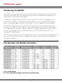
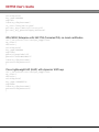
Part Numbers and Model Information
CCD = Linear Imager
2D = Omni-directional Imager with 2-Dimensional decoding
1-2
KDT750 User’s Guide
Warranty Information
A one-year warranty against material defects and workmanship from the date of shipment
is guaranteed by AML. Products are sold on the basis of specifications applicable at the
time of manufacture. AML shall have no obligation to modify or update products once sold.
At our option, we will repair or replace, at no charge, any unit that proves to be defective
providing the appropriate steps are taken to procure an RMA (Return Materials
Authorization) number and shipping instructions from AML.
Agency Compliance
FCC Declaration of Conformity
Product Name: Model KDT750 Price Verification System
Model Number: KDT750
This equipment complies with Part 15 of the FCC Rules. Operation is subject to the following
two conditions: (1) This equipment may not cause harmful interference, and (2) this equipment must accept any interference received, including interference that may cause undesirable operation.
This equipment has been tested and found to comply with the limits for a Class A digital
device, pursuant to Part 15 of the FCC Rules. These limits are designed to provide reasonable protection against harmful interference when the equipment is operated in a residential environment. This equipment generates, uses and can radiate radio frequency energy,
and if not installed and used in accordance with the instructions, may cause harmful interference to radio communications. However, there is no guarantee that interference will not
occur in a particular installation. If you determine the equipment does cause harmful interference to radio or television reception (this may be determined by monitoring the interference while turning the equipment off and on), you are encouraged to try to correct the
interference by one of the following measures:
1-3
KDT750 User’s Guide
·
·
·
·
·
Reorient or relocate the receiving antenna.
Increase the separation between the equipment and receiver.
Connect the equipment into an outlet on a circuit different from that to which the
receiver is connected.
Consult the dealer or an experienced radio or TV technician for help.
1-4
KDT750 User’s Guide
Getting Started
This chapter gives a quick start
introduction to using the KDT750.
2-1
KDT750 User’s Guide
KDT750 Startup Sequence
The KDT750 unit will begin booting the operating system once power is applied to the terminal and the rear panel is completely closed.
NOTE: The rear panel must be in place before the unit will power up.
Once powered on, the KDT750 will automatically start the configured boot application.
From the factory, the unit will load default configuration settings and boot into the KDT750
home desktop.
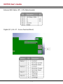
Entering System Setup
The KDT750 System Setup can be accessed by pressing the two outer pushbuttons (“A” and
“D”) at the same time. After a brief delay, the unit will enter into setup mode.
NOTE: When using the KDT750 home Desktop as the boot application, the System Setup
application can also be accessed through the Settings menu.
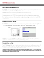
Navigating Setup
The KDT750 Setup Utility uses a simple menu interface for all system configuration options. To
access a KDT750 configuration sub-menu, tap the name of the menu with a plastic stylus.
To modify a configuration value, tap the option's name.
When in System Setup, the KDT750 unit will automatically reboot if there is no user activity for
5 minutes. This prevents unauthorized access into the configuration options in the event that
the operator left the unit in setup mode.
2-2
KDT750 User’s Guide
Once setup is complete, the < Save & Reboot > option must be selected to write the configuration settings to the system memory.
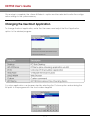
Changing the User Boot Application
To change the boot application, enter the User menu and adjust the Boot Application
option to the desired program.
A custom application can be executed by selecting the Custom option and entering the
full path to the program with the touchscreen keypad.
2-3
KDT750 User’s Guide
Terminal Overview
This chapter describes the KDT750 terminal
hardware and details internal and external
cable connections.
3-1
KDT750 User’s Guide
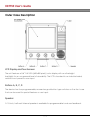
Outer Case Description
LCD Display and Touchscreen
The unit features a 5.6” Full VGA (640x480 pixels) color display with an ultra-bright
backlight for an unsurpassed level of viewability. The LCD is bonded to an industrial rated,
resistive touch panel for user input.
Buttons A, B, C, D
The device has four programmable, momentary pushbutton type switches on the front case
that can be used for special features or user input.
Speaker
A 1.5 inch, half-watt internal speaker is available for programmable tonal user feedback.
3-2
KDT750 User’s Guide
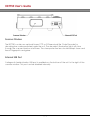
Scanner Window
The KDT750 contains an optional Linear CCD or 2-Dimensional Bar Code Decoder for
decoding bar codes presented under the unit. The decoder's illumination lights will shine
through the scanner window at all times. The clear protective lens should be kept clean and
free of fingerprints and grime.
External USB Port
A diagnostic/administration USB port is available on the bottom of the unit to the right of the
scanner window. This port can be disabled internally.
3-3
KDT750 User’s Guide
Case Mounting Tabs & Case Mounting Screws
The KDT750 main outer case is held closed on the left side by two #4-40 x 1/4” screws.
Longer screws should not be used, as damage to the internal components of the KDT750
can result. Then right side of the outer case contains three slots that the matching tabs of
the rear panel should slide into.
Rear Panel Description
The rear panel of the unit is made from high quality 1/16” stainless steel. The panel secures
the internal connections, seals the unit from dust and debris, and prevents vandalism and
unauthorized access.
3-4
KDT750 User’s Guide
Opening the KDT750 Outer Case
In order to open the KDT750, remove the two screws on the left side and slightly rotate the
outer case to the right. Once the unit is opened approximately one inch, the outer case
can be slid off of the mounting tabs. All mounting brackets will remain with the rear panel,
and the electronics and wiring will stay attached to the outer case.
3-5
KDT750 User’s Guide
Internal Connections
Connections to the KDT750 unit are housed internally to prevent vandalism and to secure
the device.
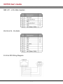
Internal Connector Pinouts
Weigand (J3 – 4 Pin Male Header)
3-6
KDT750 User’s Guide
MSR (JP1 – 6 Pin Male Header)
RS-232 (J9 8 - Pin RJ45)
RJ-45 to DB9 Wiring Diagram
3-7
KDT750 User’s Guide
External USB Cable (JP2 - 5 Pin Male Header)
Digital I/O (J14-J17 - Screw Terminal Block)
3-8
KDT750 User’s Guide
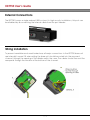
External Connections
The KDT750 houses a single external USB host port. In high security installations, this port can
be disabled by disconnecting the internal cable from the port header.
Wiring Installation
To prevent vandalism and unauthorized use, all major connections to the KDT750 base unit
are internally housed. All wires exiting the base unit should be routed into the recessed
channel, through the opening of the divider wall in the case. The cables should then exit the
rear panel through the window at the bottom of the channel.
3-9
KDT750 User’s Guide
Power Requirements and Battery Information
The KDT750 can utilize three power sources: external DC power supply, Power-over-Ethernet
and an optional internal backup battery.
External DC Power Supply
NOTE: Using power supplies that are not approved by AML for use with the KDT750 unit can
cause damage to the unit and will void all warranties.
Internal Power-over-Ethernet Supply
The KDT750 contains a 802.3af compatible power supply. The unit can be powered via category 5 networking cable when used with an 802.3af compatible power injector. Both network data traffic and power can be sent via the same category 5 wire.
3 - 10
KDT750 User’s Guide
Optional Backup Battery
If the KDT750 unit is equipped with an optional internal backup battery, the unit will continue
to operate when all other power sources are lost. Depending on the configuration and
usage, the backup battery should enable the unit to operate for approximately one hour.
When power is applied to the unit, the backup battery will be automatically charged. After
a complete discharge, the backup battery should be charged 48 hours before use.
NOTE: The backup battery is permanently connected to the KDT750 motherboard. Do not
attempt to remove the battery. The KDT750 unit must be properly disposed of and the battery recycled when it has reached the end of its usable life.
3 - 11
KDT750 User’s Guide
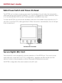
Main Power Switch and Power-On Reset
The KDT750 unit contains a main power switch that disables the unit when the rear panel is
removed during servicing and installation. This switch is designed as a safety measure, and it
is not recommended that the switch be bypassed or modified in any way.
To reset the KDT750 unit with power enabled, hold down the middle two pushbuttons for 10
seconds or until the LCD screen goes black. When the buttons are released, the unit will perform a warm boot.
Secure Digital (SD) Card
The internal SD card is required for normal operation of the KDT750 unit. The card can be
removed and connected to a PC for configuration, upgrades and file transfer, but the
device should not be powered on without it properly installed and secured.
All KDT750 configuration files are located on the SD card.
3 - 12
KDT750 User’s Guide
Communications & Input
This chapter describes the communication
capabilities of the KDT750.
4-1
KDT750 User’s Guide
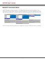
Network Communications
The KDT750 relies on either the built-in 10/100 BaseTX Fast Ethernet network adapter or the
optional 802.11b/g/n wireless radio for communicating with a host server. General network settings and device selection is made through the network.settings file or the KDT750 Setup Utility.
NOTE: All wireless SECURITY settings are configured in the wifi.conf file described in Chapter 5.
4-2
KDT750 User’s Guide
Example network.settings (Only using Ethernet with DHCP)
eth_enable=1
eth_dhcp=1
wifi_enable=0
Example network.settings (Only using Ethernet with Static Addressing)
eth_enable=1
eth_dhcp=0
eth_ip=192.168.100.101
eth_subnet=255.255.255.0
eth_gateway=192.168.100.1
wifi_enable=0
dns=192.168.100.2
4-3
KDT750 User’s Guide
Example network.settings (Only using 802.11 Radio with DHCP)
eth_enable=0
wifi_enable=1
wifi_dhcp=1
Serial Communications
The KDT750 contains two user accessible RS-232 ports and one bar code scanner port for
serial communications with a PC or other peripheral devices. Each port is capable of baud
rates up to 115.2 Kbps.
Serial communication ports are used to communicate with devices such as:
•
•
•
•
•
Internal Bar Code Scanner
External Bar Code Scanner
External Magnetic Stripe Reader
Serial Printer
PC
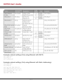
The serial.settings file is used to configure the three RS-232 serial ports on the KDT750. Each
port is designed for a specific function and may or may not be used deepening on the
KDT750's hardware configuration:
The serial ports can be configured from the Driver menu of setup. The ports will be configured with these settings on boot.
4-4
KDT750 User’s Guide
4-5
KDT750 User’s Guide
Example serial.settings (Linear CCD Scan Engine, Debug Console on Port 1)
port0baud=9600
port1baud=115200
port1console=1
port1bits=8
port1parity=N
port1stop=1
port2baud=9600
port2bits=8
port2parity=N
port2stop=1
Example serial.settings (2D Omni-directional Imager Scan Engine)
port0baud=9600
port1baud=115200
port1console=0
port1bits=8
port1parity=N
port1stop=1
port2baud=9600
port2bits=8
port2parity=N
port2stop=1
USB Communications
The unit contains three user accessible USB 1.1 Full speed host ports, capable of data rates
up to 12 Mbps.
Common USB devices that can be used with the KDT750 are:
•
•
•
•
External Bar Code Scanner
External Magnetic Stripe Reader
External Keyboard
USB storage devices (“thumb” or “pen” drives)
No configuration is necessary for USB devices that are compatible with the KDT750.
4-6
KDT750 User’s Guide
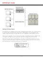
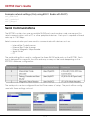
Digital I/O
The KDT750 base unit contains two electrically isolated digital inputs and two electrically isolated digital outputs.
Digital Outputs (Micro-Relays)
The KDT750 digital outputs are controlled via internal micro-relays driven by the microprocessor. These relays can be used to drive external devices such as:
•
•
•
•
Lights and Beacons
Door Strikers
Sirens
Stationary Scanners
The internal relays are designed for low voltage applications. To use the relays in high voltage situations, an additional external rely should be implemented.
4-7
KDT750 User’s Guide
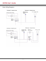
Relay Wiring Diagrams
4-8
KDT750 User’s Guide
Digital Inputs (Opto-Isolators)
The KDT750's internal digital inputs can be used to signal events and actions from an external source. Possible uses for the isolated input are:
• External Pushbutton Switches
• Door Sensors
• Proximity Sensors
Digital Input Wiring Diagram
Weigand Interface
The Weigand interface is used to connect proximity card and smart card readers to the
KDT750. Weigand is a simple, two-wire interface used to transmit unidirectional data from a
peripheral device to a host.
4-9
KDT750 User’s Guide
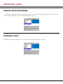
Software Keyboard Wedge
A software keyboard wedge can be used to convert data coming from one or more external hardware devices into a usable keyboard input.
Pushbutton Input
The KDT750 panel pushbuttons can emulate PC keyboard key presses.
4 - 10
KDT750 User’s Guide
Wireless Networking
This chapter describes the configuration
of the optional internal 802.11 radio.
5-1
KDT750 User’s Guide
Overview
The KDT750 terminal can contain an optional 802.11b/g/n radio and internal antenna. This
radio is specifically designed to communicate with any 802.11b/g or 802.11n (Draft v2.0)
Access Point.
The range of the radio depends greatly on the quality of the Access Point and the RF communications characteristic of the environment where the device is used. The typical range
for an 802.11 radio is 500 feet through free air. Additional Access Points must be added to
improve coverage in a larger area, or in electrically noisy RF environments.
802.11 Fallback
Wireless LAN technology is designed to make maintaining a connection between two
devices as reliable and consistent as possible. Since the speed of the connection between
wireless devices will vary as range and signal quality varies, the wireless devices will intentionally sacrifice throughput (data rate or connection speed as measured in bits per second) in exchange for maintaining a reliable connection. In other words, a reliable connection at a lower speed is preferred over an unreliable connection at a higher speed (i.e., it is
easier to maintain the connection if data rate is deliberately reduced, or put another way,
lower data rates will tolerate a higher range and/or worse signal quality). This characteristic
is known as fallback. As example, an 802.11b system will fallback from 11 Mbps to 5.5 Mbps
as range increases or signal quality decreases. Subsequent fallbacks from 5.5 Mbps to 2
Mbps and 1 Mbps are also supported.
5-2
KDT750 User’s Guide
Interference and Coexistence
802.11 operates in a range of radio frequencies known as an "unlicensed" band (i.e., the
FCC does NOT require the use of a license in order to operate a radio transmitter in this
range). This means that commercially available radio devices other than wireless LAN
devices are permitted to use the same frequency band as 802.11. Consequently, these coexisting radio devices can interfere or "jam" the wireless LAN (and vice versa). The most troublesome devices are cordless telephones and microwave ovens.
Fortunately, higher quality cordless phones tend to "listen" for a clear channel before
becoming active and will thus avoid interfering with a wireless LAN (i.e., the cordless phone
seeks a clear channel for itself so naturally avoids being interfered with or being a source of
interference). Jamming from microwave ovens is more severe but is usually restricted to the
upper frequency range for 802.11 (it should be noted that 802.11b/g divides the available
frequency band into 11 channels [US]. The higher numbered channels are most susceptible
to microwave oven interference).
In each instance, jamming occurs only when the cordless telephone or microwave oven is
active.
Encryption and Authorization
Much has been publicized in the mass media recently about security problems with wireless
LANs. Although it cannot be denied that some encryption algorithms currently used in
802.11 are flawed, the fact is that security breaches of a wireless LAN require a deliberate
attempt to access the network by an intruder.
The primary issue is that many current users of wireless LAN have opted NOT to turn on security features. If users were to enable the security features currently available (including only
allowing known systems access to the network and enabling WEP [Wired Equivalent Privacy]
or WPA [Wifi Protected Access]) on even the most basic access points, the intruder's work is
much harder. Much as a burglar will stray away from a house whose doors and windows are
securely locked, so too will an attacker tend to move past a wireless network when even
the simplest security measures are enabled.
Wireless Configuration
The optional 802.11b/g/n radio can be configured with the KDT750 Setup Utility under the
Network menu.
5-3
KDT750 User’s Guide
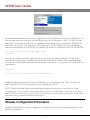
Some advanced features are not configurable with the utility and manual configuration of
the settings may be necessary by editing the wifi.conf configuration file. This file is a standard ASCII encoded text file that is readable and writable by any text editor. Empty lines
and lines starting with a # character will be ignored. The file begins with two mandatory
definition parameters that MUST be included in all wireless configuration files for the KDT750:
ctrl_interface=/var/run/wpa_supplicant
ap_scan=1
This tells the wireless security supplicant how to set up the radio interface. The file then
includes a network block header that will be followed by all wireless network parameters
and security settings that should be used by the connection. A close brace '}' will follow the
parameters:
network={
<<<List of 802.11 configuration parameters>>>
}
Multiple valid network blocks can be defined in the configuration file. The unit will try all
valid network blocks until the device is associated with an AP.
NOTE: Care should be taken when defining multiple network blocks because in some
configurations it is possible to associate with an AP but not be able to transmit or receive
data. In these cases, the unit will not know to move on to the next network block because
the radio sees a valid association with the AP.
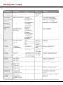
Wireless Configuration Parameters
Inside a network block of the configuration file will be all the necessary parameters to configure the interface.
5-4
KDT750 User’s Guide
5-5
KDT750 User’s Guide
5-6
KDT750 User’s Guide
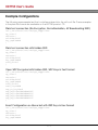
Example Configurations
The following are example text that could be entered into the wifi.conf file. These examples
in the plain file format are available on the KDT750 product CD.
Plain text connection (No Encryption, No Authorization, AP Broadcasting SSID)
ctrl_interface=/var/run/wpa_supplicant
ap_scan=1
network={
ssid="MySSID"
key_mgmt=NONE
}
Plain text connection with hidden SSID
ctrl_interface=/var/run/wpa_supplicant
ap_scan=1
network={
ssid="MySSID"
key_mgmt=NONE
scan_ssid=1
}
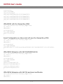
Open WEP Encrypted with hidden SSID, WEP Keys in Text Format
ctrl_interface=/var/run/wpa_supplicant
ap_scan=1
network={
ssid="MySSID"
key_mgmt=NONE
scan_ssid=1
auth_alg=OPEN
wep_tx_keyidx=0
wep_key0="MYTEXTWEPKEY0"
wep_key1="MYTEXTWEPKEY1"
wep_key2="MYTEXTWEPKEY2"
wep_key3="MYTEXTWEPKEY3"
}
Exact Configuration as Above but with WEP Keys in Hex Format
ctrl_interface=/var/run/wpa_supplicant
ap_scan=1
network={
ssid="MySSID"
key_mgmt=NONE
5-7
KDT750 User’s Guide
scan_ssid=1
auth_alg=OPEN
wep_tx_keyidx=0
wep_key0=4D59544558545745504B455930
wep_key1=4D59544558545745504B455931
wep_key2=4D59544558545745504B455932
wep_key3=4D59544558545745504B455933
}
WPA/WPA2 with Pre-Shared Key (PSK)
ctrl_interface=/var/run/wpa_supplicant
ap_scan=1
network={
ssid="MySSID"
key_mgmt=WPAPSK
psk=”123456789”
}
Exact Configuration as Above but with raw Pre-Shared Key (PSK)
ctrl_interface=/var/run/wpa_supplicant
ap_scan=1
network={
ssid="MySSID"
key_mgmt=WPAPSK
psk=469100a17577fd350ac9e09acd2399b56145e76a22b8183ff311f1c207c93d3a
}
WPA/WPA2 Enterprise with EAP-PEAP/MSCHAPv2]
ctrl_interface=/var/run/wpa_supplicant
ap_scan=1
network={
ssid="MySSID"
key_mgmt=WPAEAP
eap=PEAP
phase1="peaplabel=0"
phase2="auth=MSCHAPV2"
identity="MyUsername"
password="MyPassword"
}
WPA/WPA2 Enterprise with EAP-TLS and local certificates
ctrl_interface=/var/run/wpa_supplicant
ap_scan=1
network={
5-8
KDT750 User’s Guide
ssid="MySSID"
key_mgmt=WPAEAP
eap=TLS
identity="MyUsername"
ca_cert="/mnt/sd/ca.pem"
private_key="/mnt/sd/client.p12"
private_key_passwd="MyKeyPassword"
}
WPA/WPA2 Enterprise with EAP-TTLS (Tunneled TLS), no local certificates
ctrl_interface=/var/run/wpa_supplicant
ap_scan=1
network={
ssid="MySSID"
key_mgmt=WPAEAP
eap=TTLS
phase1="peaplabel=0"
phase2="auth=MSCHAPV2"
identity="MyUsername"
password="MyPassword"
}
Cisco Lightweight EAP (LEAP) with dynamic WEP keys
ctrl_interface=/var/run/wpa_supplicant
ap_scan=1
network={
ssid="MySSID"
key_mgmt=IEEE8021X
eap=LEAP
identity="MyUsername"
password="MyPassword"
}
5-9
KDT750 User’s Guide
Integrated Bar Code
Scanner
This chapter describes the use of the
internal bar code reader.
6-1
KDT750 User’s Guide
Overview
The KDT750 terminals can contain an integrated bar code reader for decoding bar code
symbols in a variety of formats.
The terminal can be equipped with a linear CCD bar code decoder, a 2-Dimensional,
Omni-directional decoder or no bar code scan engine at all.
It is important to know what type of engine is installed in the unit to allow for correct customization of the engine.
Determining Scanner Type
The type of the internal scanner can be determined either by the KDT750's model number
reference chart at the beginning of this document or by observing the scanner's decode
pattern.
If the KDT750 model number ends in a zero, the unit contains no internal scan engine:
KDT750-xxx0
If the KDT750 model number ends in a one, the unit contains the Linear CCD laser:
KDT750-xxx1
If the KDT750 model number ends in a two, the unit contains the 2D Omni-directional imager:
KDT750-xxx2
If the KDT750 model number ends in a three, the unit contains the 1D Laser engine:
KDT750-xxx3
If the KDT750 model number ends in a four, the unit contains the External Omni-directional engine:
KDT750-xxx4
6-2
KDT750 User’s Guide
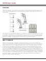
Linear CCD Decode Zones
The Linear CCD can only read symbols that are within its field of view:
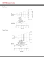
2D Omni Scanner Aiming System and Decode Zones
The 2D Omni-directional scanner will use a 650nm laser to draw an aiming pattern of the
decoder's decode zone:
The decoder is only capable of decoding symbols that are within its field of view. Two focus
modes are selectable for the 2D imager:
6-3
KDT750 User’s Guide
Far Focus:
Near Focus:
6-4
KDT750 User’s Guide
Triggering
The KDT750's internal bar code scanners are designed to be used in presentation modes. In
these modes, the scanner is always scanning and looking for bar codes to decode.
NOTE: Some internal scanners have the ability to disable the illumination LEDs when no bar
code is present under the scanner. The scanner is still looking for bar codes, but is saving
power by only enabling the illumination when a new bar code symbol is present.
To manually trigger the bar code decoder, use the Data Viewer tool under the System Tools
folder.
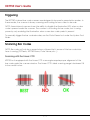
Scanning Bar Codes
NOTE: Bar codes will only be scanned when software that is aware of the bar code interface is running (PCDemo, KDT750 Demo, Data Viewer, etc...)
Scanning with the Linear CCD
KDT750 units equipped with the Linear CCD scan engine require proper alignment of the
bar code under the scanner window. The Linear CCD's ideal scanning range is between 2.5
inches and 8 inches.
6-5
KDT750 User’s Guide
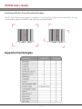
Scanning with the Omni-Directional Imager
The 2D Omni-directional imager is capable of scanning bar codes at any orientation as long
as the entire symbol is visible to the scanner and illuminated.
Supported Symbologies
6-6
KDT750 User’s Guide
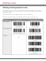
Obtaining and Using Setup Bar Codes
The internal bar code scanners can be configured with special setup bar code symbols.
These symbols are specific to the model of bar code scanner installed in the unit and are
available from AML.
The default parameters and trigger mode bar codes are listed below.
NOTE: The unit will NOT make an audible beep after scanning a setup bar code.
6-7
KDT750 User’s Guide
Installed Software
This chapter describes the preinstalled
software suite on the KDT750.
7-1
KDT750 User’s Guide
PCDemo
PCDemo is a versatile client application designed to run natively on the AML KDT750 price
checking unit. PCDemo handles data capture and processing, network communication
with a database server, and all user interface and display attributes for data lookup and
verification applications.
More information on PCDemo can be found by viewing the KDT750 APL Guide. See the
Related Documents section in Chapter 1 for more information.
KDT750 Demo
The KDT750 Demo application is a standalone demo of the capabilities of the KDT750. It is
based on the PCDemo software, but requires no network or external database. Internally, it
includes a small number of bar codes that can be scanned to simulate a database lookup.
7-2
KDT750 User’s Guide
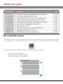
Bar Code Data Viewer
The KDT750 contains a simple application called Data Viewer that demonstrates and verifies
the configuration of various input devices. Data Viewer is located in the System Tools folder.
Data Viewer displays a field for each of the standard input devices:
• Internal Bar Code Reader
• External Magnetic Stripe Reader
• External Proximity Card Reader
7-3
KDT750 User’s Guide
Web Browser
The KDT750 includes Links2, a built-in HTTP web browser for fetching and displaying web
pages. The application's icon is located under the Network folder.
Links2 capabilities include:
•
•
•
•
•
•
•
HTML 4.0 support (without CSS)
HTTP 1.1 support
HTTPS (SSL) support
Text or graphical mode
Tables and frames in both modes
Bookmarks
Background file downloads
Graphics Mode
7-4
KDT750 User’s Guide
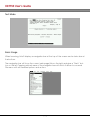
Text Mode
Basic Usage
When browsing, Links2 displays a navigation bar at the top of the screen and a status bar at
the bottom.
The navigation bar will show the current web page title on the right and give a “Back” button on the left. Tapping a blank area of the navigation bar will switch the bar to a normal
File menu with all standard options and actions.
7-5
KDT750 User’s Guide
On-Screen Keyboard
The unit includes a simple on-screen keyboard for use when no other input is available.
VT100/220 Terminal Emulator
The KDT750 contains a simple telnet client capable of emulating VT100 and VT220 terminals.
7-6
KDT750 User’s Guide
Mechanical Integration
and Mounting
This chapter describes methods to mount
the KDT750 unit in a variety of environments.
8-1
KDT750 User’s Guide
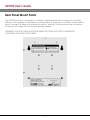
Rear Panel Mount Points
The KDT750 base unit is backed by a stainless steel rear panel with a variety of mounting
patterns. Each pattern is indicated by the rear label. A sharp punch or knife can be used to
punch through the label at the desired locations, and only the necessary holes should be
knocked out to keep the unit environmentally sealed.
WARNING: THE REAR PANEL SHOULD BE REMOVED FROM THE OUTER CASE BEFORE
PUNCHING ANY HOLES IN THE LABEL.
8-2
KDT750 User’s Guide
Flush Wall Mounting
The KDT750 base unit can be flush mounted with four screws via four holes in the rear panel
(two “key-hole”, two round). The rear panel's cable inlet is recessed, allowing for flush
mounting in certain situations.
8-3
KDT750 User’s Guide
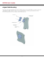
Angled Wall Mounting
The optional Angled Wall Bracket (ACC-0752) hard mounts the KDT750 to any flat surface at
a 20 degree angle, ideal for price checking applications. The bracket attaches to the
KDT750's rear panel via four stainless steel studs and nuts.
8-4
KDT750 User’s Guide
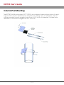
Column/Post Mounting
The KDT750 Pole Mount bracket (ACC-0750) is a non-destructive mounting solution for existing round structural or aesthetic posts and poles. By utilizing nylon or steel straps, the unit
can be mounted to poles ranging in sizes from 4 to 24 inches in diameter. The ideal pole
diameter for the bracket ranges from 6 to 16 inches.
8-5
KDT750 User’s Guide
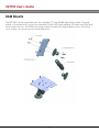
RAM Mounts
The KDT750 can be mounted with the standard “B” size RAM® Mounting system. The rear
panel of the base unit houses the standard 4 hole AMPS bolt pattern for attaching RAM ball
and socket mounts. The RAM mounting system includes fully adjustable mounts, as well as
locks, bases, accessory mounts and extensions.
8-6
KDT750 User’s Guide
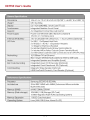
Appendix A
Technical Specifications
A-1
KDT750 User’s Guide
A-2
KDT750 User’s Guide
A-3
KDT750 User’s Guide
Appendix B
Wireless Reference Table
B-1
KDT750 User’s Guide
B-2
KDT750 User’s Guide
B-3
KDT750 User’s Guide
B-4