1
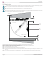
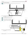
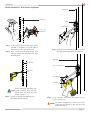
INSTALLATION INSTRUCTIONS
FLIP
Flip-Down LCD Mount
NORTH AMERICA
3130 East Miraloma Avenue
Anaheim, CA 92806 USA
USA and Canada –
Phone: 800-368-9700
Fax: 800-832-4888
Other Locations – Phone: (001)-714-632-7100; Fax: (001)-714-632-1044
©Premier Mounts 2009
9531-017-011-00
EUROPE
Swallow House,
Shilton Industrial Estate,
Shilton, Coventry, England CV79JY
Phone: +44 (0) 2476 614700
Fax: +44 (0) 2476 614710
FLIP Mount
Table of Contents
Warning Statements
Parts List
Installation Tools
FLIP Mount Location
Hardwood Cabinet Installation
Softwood Cabinet Installation
Mount Installation - Wall Surface (Optional)
Attaching the Flat Panel
FLIP Mount Adjustments
Final Adjustments
Technical Specifications
Warranty
2
3
3
4
5
6
7
8
9
9
10
11
Warning Statements
PRIOR TO THE INSTALLATION OF THIS PRODUCT, THE INSTALLATION INSTRUCTIONS SHOULD BE READ AND
COMPLETELY UNDERSTOOD. THE INSTALLATION INSTRUCTIONS MUST BE READ TO PREVENT PERSONAL INJURY AND
PROPERTY DAMAGE. KEEP THESE INSTALLATION INSTRUCTIONS IN AN EASILY ACCESSIBLE LOCATION FOR FUTURE
REFERENCE.
PREMIER MOUNTS DOES NOT WARRANT AGAINST DAMAGE CAUSED BY THE USE OF ANY PREMIER MOUNTS
PRODUCT FOR PURPOSES OTHER THAN THOSE FOR WHICH IT WAS DESIGNED OR DAMAGE CAUSED BY UNAUTHORIZED
ATTACHMENTS OR MODIFICATIONS, AND IS NOT RESPONSIBLE FOR ANY DAMAGES, CLAIMS, DEMANDS, SUITS,
ACTIONS OR CAUSES OF ACTION OF WHATEVER KIND RESULTING FROM, ARISING OUT OF OR IN ANY MANNER RELATING TO ANY SUCH USE, ATTACHMENTS OR MODIFICATIONS.
THE WALL STRUCTURE MUST BE CAPABLE OF SUPPORTING AT LEAST 5 TIMES THE WEIGHT OF THE FLAT PANEL. IF
NOT, THE WALL STRUCTURE MUST BE RE-INFORCED. PROPER INSTALLATION PROCEDURE BY A QUALIFIED SERVICE
TECHNICIAN, AS OUTLINED IN THE INSTALLATION INSTRUCTIONS, MUST BE ADHERED TO. FAILURE TO DO SO COULD
RESULT IN SERIOUS PERSONAL INJURY, OR EVEN DEATH.
SAFETY MEASURES MUST BE PRACTICED AT ALL TIMES DURING THE INSTALLATION OF THIS PRODUCT. USE PROPER
SAFETY GEAR AND TOOLS FOR THE INSTALLATION PROCEDURE TO PREVENT PERSONAL INJURY.
Indicates that the power plug is to be disconnected
from the power outlet.
Contact Premier Mounts with any questions (800) 368-9700.
Safety precautions must be taken at all times.
Warning and Caution statements.
It is recommended that a maximum of 5/8” plaster board be used when mounting to wooden studs.
Do not install on a structure that is prone to vibration, movement or chance of impact. Failure to do so could result in damage to the flat panel
and/or damage to the mounting surface.
Do not install near heater, fireplace, direct sunlight, air conditioning or any other source of direct heat energy. Failure to do so may result in
damage to the flat panel and could increase the risk of fire.
At least two qualified people should perform the installation procedure. Injury and/or damage can result from dropping or mishandling the
flat panel.
Page 2
Installation Instructions
FLIP Mount
Parts List
Congratulations on the purchase of your new Premier Mounts FLIP flat panel mount. This mount is shipped with all
proper installation hardware and components. Make sure that none of these parts are missing and/or damaged before
beginning installation. If there are parts missing and/or damaged, please stop the installation and contact Premier Mounts
(800) 368-9700.
The M5 flat head screw will prevent
the FLIP mount mounting plate from
rotating 360°.
M5 x 10mm Flat Head Screw (Qty 1)
1/4-20 x 5/8” Combo Screw (Qty 2)
1/4-20 Tee Nut (Qty 2)
M4 x 10mm Combo Screw (Qty 4)
#14 x 7/8” Wood Screw (Qty 2)
Under-counter Applications
#14 x 2” Wood Screw (Qty 2)
Wall Stud Applications
5/32” Allen Wrench
Flip Mount (Qty 1)
Installation Tools (not supplied)
5/16” Drill Bit
1/8” Drill Bit
(Tee Nut Installation)
(Wood Stud Installation)
Tape
Measure
Installation Instructions
Pencil
Electronic Stud Finder
Drill
Hammer
Screwdriver
Page 3
FLIP Mount
FLIP Mount Location
Before drilling, make sure that there is enough room to lower and raise the display. For example, when the display is put in
the “up” position, it should not hit the wall and should be even with the front of the cabinet.
Mount placement will be primarily determined by the size of the flat panel being used.
There must be enough clearance for the FLIP mount and flat panel to be adjusted without interfering with the wall, counter
top surface and the overhead cupboard (see diagram below).
Clearance
Cupboard
Clearance
“UP” Position
FLIP
Mount
Flat
Panel
“DOWN” Position
Clearance
Counter top
When mounting the FLIP mount to the underside of a cupboard, careful consideration must be taken.
The following steps will help in determining the placement of the FLIP mount (please see diagram above):
Step 1. Attach the flat panel to the FLIP mount (SEE PAGE 8).
Step 2. Put the FLIP mount in the “up” position.
Step 3. Place the FLIP mount base flush on the underside of the cupboard.
Step 4. Slide flat panel and FLIP mount to the rear of the cupboard surface until the bottom edge of the flat panel is a minimum 1” from
the wall.
Step 5. Use a pencil to mark where the two mounting holes are. This will be the location where your pilot holes will be drilled.
Page 4
Installation Instructions
FLIP Mount
Hardwood Cabinet Installations
Wood screws are recommended when mounting the FLIP mount onto hardwood surfaces.
Cupboard
FLIP
Mount
This distance was
determined in the
FLIP Mount Location
section.
Step 1. Place the FLIP Mount base on the mounting
location and mark (using a pencil) where the FLIP
will be mounted.
The FLIP mount base may be used as a
template when marking the mount location.
Prior to drilling into the underside of the
cabinet, it is strongly recommended that
all items be removed from the cabinet.
Marking
1/8” Drill
Bit
Drill
Step 2. Using a 1/8” drill bit and portable
drill, pre-drill both pilot holes at the
marked locations.
Installation Instructions
Page 5
FLIP Mount
Step 3. Line the FLIP Mount up with the two
pre-drilled mounting holes and use
two (2) #14 x 7/8” wood screws and
secure the FLIP Mount to the underside
of the cabinet using a screwdriver.
Do NOT over-tighten the wood
screws, as this could cause the
threads to strip out the wood
inside the cabinet enclosure.
#14 x 7/8” Wood
Screw
FLIP Mount
Screwdriver
Softwood Cabinet Installation
1/4-20 Tee Nut and screws are recommended when installing the FLIP mount into softwood surfaces.
1/4-20 Tee
Nut
1/4-20 Tee
Nut
1/4-20 x 5/8”
Screw
Cupboard
Pre-drilled
Hole
(5/16” drill
bit)
FLIP Mount
Screwdriver
Step 1. Use a 5/16” drill bit and drill to pre-drill the tee nut pilot holes in the underside of the cupboard.
Step 2. After drilling the mounting holes, open the cupboard door and place two (2) 1/4 - 20 tee nuts into each hole (see inset above).
Use a hammer to gently tap into place.
Step 3. Line the FLIP Mount up with the two pre-drilled mounting holes.
Step 4. Using a screwdriver, insert and tighten two (2) 1/4 - 20 x 5/8” screws and attach the FLIP Mount to the underside of the
cabinet.
Page 6
Installation Instructions
FLIP Mount
Mount Installation - Wall Surface (Optional)
Wall Stud
Wall Stud
Mark
FLIP Mount
Electronic
Stud Finder
Step 1. If the location where the flat panel will be
installed is acceptable, use a stud finder to
determine the exact center of each stud.
Step 2, Once a wood stud has been located, mark
this spot with a pencil. This will be the upper
mounting point.
Step 3. Mark the lower mounting point as well, once
the upper mounting point has been marked.
Wall Stud
Wall Stud
#14 x 2” Wood Screw
1/8” Drill
Bit
FLIP Mount
Screw driver
Before drilling the pilot holes, line
up the mounting holes with the
pencil marks and level the FLIP
mount, if needed.
Step 4. Using a 1/8” drill bit, pre-drill both pilot
holes at the marked locations.
Step 5. Using a portable drill, insert and tighten two (2)
#14 x 2” wood screws.
Do NOT over-tighten the wood screws, as this
could cause the threads to strip out the wood
inside the wall stud.
Installation Instructions
Page 7
FLIP Mount
Attaching the Flat Panel
If you chose not to use the 360° feature of the FLIP mount, please insert and tighten one (1) M5 x 10mm flat head screw
into any one of the four mounting point locations (please see below for mounting points). The M5 x 10mm flat head screw
will prevent the FLIP mount from rotating 360°.
FLIP Mount
Keyhole Mounting
Slot
M4 x 10mm
Screw
M5 x10mm Flat Head Screw (see NOTE:)
M4 x 10mm
Screw
Mounting Point
Flat Panel
If you chose not to use the 360° feature of the FLIP mount, please insert and tighten one (1) M5 x 10mm flat head screw
into any one of the four mounting point locations (please see above for mounting points). The M5 x 10mm flat head screw
will prevent the FLIP mount from rotating 360°.
Step 1.
Step 2.
Step 3.
Step 4.
Step 5.
Step 6.
Page 8
Locate the mounting points that are on the back of the flat panel.
Line up the mounting points on the flat panel with the corresponding mounting holes on the FLIP mount.
Loosely attach the upper two (2) M4 x 10 mounting screws.
Insert the screw heads into the corresponding keyhole mounting slots that are on the FLIP mount.
With the FLIP mount securely attached, insert and tighten the two (2) lower M4 x 10 mounting screws.
Use a screwdriver to tighten all mounting hardware at this time.
Installation Instructions
FLIP Mount
FLIP Mount Adjustments
Vertical Adjustment
360° Rotation Adjustment
Left-to-Right 360° Rotation
Adjustment
Final Adjustments
The FLIP mount has pivots points that
allow the mount to be easily adjusted. Once
the adjustments have been made, the pivot
points will need to be tightened. Please refer
to the steps below to tighten the pivot point
screws.
Step 1. Make sure the FLIP mount has
been adjusted to the determined
viewing angle.
Step 2. Locate each pivot point.
Step 3. Use the 5/32” Allen wrench
(supplied) to tighten each pivot
point screw.
Pivot Point
Tilt Adjustment
Pivot Point
Screw
5/32” Allen
Wrench
5/32” Allen
Wrench
Pivot Point
Screw
Vertical/Lateral
Adjustment
Pivot Point
Installation Instructions
Page 9
FLIP Mount
Technical Specification
All measurements are in inches [mm].
Page 10
Installation Instructions
FLIP Mount
Warranty
PREMIER MOUNTS
LIMITED LIFETIME WARRANTY
What and Who is Covered by this Limited Warranty and for How Long
Premier Mounts warrants this product to be free from defects in material and workmanship for the lifetime of
the original owner of this product. The limited warranty is valid only for the original purchaser of the product.
What Premier Mounts Will Do
At the sole option of Premier Mounts, Premier Mounts will repair or replace any product or product part that is
defective. If Premier Mounts chooses to replace a defective product or part, a replacement product or part will
be shipped to you at no charge, but you must pay any labor costs.
What is Not Covered; Limitations
PREMIER MOUNTS DISCLAIMS ANY LIABILITY FOR DAMAGE TO MOUNTS, ADAPTERS, DISPLAYS, PROJECTORS, OTHER PROPERTY, OR PERSONAL INJURY RESULTING, IN WHOLE OR IN
PART, FROM IMPROPER INSTALLATION, MODIFICATION, USE OR MISUSE OF ITS PRODUCTS.
PREMIER MOUNTS DISCLAIMS ALL OTHER WARRANTIES, EXPRESS OR IMPLIED, INCLUDING
WARRANTIES OF MERCHANTABILITY AND FITNESS FOR A PARTICULAR PURPOSE. PREMIER
MOUNTS IS NOT RESPONSIBLE FOR INCIDENTAL OR CONSEQUENTIAL DAMAGES, INCLUDING BUT NOT LIMITED TO, INABILITY TO USE ITS PRODUCTS OR LABOR COSTS FOR REMOVING AND REPLACING DEFECTIVE PRODUCTS OR PARTS. SOME STATES DO NOT ALLOW THE
EXCLUSION OR LIMITATION OF INCIDENTAL OR CONSEQUENTIAL DAMAGES, SO THE ABOVE
LIMITATION OR EXCLUSION MAY NOT APPLY TO YOU.
What Customers Must Do for Limited Warranty Service
If you discover a problem that you think may be covered by the warranty you MUST REPORT it in writing to
the address below within thirty (30) days. Proof of purchase (an original sales receipt) from the original consumer purchaser must accompany all warranty claims. Warranty claims must also include a description of the
problem, the purchaser’s name, address, and telephone number. General inquiries can be addressed to Premier
Mounts Customer Service at 1-800-368-9700. Warranty claims will not be accepted over the phone or by fax.
Premier Mounts
Attn: Warranty Claim
3130 East Miraloma Ave.
Anaheim, CA 92806
How State Law Applies
THIS WARRANTY GIVES YOU SPECIFIC LEGAL RIGHTS, AND YOU MAY ALSO HAVE OTHER
RIGHTS WHICH VARY FROM STATE TO STATE.
Installation Instructions
Page 11