1
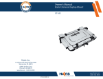
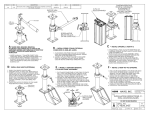
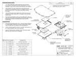
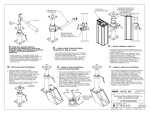
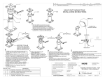
ChargeGuard® Auto Shut-off Timer
HOW IT WORKS
•
Havis ChargeGuard®
Auto Shut-off Timer
•
•
•
Protect Your Battery
+ Protect Your Peripherals =
PRODUCTIVITY PROTECTION
PLEASE READ ALL WARNINGS
AND FOLLOW ALL INSTRUCTIONS TO
ENSURE PROPER OPERATION
SPECIFICATIONS (Part # CG-X)
Model Number:
Operating Voltage (nominal):
Low Voltage Disconnect:
High Voltage Disconnect:
Stand-by Current:
Operating Current:
Operating Temperature:
Load Current Rating:
Minimum Time Delay:
Selectable Time Delay:
3 Year Limited Warranty
Made in USA
DOCUMENT PART NUMBER:
CG-0006-IS-E
CG-X
13.8V DC
11V DC
18V DC
5mA
80mA
-30˚C to 70˚C
30A
5 sec.
5 sec. to Infinity
•
•
Supplies power to two-way radio, computer
or other equipment when vehicle is started
Keeps peripherals on after the engine
is turned off
Turns off peripherals after a pre-set time or
if vehicle’s battery shows signs of fatigue
Prevents dead batteries by shutting off
peripherals before excessive discharge to
ensure there is enough battery left to start vehicle
*Applies to typical batteries in good condition
Protects peripherals from voltage surges
and under/over voltage situations
Voltage Diagnostic LED display indicates if
vehicle voltage is too low or too high
BENEFITS
•
•
•
•
•
•
•
•
Turns on peripherals when you want them on
Turns off peripherals when you NEED them off
Saves battery wear & tear, and extends battery life
Reduces maintenance & service calls
Installs easily with simple set up
Convenient override/test button for testing
and emergencies
Works with many applications in multiple modes
Established track record with over 250,000
units installed
FEATURES
•
•
•
•
•
•
•
•
Selectable Timeout Delay
30 Amp Load Current Rating
Selectable Switch Modes
Hi & Low Voltage Disconnect
Reverse Polarity Protection
Override/Test Button
Rugged, durable construction
Voltage Diagnostic LED
INSTALLATION NOTES
MOUNTING
• ChargeGuard® may be mounted in the cabin or trunk
of the vehicle. It should be wired through a fuse
directly to the battery.
WARNING
• Mode must be selected before battery power is connected.
• ChargeGuard® should not be mounted under the hood or in any area that gets wet. Doing so would void the
warranty and pose a safety risk.
! • Do not expose to direct water or steam. Power is
present in the unit at all times unless disconnected
from the battery.
! • The ChargeGuard® must be used with an inline fuse
(Littelfuse #ATO 30, Slo-Blo 30A, or equivalent) on
input power. Fuses on power output are recommended
but not required and should be sized appropriately for
peripheral.
NOTE
• Ground connection to negative battery connector
must be less than 1.0 OHM.
• ChargeGuard® Ground terminal is for ChargeGuard
Ground ONLY.
• Failure to fuse device properly or use outside of
temperature operating range could result in an unsafe
condition.
WIRING DIAGRAM
IGN Mode Only
(Optional)
Havis, Inc.
75 Jacksonville Road, Warminster, PA 18974
1-800-524-9900 • www.havis.com
U.S. Patents 4,950,913 & 5,272,386 & 5,563,452 & 7,211,907
Canadian Patents 2,013,888 & 2,560,825
EASY FOUR STEP SET UP
BEFORE BEGINNING: Configure vehicle and peripherals to your desired specifications before installing ChargeGuard®.
1. SET THE TIME: Choose a time setting at which the unit
will turn your devices off automatically. This delay begins
the instant the engine is turned off. Time selection is made
via dip switch setting. See chart below for available settings.
(Use UL recognized wiring material):
Minimum wire size between “BAT” terminal and Battery
should be 10 gauge regardless of the fuse size, and larger
for long runs over 15 feet.
a) Connect appropriate size wire based on load and wire
length from “OUT” terminal to Peripherals
b) Connect 18 gauge wire from “GND” terminal to Vehicle
Chassis (Ideal ground connection is made directly back
to negative battery terminal)
c) IGN MODE ONLY: Connect 18 gauge wire from
“IGN” terminal to on/off power source
NOTE: Use inline fuses in all wire runs and ensure
that all wires are completely captured and terminals
are fully tightened.
2. CHOOSE A MODE:
! WARNING: Mode must be selected before battery power is connected.
DC Mode: Charge Voltage, DC Rise:
Responds to the rise and fall of battery voltage only. When
the vehicle’s engine is running, the alternator produces a
charge voltage that is greater than the nominal battery
voltage. The ChargeGuard unit automatically senses this
voltage change to turn on/off the peripherals. To select
this option, set mode switch to “DC”.
AC Mode: Charge Voltage, AC Sensing:
Responds to the AC ripple voltage produced by the vehicle’s
alternator. When the vehicle’s engine is running, the
alternator produces a charge voltage that has an AC ripple
characteristic riding on the battery voltage. The ChargeGuard
unit automatically senses this AC ripple voltage to turn
on/off the peripherals. In older ChargeGuard products
(CG-12D, CG-MP, etc), this is the traditional “normal” mode
for which CHARGEGUARD® is famous. To select this option,
set mode switch to “AC”.
Ignition Mode: Switched, DC-DC:
Responds to a switched voltage input (min. 2/3 battery
voltage, max 19V). This mode uses a separate wire to monitor
the ignition position; the ChargeGuard unit is then controlled
by the vehicle’s ignition. For proper/expected operation, it is
necessary to choose a connection that is a true ignition source
(not accessory, crank, etc). It may be necessary to choose this
mode of operation if the vehicle has a weak electrical system,
degraded batteries, hybrid battery technology, and/or other
limitations prohibiting sensing modes. To select this option,
set mode switch to “IGN” and connect an 18AWG jumper
wire from the ignition terminal to the ignition source.
TECHNICAL NOTES
3. HOOK UP THE WIRES
4. TEST INSTALLATION:
Press Emergency Override/Test Button: Power will be applied
to the peripherals for a minimum of 15 minutes (if time delay
is set for greater then 15 minutes power will be applied for
a period equal to current setting). Power will be turned off
when the timer runs out or if the vehicle voltage drops too
low. This is a convenient means to turn equipment on and off.
• Low voltage – To prevent a low battery condition,
if the battery falls below 11 volts, the ChargeGuard®
Auto Shut-off Timer unit automatically turns equipment
off in 15 minutes. Below 10 volts, the ChargeGuard®
Auto Shut-off Timer turns equipment off in 5 minutes.
Programmed delay setting is restored when vehicle
voltage returns to normal.
• High voltage – To protect equipment from high
voltage conditions commonly caused by an erratic
voltage regulator or 24V jump start, the ChargeGuard®
Auto Shut-off Timer immediately turns equipment
off above 18 volts.
• Reverse polarity – The unit will not operate when
the voltage is reversed. Both the equipment and the
ChargeGuard® Auto Shut-off Timer are protected from
damage due to an improper installation or jump-start.
• Surge/Transient – To protect equipment from voltage
surges and spikes common in electrical systems, the
ChargeGuard® Auto Shut-off Timer has internal transient
suppression built in.
TERMINAL GUIDE (CG-X)
NOTE: As added protection, the override function is disabled
during high voltage conditions above 18 volts.
NOTE: Holding the override button in for 3 seconds will
turn the ChargeGuard® Auto Shut-off Timer off. If the
engine is still running, or an active signal is still present
at the “IGN” terminal this will temporarily disable the
unit until button is released.
DIAGNOSTIC LED REFERENCE GUIDE
•
•
•
•
•
LED Off
Solid Green
Blinking Green
4 Blink Red
2 Blink Red
(Relay De-energized)
(Relay Energized)
(Relay Energized, Timer Counting)
(High Voltage Condition, > 18V)
(Low Voltage Condition, < 11V)
BAT
Connect to
the Battery
OUT
Connect to
external
equipment
LED
IGN
Connect to
a switched
source
(IGN Mode only)
GND
Connect to
the Vehicle
Chassis