1
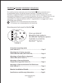
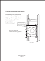
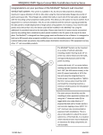
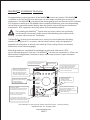
MiniRaQ
(TM*)
Installation Overview
(TM)
(TM)
Congratulations on your purchase of the MiniRaQ vertical rack system. The MiniRaQ
is available in 4U, 6U and 8U sizes based on size and usage restrictions for a variety of
applications. The MiniRaQ(TM) is designed from heavy gauge steel and finished to last a lifetime.
It is designed to hold up to 400 pounds when properly installed for your most demanding
needs such as extended runtime battery back up systems, low profile power distribution
transformers, POE equipment and many other rack mountable products.
(TM)
Warning
For installing the MiniRaQ System into any other surface not specifically
mentioned in this manual, please consult local building code requirements
to insure safe and secure installation.
The MiniRaQ(TM) System can be mounted on a variety of vertical substrates including
wooden framing studs 16” on center, solid or block concrete walls, and approved
plywood electrical panel or directly onto existing 2 Post racking. Please see detailed
instructions on the following pages.
Mounting hardware is provided for installing into solid wall studs and #12-24
screws for mounting on 2 Post rack. The MiniRaQ(TM) can even be mounted in a 2 Post rack
Back-to-Back configuration if clearances allow, which may increase U space utilization
in some instances.
Built in level allows easy installation
for single service personnel
Top access for data
or power cabling
The apparatus allows attachment
for 1U or 2U patch panel directly
inside the back-panel without
sacrificing any space in the mounting
surface of the side panels.
Lances are incorporated into the
(TM)
MiniRaQ to allow data and
power cable management for
input and output wiring using
either top or bottom egress,
as well as to facilitate service loops.
Earth Grounding Stud
integrated further
assisting quick and
convenient system install
Large rear panel access allows
pass though cable routing in
2 Post Back-to-Back
mounting applications
Back-plate of apparatus is designed with
3 mounting options:
“A” hole pattern (10) allows mounting
in standard 2 post open frame rack.
“B” Slots are centered at 16 inches
for #10 by 2” screws (10) into studs
or other solid wood surface.
“C” hole pattern (10) accommodates
toggle bolts for mounting on block wall
or NEC electrical panel grade plywood.
Ancillary equipment, both rack
and non-rack mountable, can be
attached to the side of the
back-panel by hanging or screwing
onto the back-panel.
B
A
C
FIGURE 1
All Trademarks are the property of their respective owners. *Patents pending.
BlackHawk Labs, LLC Copyright 2007
www.miniraq.com
PAGE 1
MiniRaQ
(TM)
Detailed Installation Instructions
(TM)
First confirm that the main back panel of the MiniRaQ will be mounted onto a
recommended surface and be sure proper hardware is available to proceed.
Hardware is supplied for both 2 Post rack (kit contains 10 #12-24 relay rack screws)
and wooden framing studs 16” on center (kit contains 10 #10 x 2” Stainless Steel screws).
If installing into concrete or approved plywood electrical panel be sure to have
appropriate 1/4” hexhead concrete screws**, lag bolt inserts* or toggle bolts* before
continuing with installation.
10 fasteners are recommended for full rated load
! ***10
fasteners are recommended for full rated load
Note
(TM)
Mounting main back panel for MiniRaQ
B
A
C
Close up detail of
Mounting hole patterns
for different hardware options
Available to install the
MiniRaQ(TM) System
FIGURE 2
2 Post Rack mounting option
(Hole Pattern A)......................................................................Page 3
Mounting into 16 inches on center
solid wood wall studs (Hole Pattern B)..............................Page 4
Mounting to Cinder Block or Approved
Hollow Wall (Hole Pattern C)...............................................Page 5
Mounting to Concrete Wall with
Compression Lags (Hole Pattern C)....................................Page 6
Mounting to Concrete Wall with TAPCON® bolts
(Hole Pattern C)......................................................................Page 6
Bracket Installation Details..........................................Page 7
Specifications and Warranty Information........................Page 8
www.miniraq.com
PAGE 2
2 Post Rack mounting option (Hole Pattern A)
Using supplied #12-24 screws align and
insert 1 screw. Do not fully tight screw but
engaged enough to hold up back panel.
Using integrated level, adjust panel and
add second screw to opposite post.
Add remaining 8 screws
and then tighten all.
Next go to bracket
Begin installing #12-24 Screws
installation details (pg 7).
at the top using the integrated
Secure both top and bottom of
2 Post Relay Rack before loading
MiniRaQ (TM)
Level to locate proper mounting
pattern. 10 screws recommended
for full payload rating of system.
Close up detail of
2-Post Mounting option
FIGURE 3
www.miniraq.com
PAGE 3
Close up detail of
16” Center to Center
Mounting option
Locate solid studs, 16 inches on
center before marking top two
locations for pilot holes.
Drill .156” at the top using
the integrated level to locate
proper mounting pattern.
Begin installing supplied
screws in pilot holes at the
top then drill and install
remaining screws in the
pattern. 10 screws
recommended for full
payload rating of system.
Mounting into 16 inches on center
solid wood wall studs (Hole Pattern B)
Place the MiniRaQ(TM) main back panel
against the wall in the preferred location.
Confirm location of stud centers and for
at least one TOP pilot hole. Drill pilot
hole using 5/32” bit (not supplied).
Place the first #10 wood screw through
top slot B and insert screw most of the way
into stud. Using integrated level, adjust
panel and drill remaining TOP Pilot hole
and insert screw most of the way into stud.
All remaining pilot holes can be drilled and
screws inserted into holes as above.
Tighten all screws.
Next go to bracket installation details (pg 7).
www.miniraq.com
PAGE 4
FIGURE 4
Mounting to Cinder Block or Approved Hollow Wall (Hole Pattern C)
Place the MiniRaQ(TM) main back panel against the wall in the preferred location.
Using integrated level, adjust panel to level thenmark a minimum of the two
top and two bottom ½ inch clearance holes (Hole C). Drill marked holes and apply
Togglers® or other associated inserts as required. Lift main back panel and hand
tighten bolts and fender washers (not supplied) most of the way into stud.
Tighten all screws.
Next go to bracket installation details (pg 7).
!
Note
!
Note
An approved hollow wall application is considered to be either of the following;
Cinder Block wall or NEC type 3/4” plywood electrical panel backing using
toggle bolts is safe for full rated load of MiniRaQ(TM) System.
In the event that this bracket is to be mounted on a block wall 1/4” x 3” toggle
bolts should be used to support it. It will be important that the hollow pocket
in the block is located so that the toggle can open properly to support the
weight. Toggle bolt clearance hole is 1/2” (bolts and washers not supplied;
available for purchase separately).
This Illustration shows recommended
mounting pattern for concrete screws
with fender washers
FIGURE 5
www.miniraq.com
PAGE 5
Mounting to Concrete Wall with Compression Lags (Hole Pattern C)
Place the MiniRaQ(TM) main back panel against the wall in the preferred location.
Refer to Figure 5 on Page 5 for correct mounting hole pattern.
Using integrated level, adjust panel and to level and mark a minimum of the
two top and two bottom ½ inch clearance holes (Hole C) Drill marked holes as
required and apply compression studs or other associated inserts as required.
Lift main back panel and hand tighten bolts and fender washers (not supplied)
most of the way into stud. Tighten all screws.
Next go to bracket installation details (pg 7).
Mounting to Concrete Wall with TAPCON® bolts
(Hole Pattern C)
Place the MiniRaQ(TM) main back panel against the wall in the preferred location.
Refer to Figure 5 on Page 5 for correct mounting hole pattern.
Using integrated level, adjust panel and to level and mark a minimum of the two top,
two bottom and two middle 1/2” clearance holes (Hole C) Drill 5/32” pilot holes
for 3/16” bolts, or 3/16” for 1/4” bolts pilot holes as required by manufacturer.
Apply TAPCON® or equivalent concrete double threaded screws. A minimum
2 1/4” length is recommended for full rated loading of MiniRaQ.
Lift main back panel and hand tighten bolts and washers (not supplied) most of
the way into wall. Tighten all screws.
Next go to bracket installation details (pg 7).
Caution: The MiniRaQ must be properly installed to a suitable surface and using
recommended hardware per instructions provided.
(TM)
Warning
www.miniraq.com
PAGE 6
(TM)
Bracket Installation Details for MiniRaQ
System
With the MiniRaQ(TM) main back panel mounted the left and right brackets can be
set in place and secured. The MiniRaQ(TM) main back panel accommodates all brackets
sizes available, 4U, 6U and 8U versions.
Proper orientation is required to secure brackets after engaging the tabs to allow
safety screw placement.
Right Bracket
Smooth surface
faces out
Left Bracket
Inside surface
(with tabs)
FIGURE 6
Bracket Arm
Security screw
located here
(1 each bracket)
Engage one bracket at a time confirming all tabs
are nested into cutouts on MiniRaQ(TM) main back
panel (1) and slide down to fully set bracket.
The clearance hole in the bracket (2)
should now align with a threaded hole
in the MiniRaQ(TM) main back panel.
Apply a #12-24 screw (supplied)
and tighten. Repeat with opposite
bracket.
1
2
FIGURE 7
www.miniraq.com
PAGE 7
(TM)
MiniRaQ
Specifications
Item Measurement
Height: 19.25 in (489 mm)
Width: 19.00 in (483 mm)
Depth:
4U version: 9.50 in (241 mm)
6U version: 13.00 in (330 mm)
8U version: 16.50 in (419 mm)
Net Weight:
4U version: 13.0 lb (5.9 kg)
6U version: 16.0 lb (7.3 kg)
8U version: 19.0 lb (8.6 kg)
Maximum Equipment Depth 38.00 in (965 mm)
Effective Rack Mounting Space:
4U version 4U + 2U Patch Panel + 1U each on Sides = 8U
6U version 4U + 2U Patch Panel + 1U each on Sides = 10U
8U version 4U + 2U Patch Panel + 1U each on Sides = 12U
Total Equipment Weight Capacity: 400.00 lb (181.44 kg)
Material: Heavy Duty 14AWG Steel
Finish: Chip Resistant Black Powder Coat
Shipping Dimensions: 20 X 20 X 3 inches All Versions
Shipping Weight:
4U version: 15.0 lb (6.8 kg)
6U version: 18.0 lb (8.2 kg)
8U version: 21.0 lb (9.5 kg)
Pallet Quantity: 48
Specifications are subject to change.
www.miniraq.com
PAGE 8
BlackHawk Labs, LLC Limited Factory Warranty
The limited warranty provided by BlackHawk Labs, LLC (BHL) in this Statement of Limited
Factory Warranty applies only to Products purchased for commercial or industrial use
in the ordinary course of your business.
Terms of Warranty
BHL warrants its products to be free from defects in materials and workmanship
for a period of five years (two years in Japan) from the date of purchase. Its obligation
under this warranty is limited to repairing or replacing, at its sole discretion, any such
defective products. This warranty does not apply to equipment that has been damaged
by accident, negligence, or misapplication or has been altered or modified in any way.
Repair or replacement of a defective product or part thereof does not extend the
original warranty period. Any parts furnished under this warranty may be new or
factory-reconditioned.
Non-transferable Warranty
This warranty applies only to the original purchaser who must have properly registered
the product. Product may be registered at www.bhpower.com/support.
Exclusions
BHL shall not be liable under the warranty if its testing and examination disclose that
the alleged defect in the product does not exist or was caused by end user’s or any
third person’s misuse, negligence or improper installation. Further BHL shall
not be liable under the warranty for unauthorized attempts to repair or modify
inappropriate on-site operating conditions, corrosive atmosphere, installation,
a change in location or operating use, exposure to the elements, Acts of God, fire,
theft, or installation contrary to BHL recommendations or specifications or in any
event if the BHL serial number has been altered, defaced, or removed, or any other
cause beyond the range of the intended use.
THERE ARE NO WARRANTIES, EXPRESS OR IMPLIED, BY OPERATION OF LAW OR
OTHERWISE, OF PRODUCTS SOLD, SERVICED OR FURNISHED UNDER THIS
AGREEMENT OR IN CONNECTION HEREWITH. BHL DISCLAIMS ALL IMPLIED
WARRANTIES OF MERCHANTABILITY, SATISFACTION AND FITNESS FOR A
PARTICULAR PURPOSE. BHL EXPRESS WARRANTIES WILL NOT BE ENLARGED,
DIMINISHED, OR AFFECTED BY AND NO OBLIGATION OR LIABILITY WILL ARISE
OUT OF, BHL RENDERING OF TECHNICAL OR OTHER ADVICE OR SERVICE IN
CONNECTION WITH THE PRODUCTS. THE FOREGOING WARRANTIES AND
REMEDIES ARE EXCLUSIVE AND IN LIEU OF ALL OTHER WARRANTIES AND
REMEDIES. THE WARRANTIES SET FORTH ABOVE CONSTITUTE BHL SOLE
LIABILITY AND PURCHASER’S EXCLUSIVE REMEDY FOR ANY BREACH OF SUCH
WARRANTIES. BHL WARRANTIES RUN ONLY TO PURCHASER AND ARE NOT
EXTENDED TO ANY THIRD PARTIES.
www.miniraq.com
PAGE 9
BHL WILL IN NO WAY BE LIABLE FOR ANY FORM OF INDIRECT, SPECIAL,
CONSEQUENTIAL OR PUNITIVE DAMAGES, ARISING OUT OF THE USE,
SERVICE OR INSTALLATION, OF THE PRODUCTS, WHETHER SUCH DAMAGES
ARISE IN CONTRACT OR TORT, IRRESPECTIVE OF FAULT, NEGLIGENCE OR STRICT
LIABILITY OR WHETHER BHL HAS BEEN ADVISED IN ADVANCE OF THE POSSIBLY
OF SUCH DAMAGES. SPECIFICALLY, BHL IS NOT LIABLE FOR ANY COSTS, SUCH AS
LOST PROFITS OR REVENUE, LOSS OF EQUIPMENT, LOSS OF USE OF EQUIPMENT,
LOSS OF SOFTWARE, LOSS OF DATA, COSTS OF SUBSTITUANTS, CLAIMS BY THIRD
PARTIES, OR OTHERWISE.
NO SALESMAN, EMPLOYEE OR AGENT OF BHL IS AUTHORIZED TO ADD TO OR VARY
THE TERMS OF THIS WARRANTY. WARRANTY TERMS MAY BE MODIFIED, IF AT ALL,
ONLY IN WRITING SIGNED BY AN BHL OFFICER AND LEGAL DEPARTMENT.
Warranty Claims
Customers with warranty claims issues may access the BHL worldwide customer support
network by visiting www.bhpower.com/support.
BHL Customer Support
Customer support for this or any other BHL product is available at no charge in any
of the following ways:
• Visit www.MiniRaQ.com website to access documents and to submit customer
support requests.
• www.bhpower.com (Corporate Headquarters)
Customer Support Line
877-427-2522 (toll free)
BHL headquarters USA
BlackHawk Labs, LLC
829 W. Stadium Lane, Unit B
Sacramento, CA 95834
Please recycle packaging materials
Entire contents copyright 2007 BlackHawk Labs, LLC. All rights reserved.
Reproduction in whole or in part without permission is prohibited. BHL, the BHL logo,
and MiniRaQ are trademarks of BlackHawk Labs, LLC. All other trademarks,
product names, and corporate names are the property of their respective owners
and are used for informational purposes only.
www.miniraq.com
PAGE 10