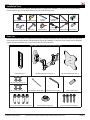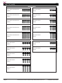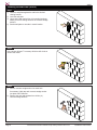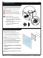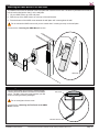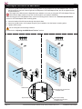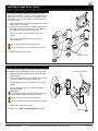
1
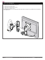
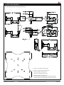
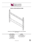
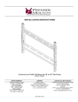
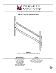
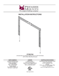
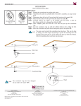
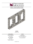
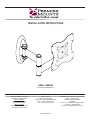
INSTALLATION INSTRUCTIONS
AM50 / AM50-B
Articulating Swingout Arm
NORTH AMERICA
EUROPE
AUSTRALIA AND OCEANIA
3130 East Miraloma Avenue
Anaheim, CA 92806 USA
USA and Canada
Phone: 1.800.368.9700
Fax: 1.800.832.4888
Other Locations
Phone: (001).714.632.7100
Fax: (001).714.632.1044
Swallow House,
Shilton Industrial Estate,
Shilton, Coventry, England CV79JY
Phone: +44 (0) 2476 614700
Fax: +44 (0) 2476 614710
Distributed by Amber Technology Limited
Unit B, 5 Skyline Place
Frenchs Forest NSW 2086
Australia
Phone: +61 2 9452 8600 Sydney Office
Toll Free: 1-800-368-9700
Email: [email protected]
9531-006-031-00
AM50
Contents
Weight Limit. ............................................................................................................................................................. 2
Warning Statements. ................................................................................................................................................ 2
Installation Tools. ...................................................................................................................................................... 3
Parts List................................................................................................................................................................... 3
Mounting Hardware. ................................................................................................................................................. 4
Features. .................................................................................................................................................................. 5
Installing the Wall Plate. ........................................................................................................................................... 6
Determining the Mounting Surface. ............................................................................................................. 6
Wood Stud Installation................................................................................................................................. 6
Concrete Installation. ................................................................................................................................... 7
Mounting Hardware. ................................................................................................................................................. 9
Selecting the Mounting Hardware. .............................................................................................................. 9
Universal Spacer Installation. .................................................................................................................... 10
UFP-280 Adapter Plate Installation. .......................................................................................................... 10
Attaching the AM50 Mount to the Wall Plate. ......................................................................................................... 11
Securing the AM50 Mount. ..................................................................................................................................... 11
Attaching the Flat Panel to the AM50 Mount. ......................................................................................................... 12
Adjusting the AM50 Mount Tension. ....................................................................................................................... 13
Adjusting the Swingout Arm Tension. ........................................................................................................ 13
Adjusting the Tilt/Pivot Tension. ................................................................................................................. 13
AM50 Cable Management. ..................................................................................................................................... 14
Technical Specifications. ........................................................................................................................................ 15
Warranty. ................................................................................................................................................................ 16
Weight Limit
Maximum Flat Panel Weight:
50 lbs.
THE WALL STRUCTURE MUST BE CAPABLE OF
SUPPORTING AT LEAST FIVE TIMES THE WEIGHT OF
THE FLAT PANEL. IF NOT, THE WALL STRUCTURE MUST
BE REINFORCED.
Warning Statements
PRIOR TO THE INSTALLATION OF THIS PRODUCT, THE INSTALLATION INSTRUCTIONS MUST BE READ AND
COMPLETELY UNDERSTOOD. KEEP THESE INSTALLATION INSTRUCTIONS IN AN EASILY ACCESSIBLE LOCATION
FOR FUTURE REFERENCE.
PROPER INSTALLATION PROCEDURE BY A QUALIFIED SERVICE TECHNICIAN MUST BE FOLLOWED, AS OUTLINED
IN THESE INSTALLATION INSTRUCTIONS. FAILURE TO DO SO COULD RESULT IN PROPERTY DAMAGE, SERIOUS
PERSONAL INJURY, OR EVEN DEATH.
SAFETY MEASURES MUST BE PRACTICED AT ALL TIMES DURING THE ASSEMBLY OF THIS PRODUCT. USE
PROPER SAFETY EQUIPMENT AND TOOLS FOR THE ASSEMBLY PROCEDURE TO PREVENT PERSONAL INJURY.
PREMIER MOUNTS DOES NOT WARRANT AGAINST DAMAGE CAUSED BY THE USE OF ANY PREMIER MOUNTS
PRODUCT FOR PURPOSES OTHER THAN THOSE FOR WHICH IT WAS DESIGNED OR DAMAGE CAUSED BY
UNAUTHORIZED ATTACHMENTS OR MODIFICATIONS, AND IS NOT RESPONSIBLE FOR ANY DAMAGES, CLAIMS,
DEMANDS, SUITS, ACTIONS OR CAUSES OF ACTION OF WHATEVER KIND RESULTING FROM, ARISING OUT OF OR
IN ANY MANNER RELATING TO ANY SUCH USE, ATTACHMENTS OR MODIFICATIONS.
At least two qualified people should perform the assembly procedure. Personal injury and/or property damage can result
from dropping or mishandling the flat panel.
If mounting to wall studs or ceiling studs, make sure that the mounting screws are anchored into the center of the wall studs
or ceiling studs. Use of an edge-to-edge stud finder is recommended.
It is recommended that a maximum of ⅝″ plaster board be used when mounting to wooden studs.
Be aware of the mounting environment. If drilling and/or cutting into the mounting surface, always make sure that there
are no electrical wires in wall. Cutting or drilling into an electrical line may cause serious personal injury.
Make sure there are no water or natural gas lines inside the wall where the mount is to be located. Cutting or drilling into a
water or gas line may cause severe property damage or personal injury.
This product is intended for indoor use only. Use of this product outdoors could lead to product failure and/or serious
personal injury.
Do not install near sources of high heat. Do not install on a structure that is prone to vibration, movement or chance of
impact.
Contact Premier Mounts with any questions:
(800) 368-9700
[email protected]
Page 2
Visit the Premier Mounts website at http://www.premiermounts.com
Installation Instructions
AM50
Installation Tools
The following tools may be required, dependent upon your particular installation. These tools are not provided by
Premier Mounts, but you can purchase them at your local hardware store.
Electronic Stud Finder Hand Held Drill
Protective Eyewear
Hammer**
** Optional tools for concrete installations.
⅛˝ Wood
Drill Bit
Tape Measure
/16˝ Masonry
5
Drill Bit**
Phillips Tip
Screwdriver
Pencil
Level
Socket Wrench M10 Socket**
Parts List
Your Premier Mounts product is shipped with all proper installation hardware and components. Make sure that none
of these parts are missing and/or damaged before beginning installation. If there are parts missing and/or damaged,
please stop the installation and contact Premier Mounts (800) 368-9700.
AM50 / AM50-B Articulating Swingout Arm Components
Wall Plate (Qty 1)
Articulating Swingout Arm (Qty 1)
UFP-280 Adapter Plate (Qty 1)
M4 Flat Washers (Qty 4)
M5 Flat Washers (Qty 4)
Thread Depth Indicator (Qty 1)
/16″ Concrete Wedge Anchors (Qty 4)
5
Installation Instructions
M3 Allen Wrench (Qty 1)
Universal Spacers (Qty 30)
14mm Socket (Qty 1)
#14 x 2″ Wood Screws (Qty 4)
Visit the Premier Mounts website at http://www.premiermounts.com
Page 3
AM50
Parts List (cont’d)
Mounting Hardware
M4 x 10mm Flat Head Screw
(Qty 6)
M5 x 10mm Screw
(Qty 4)
M4 x 16mm Flat Head Screw
(Qty 6)
M5 x 16mm Screw
(Qty 4)
M4 x 20mm Flat Head Screw
(Qty 6)
M5 x 20mm Screw
(Qty 4)
M4 x 30mm Flat Head Screw
(Qty 6)
M5 x 30mm Screw
(Qty 4)
M4 x 45mm Flat Head Screw
(Qty 6)
M5 x 45mm Screw
(Qty 4)
M6 x 10mm Screw
(Qty 4)
M4 x 5mm Screw
(Qty 4)
M6 x 16mm Screw
(Qty 4)
M4 x 10mm Screw
(Qty 4)
M6 x 20mm Screw
(Qty 4)
M6 x 30mm Screw
(Qty 4)
M6 x 45mm Screw
(Qty 4)
Page 4
Visit the Premier Mounts website at http://www.premiermounts.com
Installation Instructions
AM50
Features
Radial Glide Technology™
180° swing, 360° rotation and 15°
of tilt allows for superior viewing of
your flat panel.
Stylish Design
Sleek and unobtrusive, yet
supremely sturdy.
Universal Spacers
Premier Mount’s uniquely
designed spacers that fit multiple
screw sizes, and work with either
the AM50 mount or the UFP-280
Adapter Plate.
Adjustable Tension
Your flat panel stays at the angle
you choose regardless of size or
weight.
Cable Management
Keeps cables from being pinched
and reduces unsightly cable
clutter.
Installation Instructions
Versatile Mounting Points
The AM50 mount, in concert
with the UFP-280 adapter plate,
provides mounting points for
VESA 75mm x 75mm, 100mm
x 100mm, 200mm x 100mm,
and 200mm x 200mm mounting
configurations.
Visit the Premier Mounts website at http://www.premiermounts.com
Page 5
AM50
Installing the Wall Plate
Determining the Mounting Surface
If you will be installing your AM50 mount to wood studs, proceed to the “Wood Stud Installation” section.
If you will be installing your AM50 mount to a concrete wall, proceed to the “Concrete Installation” section.
Wo
od
Stu
d
Co
n
cre
te
Wood Stud Installation
Step 1
You must secure the wall plate to the wall stud with
all four (4) #14 x 2″ wood screws.
X
1) Use a stud finder to determine the exact center of wall
studs in the vicinity of the wall plate.
2) Use a pencil to mark the exact center of the wall stud
where you will be installing your AM50 mount.
Step 2
1) Place the wall plate against the wall in the desired
viewing location.
2) Adjust the wall plate to align the mounting points in
the wall plate with the center of the wall stud.
3) Level the wall plate.
4) Use a pencil to mark all four (4) mount locations along
the center of the wall stud.
Page 6
X
Visit the Premier Mounts website at http://www.premiermounts.com
Installation Instructions
AM50
Installing the Wall Plate (cont’d)
Step 3
Drill four (4) holes in the center of each of the marks
using a power drill and a ⅛˝ drill bit.
Only use a ⅛˝ drill bit when drilling the holes.
X
Step 4
1) Place the wall plate against the wall and align it with
the holes.
2) Insert one (1) #14 x 2″ wood screw into each of
the mounting holes and tighten using a Phillips
screwdriver.
X
Do not overtighten the wood screws.
Proceed to the “Mounting Hardware” section.
Concrete Installation
The supplied 5/16″ concrete wedge anchors must be
used for concrete installation.
You will need a 5/16″ masonry drill bit, which is
available at your closest hardware store.
Concrete Wedge Anchors
Example of 5/16″ Masonry Drill Bit (Not Included)
Installation Instructions
Visit the Premier Mounts website at http://www.premiermounts.com
Page 7
AM50
Installing the Wall Plate (cont’d)
Step 1
1) Place the wall plate against the wall in the desired
viewing location.
2) Level the wall plate.
3) Use a pencil and mark all four (4) mounting locations
where you will be drilling holes for the concrete wedge
anchors.
4) Set the wall plate to one side in a safe location.
Step 2
Use a power drill and 5/16″ masonry drill bit to drill a hole at
each of the marks.
Step 3
1) Insert a concrete wedge anchor into each hole.
If necessary, lightly tap each concrete wedge anchor
into place with a hammer.
2) Remove the nuts and washers from all four (4)
concrete wedge anchors.
Page 8
Visit the Premier Mounts website at http://www.premiermounts.com
Installation Instructions
AM50
Installing the Wall Plate (cont’d)
Step 4
1) Place the wall plate against the wall over the
threaded shafts of the concrete wedge anchors.
2) Attach the nuts and washers to each of the concrete
wedge anchors and tighten using a socket wrench
and an M10 socket.
Do not overtighten the wedge anchor nuts.
Proceed to the “Mounting Hardware” section.
Mounting Hardware
Selecting the Mounting Hardware
1) Insert the Thread Depth Indicator into the thread
inserts found on the bottom or top of the flat panel.
2) Use a pencil to mark the depth of the thread insert on
the Thread Depth Indicator, as shown in Figure 1.
3) Insert the Thread Depth Indicator into the remaining
thread inserts to compare and verify their depth.
4) Locate the correct diameter screw for the thread
insert.
If the screw you selected is longer than the mark on
the Thread Depth Indicator, as shown in Figure 2 and
Figure 3, do not use this screw. The screw length
must not bypass the mark.
5) Test the diameter for each of the screws provided in
the hardware pack.
The correct diameter screws should thread easily into
the mounting point and not pull out when tension is
applied.
Does your flat panel have:
●
●
●
●
Recessed mounting points?
Uneven mounting points?
A curved back?
Any obstruction near the mount point?
If Yes, you must install Universal Spacers. Proceed to
the “Universal Spacer Installation” section.
If No, skip to the “UFP-280 Adapter Plate Installation”
section.
Installation Instructions
Visit the Premier Mounts website at http://www.premiermounts.com
Page 9
AM50
Mounting Hardware (cont’d)
Universal Spacer Installation
Premier Mounts’ Universal Spacers allow you to attach
the mounting bracket to flat panels which have recessed
or uneven mounting points. Each Universal Spacer adds
¼˝ to the distance between the Adapter Plate and your
flat panel.
The Universal Spacers must be stacked and
oriented as shown.
The Universal Spacers must only be installed
between the Adapter Plate and your flat panel.
The Universal Spacers will fit M4, M5, M6 and M8 screw
sizes.
Does your flat panel have:
●
●
75mm x 75mm VESA mounting points or
100mm x 100mm VESA mounting points?
Proceed to the “Attaching the AM50 Mount to
the Wall Plate” section.
100mm x 200mm mounting points or 200mm x
200mm mounting points?
Proceed to the “UFP-280 Adapter Plate
Installation” section.
UFP-280 Adapter Plate Installation
The UFP-280 LCD Mount Adapter is used to attach flat
panels with 200mm X 100mm and 200mm x 200mm
mount point patterns to the AM50 mount.
1) Determine which mounting points will be used.
Refer to the “Technical Specifications” section for
UFP-280 Adapter Plate mount point patterns.
2) Place your monitor face-down on a soft and flat
surface.
3) Secure the UFP-280 Adapter Plate to the back of the
monitor using the following hardware:
If you are using the 100mm X 200mm mounting points,
you must use the M4 x 10mm Flat Head screws to
secure the UFP-280 Adapter Plate to the flat panel.
•
• If you are using the 200mm x 200mm mounting
points...
...and you selected M4 screws from the “Selecting the
Mounting Hardware” section, you must also use M4
flat washers.
...and you selected M5 screws from the “Selecting the
Mounting Hardware” section, you must also use M5
flat washers.
Proceed to the “Attaching the AM50 Mount to the Wall
Plate” section.
Page 10
Visit the Premier Mounts website at http://www.premiermounts.com
Installation Instructions
AM50
Attaching the AM50 Mount to the Wall Plate
Your AM50 mount must be attached to the back plate that is secured to the wall. The back of your AM50 mount has a
built-in bracket designed to “hang” on the wall plate.
1) Lift your AM50 mount up to the wall plate.
2) Slide the top of the AM50 mount on to the top of the wall bracket.
3) Pivot the bottom of the AM50 mount towards the wall plate until it rests against the wall.
Do not release the AM50 mount until you are certain that it is resting securely on the wall plate.
Proceed to the “Securing the AM50 Mount” section.
AM50 Mount
X
Wall Plate
Securing the AM50 Mount
Use the supplied M3 Allen wrench to tighten the M6
x 35mm set screw located in the bottom of the AM50
mount. The M6 x 35mm set screw prevents your flat
panel from being accidently dislodged.
Set Screw
Do not overtighten the set screw.
Proceed to the “Attaching the Flat Panel to the AM50
Mount” section.
M3 Allen Wrench
Installation Instructions
Visit the Premier Mounts website at http://www.premiermounts.com
Page 11
AM50
Attaching the Flat Panel to the AM50 Mount
1) Insert two (2) M4 screws into the top two mounting points of your flat panel or UFP-280 Adapter Plate. Thread
the M4 screws to one-half of their length into the flat panel or UFP-280 Adapter Plate, but do not tighten the M4
screws at this time.
The length of the M4 screws are dependent upon whether or not you are using the UFP-280 Adapter Plate, as
shown below. Make certain you use the correct length for your specific installation.
If you are using the UFP-280 Adapter Plate, use the B mounting points. Refer to the “Technical Specifications”
section for UFP-280 Adapter Plate mounting points.
2) Insert the heads of the M4 screws through the keyhole slots.
3) Insert two (2) M4 screws, of the proper length for your installation, into the bottom mounting points.
4) Tighten all M4 screws.
Do not overtighten the mounting hardware.
Proceed to the “Adjusting the AM50 Mount Tension” section.
Flat Panel without UFP-280 Adapter Plate
Flat Panel with UFP-280 Adapter Plate
M4 x 10mm Screw
M4 x 5mm Screw
AM50 Mount
Keyhole Slot
Page 12
Thread Insert in Flat Panel
or Adapter Plate
M4 Screw Partially
Threaded Into Flat Panel
or Adapter Plate
Visit the Premier Mounts website at http://www.premiermounts.com
Installation Instructions
AM50
Adjusting the AM50 Mount Tension
Adjusting the Swingout Arm Tension
Your AM50 Articulating Swingout Arm ships from the
factory pre-tensioned. However, you can make fine-tune
adjustments to how much pressure is required to move
each section of the swingout arm by adjusting the three
joint tension nuts.
1) Remove the plastic joint caps from the bottom of each
of the swingout arm joints.
2) Use a socket wrench and the supplied 14mm socket
to loosen or tighten the joint tension nut located on
the underside of each swingout arm joint.
Turn the joint tension nut clockwise to increase
tension.
Turn the joint tension nut counter-clockwise to
decrease tension.
Do not overtighten the joint tension nuts.
Do not completely remove the joint tension nuts.
3) Replace the plastic joint caps.
Joint Tension Nut
Adjusting the Tilt/Pivot Tension
You can adjust the tension of the Radial Glide™ flat panel
attachment head by adjusting the tilt/pivot tension nut.
Radial Glide™ Head
1) Remove the plastic tilt/pivot cap on the back of the
tilt/pivot head.
2) Use a socket wrench and the supplied 14mm socket
to loosen or tighten the tilt/pivot tension nut.
Turn the tilt/pivot tension nut clockwise to increase
tension.
Turn the tilt/pivot tension nut counter-clockwise to
decrease tension.
Caution!
Loosening the tilt/pivot tension nut too much may
cause the flat panel to suddenly tilt forward.
Do not overtighten the tilt/pivot tension nut.
Do not completely remove the tilt/pivot tension nut.
3) Replace the plastic tilt/pivot cap.
Proceed to the “AM50 Cable Management” section.
Installation Instructions
Visit the Premier Mounts website at http://www.premiermounts.com
Tension Nut
Page 13
AM50
AM50 Cable Management
Your AM50 features built-in cable management.
1) Remove the four plastic covers.
2) Route power or signal cables as shown.
3) Replace the four plastic covers.
The V-shape in the plastic covers allows power and signal cables to emerge from your AM50 while still maintaining
a clean appearance.
Page 14
Visit the Premier Mounts website at http://www.premiermounts.com
Installation Instructions
AM50
Technical Specifications
All measurements are in inches [millimeters].
A: 75mm x 75mm VESA mounting points.
B: 100mm x 100mm VESA mounting points.
C: 100mm x 200mm mounting points.
(M4 x 10mm Flat Head screws only)
D: 200mm x 200mm mounting points.
(If M4 screws are used, M4 washers must be used as well)
(If M5 screws are used, M5 washers must be used as well)
Installation Instructions
Visit the Premier Mounts website at http://www.premiermounts.com
Page 15
AM50
Warranty
PREMIER MOUNTS
LIMITED LIFETIME WARRANTY
What and Who is Covered by this Limited Warranty and for How Long
Premier Mounts warrants this product to be free from defects in material and workmanship for the lifetime of the original
owner of this product. The limited warranty is valid only for the original purchaser of the product.
What Premier Mounts Will Do
At the sole option of Premier Mounts, Premier Mounts will repair or replace any product or product part that is defective.
If Premier Mounts chooses to replace a defective product or part, a replacement product or part will be shipped to you
at no charge, but you must pay any labor costs.
What is Not Covered; Limitations
PREMIER MOUNTS DISCLAIMS ANY LIABILITY FOR DAMAGE TO MOUNTS, ADAPTERS, DISPLAYS,
PROJECTORS, OTHER PROPERTY, OR PERSONAL INJURY RESULTING, IN WHOLE OR IN PART, FROM
IMPROPER INSTALLATION, MODIFICATION, USE OR MISUSE OF ITS PRODUCTS.
PREMIER MOUNTS DISCLAIMS ALL OTHER WARRANTIES, EXPRESS OR IMPLIED, INCLUDING WARRANTIES
OF MERCHANTABILITY AND FITNESS FOR A PARTICULAR PURPOSE. PREMIER MOUNTS IS NOT
RESPONSIBLE FOR INCIDENTAL OR CONSEQUENTIAL DAMAGES, INCLUDING BUT NOT LIMITED TO,
INABILITY TO USE ITS PRODUCTS OR LABOR COSTS FOR REMOVING AND REPLACING DEFECTIVE
PRODUCTS OR PARTS. SOME STATES DO NOT ALLOW THE EXCLUSION OR LIMITATION OF INCIDENTAL OR
CONSEQUENTIAL DAMAGES, SO THE ABOVE LIMITATION OR EXCLUSION MAY NOT APPLY TO YOU.
What Customers Must Do for Limited Warranty Service
If you discover a problem that you think may be covered by the warranty you MUST REPORT it in writing to the address
below within thirty (30) days. Proof of purchase (an original sales receipt) from the original consumer purchaser must
accompany all warranty claims. Warranty claims must also include a description of the problem, the purchaser’s name,
address, and telephone number. General inquiries can be addressed to Premier Mounts Customer Service at 1-800368-9700. Warranty claims will not be accepted over the phone or by fax.
Premier Mounts
Attn: Warranty Claim
3130 East Miraloma Ave.
Anaheim, CA 92806
How State Law Applies
THIS WARRANTY GIVES YOU SPECIFIC LEGAL RIGHTS, AND YOU MAY ALSO HAVE OTHER RIGHTS WHICH
VARY FROM STATE TO STATE.
Disclaimer
Premier Mounts intends to make this manual accurate and complete. However, Premier Mounts makes no claim that
the information contained herein covers all details, conditions or variations, nor does it provide for every possible
contingency in connection with the installation or use of this product. The information contained in this document
is subject to change without notice or obligation of any kind. Premier Mounts makes no representation of warranty,
expressed or implied, regarding the information contained herein. Premier Mounts assumes no responsibility for
accuracy, completeness or sufficiency of the information contained in this document.
©Premier Mounts 2010
Page 16
Visit the Premier Mounts website at http://www.premiermounts.com
Installation Instructions