1
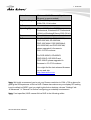
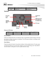
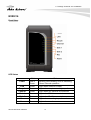
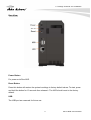
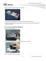
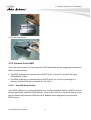
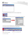
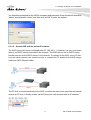
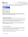
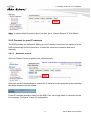
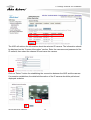
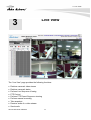
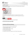
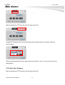
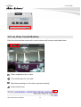
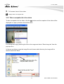
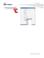
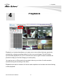
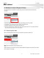
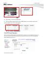
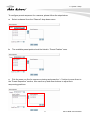
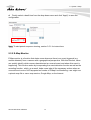
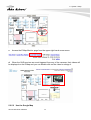
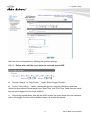
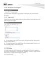
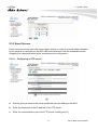
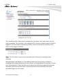
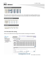
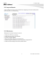
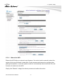
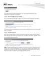
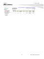
AirLive NVR Serials
Network Video Recorder
User’s Manual
Copyright & Disclaimer
Copyright & Disclaimer
No part of this publication may be reproduced in any form or by any means, whether
electronic, mechanical, photocopying, or recording without the written consent of OvisLink
Corp.
OvisLink Corp. has made the best effort to ensure the accuracy of the information in this
user’s guide. However, we are not liable for the inaccuracies or errors in this guide.
Please use with caution. All information is subject to change without notice
All Trademarks are properties of their respective holders.
i
AirLive NVR User’s Manual
Copyright & Disclaimer
FCC Interference Statement
The NVR has been tested and found to comply with the limits for a Class B digital device
pursuant to Part 15 of the FCC Rules. These limits are designed to provide reasonable
protection against radio interference in a commercial environment. This equipment can
generate, use and radiate radio frequency energy and, if not installed and used in
accordance with the instructions in this manual, may cause harmful interference to radio
communications. Operation of this equipment in a residential area is likely to cause
interference, in which case the user, at his own expense, will be required to take whatever
measures are necessary to correct the interference.
AirLive NVR User’s Manual
ii
Table of Contents
Table of Contents
1. Overview ................................................................................................ 1
1.1 Introduction........................................................................................ 1
1.2 Features ............................................................................................ 4
1.3 Product Specification ......................................................................... 4
1.4 System Requirement ......................................................................... 5
2. Package Contents and Installation....................................................... 7
2.1 Package Content ............................................................................... 7
2.2 Hardware Overview ........................................................................... 8
2.3 Hardware Installation ....................................................................... 12
2.4 Start to Use the NVR ....................................................................... 18
3. Live View .............................................................................................. 22
3.1 Retrieve camera’s video stream....................................................... 23
3.2 Retrieve camera’s status ................................................................. 23
3.3 Perform Sequence Viewing ............................................................. 24
3.4 PTZ Control ..................................................................................... 25
3.5 Perform PTZ Preset Viewing............................................................ 25
3.6 Live Video Control Buttons .............................................................. 28
3.7 Change Web UI Display Language.................................................. 30
4. Playback............................................................................................... 32
4.1 Methods to Search Playback Videos................................................ 33
4.2 Export Playback Videos to AVI Files ................................................ 39
4.3 Play Export Playback Videos with NVR Media Player...................... 41
5. System Setup....................................................................................... 43
5.1 System Configurations..................................................................... 43
5.2 Channel Configurations ................................................................... 49
5.3 Event Configurations ....................................................................... 62
5.4 Recording Configurations ................................................................ 69
i
AirLive NVR User’s Manual
Table of Contents
5.5 System Options ............................................................................... 74
6. Appendix .............................................................................................. 80
A. HDD compatibility list ........................................................................ 80
AirLive NVR User’s Manual
ii
1. Overview
1
1. Overview
1.1 Introduction
AirLive NVR serial products are Network Video Recorder for home, retailer store and small
office applications; with AirLive NVR, you don’t have to prepare another PC for your daily
monitoring job. AirLive NVR can connect up to 4/8/16 IP-based cameras for high quality,
real-time video viewing, recording and playback. The IP Camera PNP function provides an
easy way to setup your surveillance system; by a few clicking on the build-in web pages of
AirLive NVR, users can search, configure and receive the video clips from his IP-based
cameras without any suffering. AirLive NVR supports two high-speed SATA II hard drivers
and raises its capacity up to 2TB; with the H.264 video compression format, it could keep
video clips for more than 200 hours (4Mb bitrates per channel).
Recording Video Clip without You Computer
AirLive NVR utilizes the embedded Linux technology, and so eliminates users from
experiencing the annoying hardware compatibility issues from a PC/Software based
recording system. Furthermore, the AirLive NVR provides a build-in, web-based GUI that
gives users an easy-to-access, easy-to-watch, easy-to-manage way for working with.
1
AirLive NVR User’s Manual
1. Overview
Fully Control on Your IP-based Cameras
AirLive NVR supports almost all AirCam IP cameras, the most stable and cost-efficient IP
cameras in the market place nowadays. It also supports PTZ Control, Preset Point Patrol,
Motion Detection Recording, e-Mail Alert and FTP Upload, which won’t let you miss any
critical moment that you concerned. With AirCam IP camera, AirLive NVR will be your most
reliable guard for securing your family and property.
E-Map function for Live Street Monitor
User might utilize the Google Map or upload his floor plan to the AirLive NVR. Just
few steps of drag-and-drop operation, user could use the camera icons for denoting the
location of the IP cameras. In case of some IP camera triggered by an event, a live view
window will popup right beside the corresponding camera icon for alerting the user that
there is something unusual in front of that camera. With this function, user can quickly make
a response to the intruder or accident.
AirLive NVR User’s Manual
2
1. Overview
Multiple Video Compression Format Support
AirLive NVR supports H.264, MPEG-4 and MJPEG video compression format. H.264 is a
high performing video compression standard that boasts a much higher compression ratio
than others, drastically reducing file sizes and conserving valuable network bandwidth and
storage space. With up to 90% reduction in file size, a 1 MB image can be drastically
reduced to as low as 10KB using H.264.
Smart Phone Live Browsing
The mobile view function let you browse your AirLive NVR via your smart phone. Through
the 3G, 3.5G or even 4G mobile networks, user might receive the image from his AirLive
NVR when on his business trap, vacation, or just leaving for shopping.
3
AirLive NVR User’s Manual
1. Overview
1.2 Features
Support up to 4/8/16 IP Base Camera
Recording Video Clip without You Computer
Support Easy Installation, IP Camera Plug and Play
Support 2X SATAII Hard Driver, High-Capacity Storage up to 2TB
Support Multi-Channel Recording, Playback, Motion Detection
E-Map function for Live Street Monitor
Support Pan and Tile Function
Support 10/100/1000 Giga Lan port
1.3 Product Specification
Model
NVR
CPU
Marvell 500Mhz
Memory
128 MB DDR Ram
HDD
SATA II x 2
Network
Gigabit, half duplex/full duplex auto-negotiation
Camera Support
Support IP-based Camera (AirLive, Axis, Sony,
Panasonic, Vivotek )
Video Compression
H.264, MPEG-4, MJPEG
Resolution
Up to 1280 x 1024
Max. FPS
Support 30FPS for Each Channel
Audio
Two-way audio
Live View
Split Screen/Full Screen
PTZ Control
Sequence Mode
Snapshot
E-Map
Smart Phone Live Browsing
AirLive NVR User’s Manual
4
1. Overview
Playback
Split Screen
Full Screen
Playback Control
(Play/Pause/Stop/Forward/Reverse/Speed
Adjust/Step by Step)
AVI Export
Recording
More than 200 Hours (with 2 x 1TB HDD)
Manual/Continuous/Schedule/Event Recording
Protocols
HTTP
SMTP
DHCP
ARP
NTP
DNS
UPnP
FTP
RTP
RTSP
Event
System Events:
System Start
Shutdown
System Settings modified
Camera Settings Modified
Start Recycle,
Camera Events
Motion Detection
Sensor Detection
1.4 System Requirement
The following are minimum system requirements for you to operate AirLive NVR
Hardware
CPU
Minimum Intel® Pentium® 4 2.4 GHz or
higher (Dual Core Processor is
recommended)
RAM
Minimum 1 GB of RAM, 2GB or above is
recommended
5
AirLive NVR User’s Manual
1. Overview
Network
Minimum 10/100 Ethernet (Gigabit
Ethernet is recommended)
Graphics Adapter
AGP or PCI-Express, minimum
1024×768, 16 bit colors
Software
Operating System
Microsoft® Windows® 2000
Professional, Windows® XP Professional
(32 bit) or Windows® Server 2003 (32 bit)
Browser
Microsoft Internet Explorer 6 or above
IP Camera
For WL-2000CAM, POE-100CAM,
POE-200CAM, OD-300CAM,
POE-100CAMv2, POE-200CAMv2,
WL-2600CAM, and POE-260CAM,
please upgrade it’s firmware to
LM.1.6.16.05 or above.
For POE-200HD, OD-600HD,
POE-250HD, OD-325HD and
POE-100HD, please upgrade it’s
firmware to 5.0.3713 or above.
You might find the last released firmware
on our web site:
http://www.airlive.com
Note: We highly recommend you to set your Screen resolution to 1024 x 768 or above for
getting the full experience of AirLive NVR. Please also make sure your display DPI setting
is set to default at 96DPI, and you might right-click on desktop, choose “Settings” tab
“Advanced” “General” for further configuring your desktop environment.
Note: If not specified, NVR means AirLive NVR in the following article.
AirLive NVR User’s Manual
6
2. Package Contents and Installation
2. Package Contents
and Installation
2
2.1 Package Content
User can find the following items in the package as below:
Item
Descriptions
1. AirLive NVR: the main unit
of AirLive NVR
NVR8/16
or
NVR4
2. Power adapter: the
dedicate power adapter for
AirLive NVR
3. Ethernet cable: for connect
the AirLive NVR to your switch.
4. Screw Packet: for fixing the
HDD inside the AirLive NVR
7
AirLive NVR User’s Manual
2. Package Contents and Installation
5. Bundle CD: includes the
Search Utility/User’s
Manual/QIG
6. Quick Installation
Guide(QIG): printed Quick
Installation Guide
2.2 Hardware Overview
NVR4
Front View:
Power On/Off
Switch
LED
Indicator
(System
Status and
Data
Access)
Manual Recording
USB Upstream Port
(Reserve for future
use)
LED Status
Solid
AirLive NVR User’s Manual
System Status
(Green)
System Ready
8
Data Access
(Amber)
Recording
2. Package Contents and Installation
Blinking
Off
System Shutting Down
System Off
Manual Recording
Recording Off
Rare View:
Security
Lock
Slot
Ventilation
Fan
USB Upstream
Port (Reserve
for future use)
Gigabit
Ethernet
Port
DC Input
Reset
Button
Restart
Button
Ethernet LED Status
LED Status
Speed
Green
10 Mbps
Yellow
1000 Mbps
Green & Yellow
100 Mbps
Restart Button
Press and release the button for hardware restart. The OS LED should should go off during
the restart to indicate the system is restarting. The LED should indicate in solid green once
the system becomes ready.
Reset Button
Press this button will restore the system’s settings to factory default values. To start, press
and hold the button for 5 seconds then release it once the OS LED goes off. The OS LED
should indicate in solid green once the system becomes ready.
9
AirLive NVR User’s Manual
2. Package Contents and Installation
NVR8/16
Front View:
LED Status
Power
LAN
Recycle
Channel
Disk 1
Disk 2
Rec
Alarm
AirLive NVR User’s Manual
Color
Red or
Green
Green
Green
Green
Green
Green
Green
Green
Status
Blinking red indicating NVR is initializing,
Green: Normal operation
Light when network is ready
Light when recycle recording is performed
Light when any camera is connected
Light when Disk1 is mounted
Light when Disk2 is mounted
Light when recording is performed
Light when an alarm occurs
10
2. Package Contents and Installation
Rare View:
Power Button
For power on/off the NVR.
Reset Button
Press this button will restore the system’s settings to factory default values. To start, press
and hold the button for 10 seconds then release it. The NVR should reset to the factory
default.
USB
The USB port are reserved for future use.
11
AirLive NVR User’s Manual
2. Package Contents and Installation
2.3 Hardware Installation
2.3.1 Install the Hard Disk (NVR4)
Remove the four screws from the bottom of the case.
Push the inner enclosure out, and remove the outer chassis.
Install the first hard drive by placing it in the enclosure and connecting the SATA plus
power cables.
AirLive NVR User’s Manual
12
2. Package Contents and Installation
Mount the drive with two screws on each side.
Attach the thermal probe with the tape provided to the first hard drive.
Install the second hard drive by placing it in the enclosure and connecting the SATA
plus power cables.
2.3.2 Install the Hard Disk (NVR8/16)
Remove the back panel.
Insert the disks and push it until the SATA connector is closed.
Scroll the screws for fixing the disks.
13
AirLive NVR User’s Manual
2. Package Contents and Installation
Put the back panel.
2.3.3 Connect to the NVR
There are various ways you can connect to NVR and below are the suggested methods for
different network setup:
The NVR is placed in a network with a DHCP server: Connect to the NVR by using
“NVR Search” Utility
The NVR is placed in a network without DHCP server (or you are connecting to it
directly): Access NVR with its default IP: 192.168.1.1
2.3.2.1 Use NVR Search Utility
If the NVR is placed in a corporate network or a local area network where a DHCP server is
already presented, install the “NVR Search” utility on the CD from a computer that is on the
same network and locate the NVR with its IP address that is assigned by the top-level
DHCP server.
AirLive NVR User’s Manual
14
2. Package Contents and Installation
To begin, install the “NVR Search” utility from the CD and proceed with the installation:
Once the installation is complete, you might start the search tool by clicking
“Start””Program File””AirLive””NVR Search””NVR Search”.
The search should start automatically and its status should be displayed:
The NVR should be located and its IP address should be displayed: Double-click on it and
the program should automatically access the NVR’s web page from your default browser
15
AirLive NVR User’s Manual
2. Package Contents and Installation
You may change NVR’s IP address by click on the button highlighted below.
You will be prompted for the NVR’s login information before proceeding to change device’s
IP address.
You may click on the button highlighted below to perform search again. Or double-click on
any of the search results to access NVR’s web ad- ministration page
Perform NVR Searching again.
AirLive NVR User’s Manual
Double click for accessing the NVR
16
2. Package Contents and Installation
You should be prompted for the NVR’s username and password. Enter its default username
“admin” and password “airlive” and then click on”OK” to enter the system
2.3.2.2 Access NVR with its default IP address
The NVR comes with a pre-configured static IP “192.168.1.1. However, it is only used when
there is no DHCP server presented in the network. The NVR will turn on its DHCP server
function and act as the DHCP server in the network. To connect to the NVR, use a PC that
is on the same network over a switch or hub, or connect the PC directly to the NVR using a
crossover CAT5 Ethernet cable.
The PC that is connected directly to the NVR (or within the same local area network) should
receive an IP from it. Simply access the NVR from your web browser with its IP address
17
AirLive NVR User’s Manual
2. Package Contents and Installation
Again, you should be prompted for the username and password. Enter its default username
“admin” and password “airlive” and then click on ”OK” for accessing the system
Note: After you login into the NVR, your browser will prompt you to install the ActiveX
component. For letting the NVR work properly, please click on the prompted message and
allow the browser to install the ActiveX component.
2.4 Start to Use the NVR
After accessing the NVR via your browser, you should format your hard disk first. Then you
could open the “Channel Setting” page (Setup Channel Configuration Channel Setup)
for further configuring the connection between your NVR and IP camera.
Note: You should be prompted to install another ActiveX component after you open the
“Channel Setting” page. In order to make the search function work properly, please go
ahead and install the ActiveX component.
2.4.1 Format the hard disk
Once you install a hard disk to the NVR, you need to initialize it so that it can be ready for
recording. You can obtain the basic information about the disk you installed on the “Hard
Disk Setting” page (SetupSystem ConfigurationDisk Setup).
To initialize your hard disk, simply click the “Format” button. Please note, after performing
the format, all the data on the hard disk will disappear.
AirLive NVR User’s Manual
18
2. Package Contents and Installation
Note: To obtain detail information about the disk, go to “System Options”“Disk Status”
2.4.2 Connect to your IP cameras
The NVR provides two options for adding a new IP camera. Users have the option to let the
NVR automatically find the cameras or to enter the camera’s information and add it
manually.
2.4.2.1 Automatic search:
Click the “Search” button to perform the camera search.
After that, the NVR should begin to search the IP camera and the progress of the searching
should be displayed on the screen:
Found IP cameras should be listed on the WEB. User can simply select a camera from the
list and press “Configure” button for configuration.
19
AirLive NVR User’s Manual
2. Package Contents and Installation
The NVR will retrieve the information about the selected IP camera. The information should
be displayed on the “Camera Information” section. Enter the username and password of the
IP camera, then select the channel ID and name the camera.
Click on “Detect” button for establishing the connection between the NVR and the camera.
If connection establishes, the detailed information of the IP camera should be polled and
displayed as below
AirLive NVR User’s Manual
20
User’s Manual
2. Package Contents and Installation
Adjust the video format, frame rate, resolution or bitrate… according to your environment.
You can also click on the “Preview” button to preview the live video of the camera. Click
“Add” to finish adding the camera.
Note: We highly recommend our user to choose mpeg4 or H.264 compression format. For
that will not only save the network bandwidth but also save the NVR’s storage space. If it is
possible, we also advised our user to set his surveillance system upon an independent
network segment or VLAN. This should help to avoid the network collision and make the
NVR its best performance.
Note: After auto search, if there was any IP camera marked with “*” on the list, that means
the IP camera was already configured and connected to NVR.
2.4.2.2 Add a camera manually
English
Simply follow the instruction described above but instead of using the “Search” function by
entering the camera’s IP address and credential in the “Camera Information” manually.
21
AirLive NVR User’s Manual
3. Live View
3
3. Live View
The “Live View” page provides the following functions:
Retrieve camera’s video stream
Retrieve camera’s status
Perform Live Sequence Viewing
PTZ Control
Perform PTZ Preset Sequence viewing
Perform manual recording
Take snapshot
Receive audio of a video stream
Send audio
AirLive NVR User’s Manual
22
3. Live View
Control “Buzzer”
Change web UI display language
3.1 Retrieve camera’s video stream
The camera list is expanded and displayed on the Live View page.
Click “All” to display all the channels in the quad-view mode
Click on any camera to display video in single-view mode
3.2 Retrieve camera’s status
The camera list can show each camera’s current status. Each status is represented with
different colors and their meanings are explained on the left
Camera is connected
Camera is NOT connected
Camera is current performing recording
23
AirLive NVR User’s Manual
3. Live View
3.3 Perform Sequence Viewing
Sequence view is a function that allows you to view multiple video streams from certain
cameras in sequence automatically without having to select them one by one.
To perform sequence view, select “Sequence” from the upper-left hand corner
Next, select one or more camera(s) for sequence viewing. You might also select all
channels by pressing the “All Channels” button.
Then select dwell interval from the drop-down menu, finally click “Start” to start sequence
viewing
AirLive NVR User’s Manual
24
3. Live View
3.4 PTZ Control
PTZ control provides functions to pan, tilt, and zoom PTZ camera as well as the ability to
adjust camera focus and iris
Camera(s) that are currently being selected for live viewing will be listed in the PTZ
drop-down menu. Simply select a camera then use the PTZ control panel to control the
camera
The bar shown below allows you to control the pan/tilt speed.
3.5 Perform PTZ Preset Viewing
There are three functions provided in the “Preset” section:
Perform preset point viewing of a particular camera
Auto pan a particular camera
Perform preset point sequence viewing
3.5.1 Preset Point Viewing
For starting the Preset function, please click on the “Preset” tab shown below:
25
AirLive NVR User’s Manual
3. Live View
Start by selecting a PTZ camera from the drop-down list:
Available PTZ preset points of the selected camera will be listed in the drop- down list
shown below:
Select a preset position from the drop-down list and click“. Go to” to move the live view to
that position.
3.5.2 Auto Pan Viewing
Start by selecting a PTZ camera from the drop-down list:
AirLive NVR User’s Manual
26
3. Live View
Use the Auto Pan to control buttons to pan right, left and stop auto pan
Note: Certain cameras do not support bi-directional pan movements. Use the “Auto Pan”
button for such camera
3.5.3 Patrol function
This function allows you to view multiple preset points from a video of a camera without
having to select them one by one. Once you have defined the preferred preset points in
“Channel Configurations” “PTZ Setting” “PTZ Sequence” under the “Setup” menu,
click “Start” in the lower-left hand corner in Live View under “Preset” and the NVR will begin
to display videos from those preset points in sequence automatically until you click “Stop”
27
AirLive NVR User’s Manual
3. Live View
3.6 Live Video Control Buttons
Each live video window comes with control buttons with functions described below:
Take a snapshot of a live video
Turn on/off audio of a live video
Start/stop recording of a live video (manual recording)
Audio post function
AirLive NVR User’s Manual
28
3. Live View
Full screen view of a live video
Display video in its original ratio
3.6.1 Take a snapshot of a live video
To take a snapshot of a live video, click the
button and the snapshot of the video will be
displayed in a pop up window shown like below
For saving the image, please right click on the image and select “Save Image as” from the
pop-up menu.
In the pop up dialog, name the image file and choose which directory the image will be
saved to and click “Save”
29
AirLive NVR User’s Manual
3. Live View
3.6.2 Full Screen View of a Live Video
To view a video in full screen, click the
the video.
button. To exit full screen video, double-click on
3.6.3 Turn On/Off Audio of a Live Video
You can retrieve audio from a particular camera. Simply click the
button.
The button will show in different color once the audio is turned on (
turn off audio.
). Click on it again to
3.6.4 Start/Stop Recording of a Live Video
You can manually start or stop recording of a live video by using the
The button will show in red once the recording is started manually (
stop recording.
button.
). Click on it again to
3.6.5 Audio post
This function allows user to speak from a PC through a micro-phone and the audio can be
played at the camera side if it has a speaker connected to it.
3.7 Change Web UI Display Language
You can change the web UI display language from the current login username link located
at the upper-right hand corner. Click on the link opens up a new window which displays
detail information about the user as well as a drop-down menu which lets you change the
display language.
AirLive NVR User’s Manual
30
3. Live View
31
AirLive NVR User’s Manual
4. Playback
4
4. Playback
Playback is a function that allows you to play one or more videos that were previously
recorded by a chosen recording method or due to an event trigger. The NVR offers
synchronized playback from up to 4 channels and various types of search methods are
provided to help you find the footage you need quickly.
You can turn on or off the audio of a recorded video at your choice if audio was also
recorded during the recording of the video.
Playback video can be viewed in full screen and snapshots can be taken and saved during
a video playback.
AirLive NVR User’s Manual
32
4. Playback
4.1 Methods to Search Playback Videos
The NVR offers four methods to quickly help users find videos that were previously
recorded:
By Time Chart: Search the video clip by just clicking on the Time Chart.
By Specific Time: Search the video clip by the specific time.
By Event: Search the video clip by the Event List.
By Event (Most Recent): Search the video clip by the Event List. The events will list in
the order from the most recent to the oldest.
4.1.1 Search by time chart
Start by selecting which channel(s) you would like to perform a search on:
Note: Selected channels will be marked in red.
Select “Search by time chart” from the “Search Method” dropdown list and the Time Chart
will be shown on the page.
33
AirLive NVR User’s Manual
4. Playback
Results will then be displayed in a “Date/Channel” table and boxes marked in gray
represent videos found in those dates:
AirLive NVR User’s Manual
34
4. Playback
Click on any gray cell box should direct you to the hour/channel table. Click on the gray cell
on the hour/channel should direct you to the minute/channel table, if there were videos
recorded during that date. By clicking on the “Back” button, the chart would return to the
hour/channel table for you to re-select the time period. By clicking on the “Back to Top”
button, the chart would return to the search mode select function for you to re-search the
video clip.
Note: Videos from other cameras that are recorded on the same date will also be
displayed.
Click on the cell box again will start playing back the videos if you have reached the end of
search results:
35
AirLive NVR User’s Manual
4. Playback
Note: Videos found from other cameras that were recorded at the same time will also be
played.
4.1.2 Play by specific time
If you know when a recording was taken place, or you just want to check the videos started
from a specific time, you may choose the “By Specific Time” from the “Search Method”
drop-down list.
Then you will be prompted to enter a specific time and date for the recorded video.
AirLive NVR User’s Manual
36
4. Playback
Use the
button to select month, date, and year. Then press the
the playback.
button to start
4.1.3 Search by event
Start by selecting which channel(s) you would like to perform a search on:
Note: Selected channels will be marked in red.
Select “Search by event” from the “Search Method” drop-down list and click “Go” to start the
search. You might the video clips by a specific time via the time select dialog box:
37
AirLive NVR User’s Manual
4. Playback
Event List
Time Select Area
Results will then be listed like what is shown above (displays from the oldest to the most
recent). Click on a particular result to start the playback:
Note: You can click “Next Search” to display the next 15 searching results. And you can
also search the event by a specific time via the time select area below the event list.
4.1.4 Search by event (Most Recent)
This function quickly displays the most recent event recordings from the selected channels,
displaying the most recent result top down. You may click “Update” to update the list to
display the most recent result.
AirLive NVR User’s Manual
38
4. Playback
4.2 Export Playback Videos to AVI Files
User can export the recorded playback videos stored on SVR-116 to a local computer and
save them in AVI file format. The files can then be played on the PC by a 3rd party media
player such as VLC player or Windows Media player.
Once you locate the recorded videos with steps described in the previous section, hit the
“Export AVI” button on a video window of the video you wish to export.
A new dialog will pop up and allows you to specify the time frame (or length) of the video
you wish to export
39
AirLive NVR User’s Manual
4. Playback
Click the
year
button to pull down the calendar to help you specify the month, date and the
Specify the starting and ending hours of the video by entering numbers in the text boxes.
You can also specify the path, file name by entering the information in the “Specify a file
name” textbox.
AirLive NVR User’s Manual
40
4. Playback
Hit the “Start” button to start exporting. The process will be started and there will be a status
bar for you to learn the status of the progress.
You will be notified once the process is completed successfully.
Note: FFDShow is required in order to play the exported AVI file with Windows Media
Player. You can get it at “http://ffdshow-tryout.sourceforge.net/”“Download” to download
the last released install package.
4.3 Play Export Playback Videos with NVR Media Player
You can also use the NVR Media Player to play the exported AVI files. You might find the
software named “NVRMediaPlayer.exe” in the bundle CD.
Run the NVR Media Player on the CD:
Click “Open” >> “AVI File”
41
AirLive NVR User’s Manual
4. Playback
Locate the exported AVI file, and click “open” (normally under “C:\ExportFolder). The video
will then start playing.
Note: User should use our NVR Media Player for playing the attached pictures in the trigger
alert mail. For further information about the trigger alert mail, please see section 5.3.
AirLive NVR User’s Manual
42
5. System Setup
5
5. System Setup
In this chap, it will show you how to set the system configuration for your NVR.
5.1 System Configurations
The “System Configurations” page provides users options to setup the device quickly and
properly. After properly configuring all settings in all the sub-pages, users should expect a
fully working network video recorder that is ready to manage cameras on the network. We
will start by configuring its network settings to make sure it works correctly in your network.
Next, we will help you adjust the system time so videos will be recorded with correct
timestamp. To better secure the system for unwanted disturbance, we will guide you on
setting up user’s account and privileges to prevent settings gets altered by users other than
the system administrator. Lastly, we will tell you what you should expect after installing a
hard disk and how to prepare the hard disk for the video recording.
5.1.1 Network Settings
43
AirLive NVR User’s Manual
5. System Setup
You need to adjust settings in this page for the device to work properly in your network. It is
critical that settings here are configured correctly based on your network environment so
that the NVR can be administered through the local area network and cameras can be
connected with it.
By default, the NVR is set to obtain its IP address from DHCP server, and most likely you
should use a static IP address for your management purpose. To locate the NVR, simply
use the Search Utility with steps described in section 2.3.2
Please assign the NVR with a static IP address in your local area network. The steps of
how to assign a static IP address to your NVR are as below:
a.
Choose “Static IP” from the “Connection Type” drop-down menu.
b. Enter the IP address, subnet mask, default gateway address and DNS server address
for the NVR
c. Enable “DHCP Server” under “DHCP Server” if you wish to use the NVR as a DHCP
server, or leave it disabled if there is already a DHCP server in the network
d.
Click Apply for the settings to take effect.
Note: The NVR can detect the presence of a DHCP server upon startup. It sets itself to use
AirLive NVR User’s Manual
44
5. System Setup
static IP address if there is no DHCP server currently presented in the network. Its DHCP
server function is also turned on at the same time to assign IP addresses to cameras that
are later connected to the network. You can manually turn off the DHCP server function if
you wish to use a separate DHCP server.
Note: Change the NVR’s IP address would require the NVR to restart. Restart the device
under “system Options” “Maintenance” for the settings to take effect.
5.1.2 Time and Date
Set the time and date by selecting the time zone according to your location. It is imperative
that you set the NVR’s time correctly to avoid the following errors:
Incorrect display time for playback videos.
Inconsistent display time of event logs and when they actually occur.
After selecting the time zone, choose an option below to set the NVR’s time.
a.
Manual – Use the drop-down list and configure the time manually
b. Sync with NTP server – enter the hostname or IP address of a valid NTP server and
set how often the NVR should synchronize the time with it by using the “Update interval”
drop-down menu
c. Sync with PC – Check this option to synchronize the NVR time with the PC that you
are currently using to access the NVR
45
AirLive NVR User’s Manual
5. System Setup
5.1.3 User Account
The NVR can be accessed by multiple users simultaneously. You can add, remove, and
edit users by using options provided in this page to keep user information organized. Each
NVR comes with a built-in “admin” account with password “airlive”. We highly
recommended users to change the password upon first initial login.
5.1.3.1 To change the password of the “admin” account:
a.
Click and highlight the “admin” account in the account list and click “Edit”.
b.
Its information should be displayed in “User Account Information”.
c.
Enter a new password in the “Password” field and enter it again in “Confirm Password”
5.1.3.2 To add a new user:
a. Enter a username and password in “User Account Information”. All other fields are
optional for your own reference.
b. Select a group from the “Group” drop-down menu to assign the new user to a particular
group
AirLive NVR User’s Manual
46
5. System Setup
c.
Enter a short description for the account if you wish
d.
Click “Apply” to finish configuration.
5.1.4 Group Privilege
Group Privilege is where you can create multiple customized access policies for situations if
you need the NVR to be accessed by users other than the administrator. You can do so by
creating a group, and then remove access privileges for certain configuration pages or
cameras. Users that are created and assigned to this group will have limited access instead
of full administration rights.
The NVR comes with seven built-in groups and five built-in privilege profiles, except the
“admin” and the “guest” accounts; the other five groups are fully customizable or you can
simply assign a group with one of the default privilege profiles. You can, however, assign
more than one users to the “admin” account if you wish to do so. The guest account comes
with a “view-only” privilege in the “Live View” page, and users in this group do not have the
power to make any changes in the “Live View” page or have access to pages other than the
“Live View” page.
To create a group, please follow the steps below:
a.
Select a group from the “Group” drop-down menu.
47
AirLive NVR User’s Manual
5. System Setup
b. You can change the group name by clicking the “Change Group Name” button. A text
box will be displayed for you to enter the new group.
c. Choose what type of privilege you would like this group to have from the “Privilege
Type” drop-down menu.
d. Its access privilege will then be displayed. You can alter its settings by allowing or
denying access to other cameras using the checkboxes instead of accepting the defaults
AirLive NVR User’s Manual
48
5. System Setup
5.1.5 Disk Setup
Once you install a hard disk to the NVR, you need to initialize it so that it can be ready for
recording. You can obtain basic information about the disk you installed in this page.
To initialize it, simply click the “Format” button
Note: To obtain detail information about the disk, go to “System Options”“Disk Status”
5.2 Channel Configurations
5.2.1 Add a Camera
The NVR provides two options for adding a new IP camera. Users have the option to let the
NVR automatically find the cameras or to enter the camera’s information and add it
manually.
Note: You should be prompted to install another ActiveX component after you open the
“Channel Setting” page. In order to make the search function work properly, please go
ahead and install the ActiveX component.
5.2.1.1 Automatic Search:
Click the “Search” button to perform the camera search.
49
AirLive NVR User’s Manual
5. System Setup
After that, the NVR should begin to search the IP camera and the progress of the searching
should be displayed on the screen:
Found IP cameras should be listed on the WEB. User can simply select a camera from the
list and press “Configure” button for configuration.
The NVR will retrieve the information about the selected IP camera. The information should
be displayed on the “Camera Information” section. Enter the username and password of
the IP camera, then select the channel ID and name the camera.
AirLive NVR User’s Manual
50
User’s Manual
5. System Setup
Click on “Detect” button for establishing the connection between the NVR and the camera.
If connection establishes, the detailed information of the IP camera should be polled and
displayed as below
Adjust the video format, frame rate, resolution or bitrate… according to your environment.
You can also click on the “Preview” button to preview the live video of the camera. Click
“Add” to finish adding the camera.
Note: We highly recommend our user to choose mpeg4 or H.264 compression format. For
that will not only save the network bandwidth but also save the NVR’s storage space. If it is
possible, we also advised our user to set his surveillance system upon an independent
network segment or VLAN. This should help to avoid the network collision and make the
NVR its best performance.
English
Note: After auto search, if there was any IP camera marked with “*” on the list, that means
the IP camera was already configured and connected to NVR.
51
AirLive NVR User’s Manual
5. System Setup
5.2.1.2 Add a camera manually
Simply follow the instruction described above but instead of using the “Search” function by
entering the camera’s IP address and credential in the “Camera Information” manually.
AirLive NVR User’s Manual
52
5. System Setup
5.2.2 OSD Settings
The OSD (On Screen Display) allows users to add informational text message and embed
it onto the video. By default, this function is turned off. To add texts to one or more video,
please follow the steps below:
a.
Select a camera you would like to add text to and choose “Display OSD”.
b. Choose one or more display options if you would also like the NVR to automatically
embed the system time or the frame rate for you. Or simply choose to display a custom
message of your own.
53
AirLive NVR User’s Manual
5. System Setup
c. Next, define where the text will be displayed by either entering an X/Y coordinate or
use the system pre-defined position from the drop-down menu.
d. Click on the “Preview” button to see the preview of your setting and click “Apply” to
save the configuration.
Note: The texts can be further adjusted with changes to different size, color or font so they
can be more visible on the video.
5.2.3 PTZ Preset Settings
The NVR supports PTZ cameras and can set multiple preset points or retrieve and manage
preset points that are set in the camera. This is helpful if you need to monitor multiple spots
in one area from a particular camera.
AirLive NVR User’s Manual
54
5. System Setup
a. To set up PTZ preset points, select a camera from the “Camera” drop-down menu and
click “Add”.
b. Select a position number for the preset point from the “Position Number” drop-down
menu and fill in a name in the “Position Name” field for easier identification.
c. Use the PTZ control provided in the configuration page to set the preset point. Use the
“PTZ Speed”, “Zoom”, and “Focus” for further configuring the preset point. And you can also
fill some comment in the “Description” as reminder.
55
AirLive NVR User’s Manual
5. System Setup
d.
Click “Apply” to save the configuration.
e. User can select a specific point as the HOME position, and a specific point as the
reaction against some event was triggered.
5.2.4 PTZ Preset Sequence
Once you have multiple preset points defined for a camera, it is convenient for the user to
set up the sequencing viewing among those preset point and let the NVR automatically
switch between them for you.
AirLive NVR User’s Manual
56
5. System Setup
To configure preset sequence for a camera, please follow the steps below:
a.
Select a channel from the “Channel” drop-down menu.
b.
The available preset points should be listed in “Preset Position” area.
c. Pick the ones you like for sequence viewing and press the “->” button to move them to
the “Preset Sequence” section, then use the up and down buttons to adjust their
sequencing positions.
57
AirLive NVR User’s Manual
5. System Setup
d. Finally, select a dwell time from the drop-down menu and click “Apply” to save the
configuration.
Note: To start preset sequence viewing, section 3.5.1 for instructions
5.2.5 E-Map Monitor
E-Map monitor is a function that alerts users whenever there is an event triggered (e.g.
motion detected) from a camera with a geographical perspective. With this function, users
can quickly identify which camera has detected an unusual event and where this event is
happening. This function works by incorporating the event detection function as well as the
recording function, which, as a result, helps users take all the necessary actions when an
unusual event occurs. NVR supports two modes of E-Map Live Monitoring; user might use
a private map file or use e-map service, Google Map, on the Internet.
AirLive NVR User’s Manual
58
5. System Setup
5.2.5.1 Use the private map
To replace the map, please follow the steps below:
a. Click “Browse” button to locate the new map image file from the local PC and then click
“Upload”
b. Then drag and drop the camera icon to define its location. Then press the “Apply”
button
59
AirLive NVR User’s Manual
5. System Setup
c.
Access the E-Map Monitor page from the upper-right hand corner menu.
d. When the NVR receives an event triggered from any of the cameras, their videos will
be displayed on the E-Map and you can double-click on the video to enlarge it.
5.2.5.2 Use the Google Map
AirLive NVR User’s Manual
60
5. System Setup
To use the Google Map, please follow the steps below:
a.
Zoom the map to a proper size.
b.
Select the camera you would like to configure from the channel drop-down list.
c. Entering the address where the camera located in the “Address or places of interest”
text box. Then press the “Search” button. The NVR will find and pin the camera’s icon on
the map automatically.
d.
Access the Google Map Monitor page from the upper-right hand corner menu.
61
AirLive NVR User’s Manual
5. System Setup
e. When the NVR receives an event triggered from any of the cameras, their videos will
be displayed on the E-Map and you can double-click on the video to enlarge it.
5.3 Event Configurations
The “Event Configurations” section allows users to define conditions that constitute an
event, its corresponding trigger action and when it will be triggered. Such setting can
reduce the management overhead and notify the administrator only when it’s necessary.
5.3.1 General Settings
The general settings section can help you quickly configure event trigger duration, event
trigger interval and the corresponding actions when events are triggered.
AirLive NVR User’s Manual
62
5. System Setup
Start the event configuration by defining the general settings:
5.3.1.1 Define when will the event alerts be received by the NVR
a.
Choose “Always” or “Only during…” under “Event Trigger Duration”
b. For the “Only during…” option, choose the days by using the check-box and then
define the time period in those days in the “Start Time” and “End Time” fields that you would
like the event trigger function to be enabled.
c. Only during period define here will the NVR receive the event alerts from the cameras,
that is, the trigger function will be disabled when it is outside the period.
63
AirLive NVR User’s Manual
5. System Setup
5.3.1.2 How often an event is triggered
Set a time interval under “Event Trigger Interval” for defining the time interval between
two events.
5.3.1.3 Trigger action
Now that you have the event trigger duration and interval defined, choose what action to be
taken during an event trigger:
a. You can choose to have the NVR send out the first few frames of the video recorded
upon an event is triggered.
b. You can also choose to have the NVR send out a warning message in e-mail or in txt
file format and upload it to destined FTP server.
5.3.2 DI Setting
You might configure the NVR to receive the event alert when the DI event is triggered on
the cameras. For setting the DI event, select the “DI Setting”, and then you might select the
desired camera, its DI port, and the triggering condition.
AirLive NVR User’s Manual
64
5. System Setup
5.3.3 Event Servers
Event servers are to be used with event trigger actions. In case of unusual motion detected
by the camera or a disk failure, the NVR can send notification with the acceptable format
(image/txt) to a destined event server according to the configuration.
5.3.2.1 Configuring an FTP server
a.
Start by giving a name to the server profile that you are adding to the NVR.
b.
Enter the hostname or the IP address of the FTP server.
c.
Enter the communication port of the FTP server (usually port 21).
65
AirLive NVR User’s Manual
5. System Setup
d.
Enter the username and password of the FTP server if it’s required.
e.
Check “Use Passive Mode” if it’s required or leave it unchecked to use active mode.
f. You might click the “Test” button to verify if all information is entered correctly and the
connection to the FTP server can be established successfully.
g.
Click “Add” for the settings to take effect.
Note: If you wish to edit/remove/enable/disable an FTP server, click to highlight one from
the profile list and choose the corresponding action button/checkbox.
AirLive NVR User’s Manual
66
5. System Setup
5.3.2.2 Configuring an SMTP server
a.
Enter the hostname or the IP address of the SMTP server.
b.
Enter the port of the SMTP server.
c.
Specify the sender’s name in the “Sender’s name” field.
d. Check “Enable Authentication” and enter the username and password of the SMTP
server and as it requires authentication.
e.
Enter the sender’s e-mail address for testing if the mail configuration was correct.
f.
Click “Apply” to save the configuration.
67
AirLive NVR User’s Manual
5. System Setup
5.3.4 Event Triggers
We have finished defining how an event will be triggered and which servers will be
receiving notifications in the previous two sections, now we can finish up the event
configuration by setting:
Which channels will have event trigger function enabled.
What is considered to be an event?
Where the warnings will be sent to and how they will be sent.
5.3.3.1 Enable Event Trigger
a.
Use the checkbox to enable event trigger on the desired channels.
b.
Use the checkbox to enable system event trigger. The system events are list as below:
AirLive NVR User’s Manual
68
5. System Setup
c. Define how the notifications will be sent and where they will be sent to. You can also
instruct your PTZ camera to move to a specific preset point when the event is triggered.
Note: Event trigger may not work for cameras that are placed outside of your local network
or on the Internet until the “UPnP Port Forwarding” is enabled in both the NVR and the
router.
5.4 Recording Configurations
The “recording configurations” gives users the overall control of how and when a recording
is performed. NVR provide you to select weather to record I Frame only, or to record all
frames delivered by the camera. It can help the NVR to operate with sufficient system
resource by performing recording only when it’s necessary with adjustable recording frame
rate.
Note: In an MPEG video stream, I Frame means a full frame. That is, I Frame does not
need any information from the frame before it or after it to be played back properly. If you
select to record I Frame only, NVR will not save frames other than I Frame.
5.4.1 General Settings
You can configure the following in “General Settings”:
Pre-Alarm/Post-Alarm recording length.
Recording frame type.
Enable/disable different recording types on different cameras.
69
AirLive NVR User’s Manual
5. System Setup
The “recording buffer” allows user to configure the “pre-alarm” and “post- alarm” time for
event recordings. The “pre-alarm” time sets the NVR to record in advance when an event is
triggered. The “post-alarm” time sets the NVR to continue recording for a period of time
after an event trigger is finished.
Note: The “Pre-alarm” function only works when the “Continuous” recording is also
activated.
Recording frame rate allows you to set different frame type for recording. Instead of
recording all the frames delivered from the camera, you might choose to record the I Frame
only. Recording only I Frame will help you to reduce the total storage space but decrease
the frame rate of the recorded video. Use the drop-down menu and select one of the
pre-defined types for your needs.
AirLive NVR User’s Manual
70
5. System Setup
The section at the bottom allows you to turn on or off a particular recording method on any
channels. And you might choose whether to record the audio in the “Record Audio” section.
5.4.2 Schedule Recording
Here you can define the time range of the schedule recording for all channels.
71
AirLive NVR User’s Manual
5. System Setup
5.4.2.1 To configure a schedule recording:
a.
Use the “Channel” drop-down menu and select a camera first.
b. You can use the schedule table to set the time range. Click on the cell boxes to let you
set the time and duration that NVR will perform recording action.
c.
After the schedule is set, please press the “Apply” button for save the configuration.
Note: Each cell box represents 15 minutes of time. Click one or more boxes to omit
consecutive recording. Press “Clear” button for correct the setting, if you want to reset the
schedule table.
5.4.2.2 Quick configuration
a.
Use the “Channel” drop-down menu and select a camera first.
b. Select the day you would like to configure the schedule. Or select “All” for select all day
for configuring the schedule.
AirLive NVR User’s Manual
72
5. System Setup
c. You might set the duration separately via the “Start Time” and “End Time” drop-down
menu, or select the “All day” option to make the NVR recording for 24 hours.
d.
Press the “Add” button, then the schedule should be shown on the “Schedule Table”.
e.
After the schedule is set, please press the “Apply” button for save the configuration.
5.4.2.3 Copy the schedule to other channels
User can use the “Copy Schedule to Channel” function to copy current schedule setting to
other channel. Just select the desired channel from the drop-down menu and then press
the “Apply” button for saving the configuration. You can also copy the current schedule
setting to the other channels by pressing the “Copy Schedule To All Channels”.
5.4.2.4 Remove the schedule
a.
Use the “Channel” drop-down menu and select a camera first.
b.
Press the “Clear” button, the “Schedule Table” should be cleared.
73
AirLive NVR User’s Manual
5. System Setup
c.
Then press the “Apply” button for save the configuration.
5.5 System Options
System Options gives users a glance of the overall system status and allows users to
perform maintenance tasks such as upgrading firm- ware, restore/backup device settings or
reboot device ….etc.
5.5.1 Device Information
The “Device Information” provides the general information of the device such as firmware
version and system time. It also provides information of the current network settings and
status.
AirLive NVR User’s Manual
74
5. System Setup
5.5.2 Logs and Reports
“Logs and Reports” keeps a record of what’s been happening to the device and provides
basic information for troubleshooting.
5.5.3 Maintenance
“Maintenance” provides functions for users to:
Reboot the NVR when necessary
Reboot cameras directly from the NVR
Perform Firmware Upgrade
Backup the NVR’s settings to a local hard drive
Restore the NVR’s settings from a previously saved configuration file
Reset the NVR’s settings to their factory default values
75
AirLive NVR User’s Manual
5. System Setup
5.5.3.1 Reboot the NVR
Reboot the NVR after you upload a new firmware. You would need to manually reboot the
system for the new firmware to take effect. Such process would prevent a recording from
getting interrupted be- cause the system would not automatically reboot itself after the new
firmware is loaded onto the NVR.
Simply click “Restart” to begin the reboot process and confirm the action:
AirLive NVR User’s Manual
76
5. System Setup
The restart process should be displayed and you should be prompted back to the
“Maintenance” page after it is complete.
5.5.3.2 Reset the NVR to Factory Default
To reset the NVR back to its factory default, click “Default” button and begin the process:
The process should be displayed and you should be prompted back to the “Live View” page
after it is complete.
5.5.3.3 Firmware Upgrade
User might use this function to perform the firmware upgrading. Please press the “Browse”
button for select the firmware you download from the Internet. Then press “Upgrade” button
for starting the upgrading process.
Note: During the upgrading process, please do not unplug the power or the network cable
from the NVR, for that will damage the NVR and raise the reparation issue. Besides, after
upgrading the firmware, you will not be able to downgrade to the previous version. Please
contact your dealer or installer for the firmware upgrade operation.
77
AirLive NVR User’s Manual
5. System Setup
5.5.3.4 Reboot cameras
You could re start the camera via NVR. Please select the desired camera from the
drop-down menu and press the “Restart” button for rebooting the camera.
5.5.3.5 Backup and Restore the NVR’s settings
User can backup the entire configuration to the PC. Please press the “Backup” button, then
a dialogue box will appear for prompting you the select the location you’d like to save the
backup file. Press “Save” button for completing this process.
User might restore his previous configuration to the NVR via the “Restore NVR’s Setting”
function. Please press the “Browse” button to select the backup file, and then press the
“Restore” button for completing this process.
5.5.4 Disk Status
“Disk Status” gives you a more detailed information of the hard drive that is currently
installed in the NVR.
AirLive NVR User’s Manual
78
5. System Setup
79
AirLive NVR User’s Manual
6. Appendix
6. Appendix
6
A. HDD compatibility list
Brand
Seagate
Toshiba
WD
Maxtor
HITACHI
Samsung
AirLive NVR User’s Manual
Model
Barracuda 7200.7
Barracuda 7200.9
ST3320620AS
Barracuda 7200.10
ST3750330AS
ST3750330SV
Barracuda 7200.10
Barracuda 7200.11
Barracuda 7200.11
ST31500341AS
MK1237GSX
WD800
WD1200
WD1600AAJS
WD2500
WD2500JS
WD5000
DiamondMax10
DiamondMax Plus 9
DiamondMax11
HDT722516DLA380
Deskstar 7K160
Deskstar T7K250
Deskstar 7K1000
SP0812C
SP2504C
HD501LJ
HD103UJ
80
Capacity
40G
160G
320G
500G
750G
750G
750G
750G
1500G
1500G
120G
80G
120G
160G
250G
250G
500G
120G
200G
500G
164G
160G
250G
1000G
80G
250G
500GB
1000G


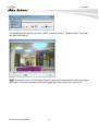


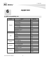


![Manual del usuario - [ [ [ ANSEL ] ] ]](http://vs1.manualzilla.com/store/data/006306298_1-4b727a9f513ab88544573091f86e1211-150x150.png)