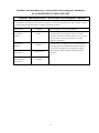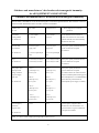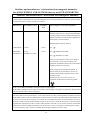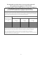
1
Touchmonitor User Guide
1928L 19” LCD Desktop Touchmonitor
5000 Series
User Guide
1928L 19” LCD Desktop Touchmonitor
Revision E
P/N E116103
Copyright © 2008 Tyco Electronics Corporation. All Rights Reserved.
No part of this publication may be reproduced, transmitted, transcribed, stored in a retrieval system,
or translated into any language or computer language, in any form or by any means, including,
but not limited to, electronic, magnetic, optical, chemical, manual, or otherwise without prior
written permission of Elo TouchSystems.
Disclaimer
The information in this document is subject to change without notice. Elo TouchSystems makes
no representations or warranties with respect to the contents hereof, and specifically disclaims
any implied warranties of merchantability or fitness for a particular purpose. Elo TouchSystems
reserves the right to revise this publication and to make changes from time to time in the content
hereof without obligation of Elo TouchSystems to notify any person of such revisions or changes.
Trademark Acknowledgments
Elo Touchsystems AccuTouch and IntelliTouch are trademarks of Tyco Electronics Corporation.
Other product names mentioned herein may be trademarks or registered trademarks of their respective companies.
iii
Warnings and Cautions
!
Warning
•
•
•
•
•
•
•
Danger - Explosion hazard. Do not use in the presence of flammable anesthetics, and other
flammable materials.
To prevent fire or shock hazards, do not immerse the unit in water or expose it to rain or
moisture.
Do not use the unit with an extension cord receptacle or other outlets unless the prongs of the
power cord can be fully inserted.
RISK OF ELECTRICAL SHOCK - DO NOT OPEN. To reduce the risk of electrical shock,
DO NOT remove the back of the equipment or open the enclosure. No user-serviceable parts
are inside. Refer servicing to qualified field service engineers only.
Uninsulated voltage within the unit may have sufficient magnitude to cause electrical shock.
Avoid contact with any part inside the unit.
This device complies with all applicable electromagnetic emission and immunity standards
for medical device equipment. This device is designed to not cause harmful interference, and
to accept any interference received, including interference that may cause undesired operation.
The performance of this device is limited to the emission and immunity standards that have
been applied. Other device which are not designed to withstand emission levels as specified
in the medical device standards may be susceptible to interference from this device.
Subjecting the device to conditions beyond the rated performance capabilities may result in
emissions in excess of the standard. If it is determined that this device produces
electromagnetic or other interference it must be disconnected from power until the cause of
the problem has been determined and resolved. If it is determined that this device is
functioning improperly due to electromagnetic and other interference it must be disconnected
from power until the cause of the problem has been determined and resolved.
Elo TouchSystems recommends that after its useful life (or after sustaining unrepairable
damage), customers dispose of the touchmonitor and its power supply in an environmentally
sound manner. Acceptable methods include the reuse of parts or whole products and the
recycling of products, components, and materials. Please consult and obey national state, and
local laws and ordinances governing the safe disposal of electronic equipment.
Note that the fluorescent lamps inside this product contain mercury and must be recycled or
disposed of according to local, state, or national laws. For more information, contact the
Electronic Industries Alliance at www.eiae.org.
This product consists of devices that may contain mercury, which must be recycled or disposed of
in accordance with local, state, or federal laws. (Within this system, the backlight lamps in the
monitor display contain mercury.)
iv
Caution
•
•
•
•
!
Power cord is used as a disconnection device. To de-energize equipment, disconnect the
power cord.
This unit must follow the national requirement and local state laws to dispose unit.
Before connecting the cables to your Elo touchmonitor, make sure all components are
powered OFF.
Only approved components complying with IEC60601-1 series can be connected to ET1928L
in Patient Environment. The use of ACCESSORY equipment not complying with the
equivalent safety requirements of this equipment may lead to a reduced safety of the resulting
system. Consideration relating to the choices of accessory equipment should include:· Use of
accessory in the patient environment.· Evidence that the safety certification of the accessory
has been performed in accordance to the appropriate IEC 60601-1 and/or IEC 60601-1-1 har
monized national standard.
For continued safety - This unit only complies to the above standards if used with a medical grade power cord.
-A medical grade power supply, such as the one specified, is required for use in a medical
application.
Note:
• This symbol alerts the user to important information concerning the operation and
maintenance of this unit, which should be read carefully to avoid problems.
• This symbol means DC Current.
• This symbol means ON/OFF stand-by switch.
v
!
CAUTION-Life Support
Care must be taken when this touchmonitor is a critical component of a life support system or
device. In case of failure of this touchmonitor, appropriate redundant systems should be
incorporated into the system or device to prevent injury to the user or patient.
The following should be an integral part of the safety design of a life support system or device
using this touchmonitor for a critical function.
• An alternate interface or fail-safe must be available should the touchscreen fail to operate.
• The touchscreen interface must not be the only means of control of a critical function.
• An alternate video display should be incorporated into the safety design if used to monitor a
critical function.
• The internal speakers of this touchscreen monitor must not be the sole method of warning of
a critical function.
Critical functions are:
1. Life support devices or systems are devices or systems which, (a) are intended for surgical
implant into the body, or (b) support or sustain life, or (c) whose failure to perform when
properly used in accordance with instructions for use provided in the labeling, can be reason
ably expected to result in significant injury to the user.
2. A critical component is any component of a life support device or system whose failure to
perform can be reasonably expected to cause the failure of the life support device or system,
or to affect its safety or effectiveness.
Definitions:
“ PATIENT ENVIRONMENT”
any environment in which intentional or unintentional contact can occur between a PATIENT
and parts of the ME EQUIPMENT or ME SYSTEM or between a PATIENT and other persons
touching parts of the ME EQUIPMENT or ME SYSTEM.
vi
Classification
With respect to electrical shock, fire in accordance with UL60601-1 and CAN/CSA C22.2 No.
60601-1
This monitor is a Class I (GROUNDED) DEVICE.
These displays are classified NO APPLIED PARTS EQUIPMENT.
Protection against harmful ingress of water:
INGRESS PROTECTION (IPX1)
This monitor shall be classified as ORDINARY EQUIPMENT, not intended or evaluated for use
in the presence of flammable anesthetic mixture with air, oxygen, or nitrous oxide.
Mode of Operation: CONTINUOUS OPERATION.
Temp.
Environmental conditions for transport and storage
o
o
Operating
0 C to 40 C
o
o
Storage / Transportation
-20 C to +60 C
Humidity (non-condensing)
Operating
Storage / Transportation
Altitude
Operating
Storage / Transportation
30% to 70%
10% to 90%
1060hpa.
0 to 40,000ft(12,192m)
Equivalent to 1013-303 hP.A
(14.7 to 4.4 psia)
For full Product Specifications refer to Appendix C
vii
European Standards and Classifications
Standards: EN 60601-1-2: 2001
The EMC limits and test methods are referred to the following standards:
Emission:
Immunity
CISPR 11: 2003+A1:2004
IEC 61000-4-2: 2001
AS/NZS CISPR 11:2004
IEC 61000-4-3: 2002+A1:2002
(Group 1, Class B)
IEC 61000-4-4: 2004
IEC 61000-4-5: 2001
EN55011: 1998+A1: 1999+
IEC 61000-4-6: 2003+A1:2004
A2: 2002, (Group 1, Class B)
IEC 61000-4-8: 2001
IEC 61000-4-11: 2004
IEC 61000-3-2: 2000,
(Refer to note * below)
IEC 61000-3-3; 1995+A1: 2001
Note *: The power consumption of EUT is 50.474W, which is less than 75W and no limits apply.
Therefore it is deemed to comply with IEC 61000-3-2: 2000 without any testing.
viii
Guidance and manufacturer’s declaration-electromagnetic immunityfor all EQUIPMENT AND SYSTEMS
Guidance and manufacturer’s declaration-electromagnetic emissions
The ET1928L is intended for use in the electromagnetic environment specified below. The customer or the user
of the ET1928L should assure that it is used in such an environment.
Emissions test
Compliance
RF emissions
CISPR 11
Group 1
RF emissions
CISPR 11
Class B
Harmonics emissions
IEC 61000-3-2
Not applicable
Voltage fluctuations/
flicker emissions
IEC 61000-3-3
Complies
Electromagnetic environment-guidelines
The ET1928L uses RF energy only for its internal
function. Therefore, its RF emissions are very low and
are not likely to cause any interference in nearby
electronic equipment.
The ET1928L is suitable for use in all establishments,
including domestic establishments and those directly
connected to the public low-voltage power supply
network that supplies buildings used for domestic
purposes.
ix
Guidance and manufacturer’s declaration-electromagnetic immunityfor all EQUIPMENT AND SYSTEMS
Guidance and manufacturer’s declaration-electromagnetic immunity
The ET1928L is intended for use in the electromagnetic environment specified below. The customer or the user
of the ET1928L should assure that it is used in such an environment.
Immunity test
IEC 60601
Compliance level
test level
Electromagnetic environmentguidelines
Electrostatic
± 6 kV contact
± 6 kV contact
discharge(ESD)
± 8 kV air
± 8 kV air
IEC 61000-4-2
Floors should be wood, concrete or
ceramic tile. If floors are covered with
synthetic material, the relative humidity
should be at least 30%.
Electrical Fast
± 2 kV for power
± 2 kV for power
Mains power quality should be that of a
transient/burst
supply lines
supply lines
typical commerical or hospital
IEC 61000-4-4
± 1 kV for input/output
± 1 kV for input/output
lines
lines
environment.
Surge
± 1 kV line(s) to line(s)
± 1 kV line(s) to line(s) Mains power quality should be that of a
IEC 61000-4-5
± 2 kV line(s) to earth
± 2 kV line(s) to earth
typical commerical or hospital
environment.
Voltage dips, short
<5% UT
<5% UT
Mains power quality be that of a
interruption and
(>95% dip in UT)
(>95% dip in UT)
typical commerical or hospital
voltage variations
for 0.5 cycle
for 0.5 cycle
on power supply
input lines
IEC 61000-4-11
Power frequency
environment. If the user of the ET1928L
requires continued operation during power
40% UT
40% UT
mains interruptions, it is recommended that
(60% dip in UT)
(60 % dip in UT)
the ET1928L be powered from an
for 5 cycles
for 5 cycles
uninterruptible power supply or a battery.
70% UT
70% UT
(30% dip in UT)
(30% dip in UT)
for 25 cycles
for 25 cycles
<5% UT
<5% UT
(>95% dip in UT)
(>95% dip in UT)
for 25 cycles
for 25 cycles
3 A/m
3A/m
(50/60 Hz)
Power frequency magnetic fields
should be at levels characteristic of a
magnetic field
typical location in a typical commerical
or hospital environment.
IEC 61000-4-8
NOTE UT is the a.c. mains voltage prior to application of the test level.
x
Guidance and manufacturer’s declaration-electromagnetic immunityfor all EQUIPMENT AND SYSTEMS that are not LIFE-SUPPORTING
Guidance and manufacturer’s declaration-electromagnetic immunity
The ET1928L is intended for use in the electromagnetic environment specified below. The user of the ET1928L
should assure that it is used in such an environment.
Immunity test
IEC 60601 test level
Compliance
level
Electromagnetic environment-guidelines
Portable and mobile RF communications equipment
should be used no closer to any part of theET1928L,
including cables, than the recommended separation
distance calculated from the equation applicable to
the frequency of the transmitter.
Recommended separation distance
Conducted RF
3 Vrms
3 Vrms
d=1.2 P
Radiated RF
IEC 61000-4-3
3 V/m
80 MHz to 2.5 GHz
3 Vrms
d=1.2 P 80MHz to 800 MHz
d=2.3 P 800 NHz to 2.5GHz
where P is the maximum output power rating of
the transmitter in watts (W) according to the
transmitter manufacturer and d is the recommended
separation distance in metres(m)
Filed strengths from fixed RF transmitters, as
determined by an electromagnetic site survey 3,
should be less than the compliance level in each
frequency range4.
Interference may occur in the vicinity of
equipment marked with the following symbol:
NOTE 1 At 80 MHz and 800 MHz, the higher frequency range applies.
NOTE 2 These guidelines may not apply in all situation. Electromagnetic propagation is affected by absorption and
reflection from structures, objects and people.
3.
Filed strengths from fixed transmitters, such as base stations for radio (cellular/cordless) telephones and land
mobile radios, amateur radio, AM and FM radio broadcast and TV broadcast cannot be predicted theoretically with
accuracy. To assess the electromagnetic environment due to fixed RF transmitters, an electromagnetic site survey
should be considered. If the measured filed strength in the location in which the ET1928L is used exceeds the
applicable RF compliance level above, the ET1928L should be observed to verify normal operation. If abnormal
performance is observed, additional measures may be necessary, such as reorienting or relocating the ET1928L.
4. Over the frequency range 150 kHz to 80 MHz, field strengths should be less than 3 Vrms.
xi
Recommended separation distance between portable and mobile
RF communications equipment and the ET1928L
for all EQUIPMENT AND SYSTEMS that are not LIFE-SUPPORTING
Recommended separation distances between portable
and mobile RF communications equipment and the ET1928L
The ET1928L is intended for use in an electromagnetic environment in which radiated RF disturbances are controlled.
The customer or the user of the ET1928L can help prevent electromagnetic interference by maintaining a minimum distance between portable and mobile RF communications (equipment) and the ET1928L as recommended
below according to the maximum output power of the communications equipment.
Separation distance according to frequency of transmitter
Rated maximum output
power of transmitter
W
150 kHz to 80 MHz
80MHz to 800 MHz
800 MHz to 2.5 GHz
d=1.2 P
d=1.2 P
d=2.3 P
0.01
0.12
0.12
0.23
0.1
0.37
0.37
0.74
1
1.2
1.2
2.3
10
3.7
3.7
7.4
100
12
12
23
For transmitters rated at a maximum output power not listed above, the recommended separation distance d in
metres(m) can be estimated using the equation applicable to the frequency of the transmitter, where P is the
maximum output power rating of the transmitter in watts(W) according to the transmitter manufacturer.
NOTE 1 At 80 MHz and 800 MHz, the separation distance for the higher frequency range applies.
NOTE 2 These guidelines may not apply in all situations. Electromagnetic propagation is affected by absorption
and reflection from structures, objects and people.
xii
Table of Contents
Warnings and Cautions ................................................. iv
Warning ................................................................. iv
Caution ................................................................... v
Caution-Life Support ..................................................... vi
Classification ................................................................ vii
European Standards and Classifications
Standards ............................................................ viii
Display Angle ................................................. 17
Chapter 4
TROUBLESHOOTING
19
Solutions to Common Problems ................................. 19
Appendix A
Chapter 1
INTRODUCTION
Power Display & Power Saving ............................ 17
General Power Saving Mode ........................ 17
1
Product Description ................................................ 1
LCD Display Performance Features ....................... 2
19 inch TFT LCD Display Panel ...................... 2
External Medical Grade Power Supply ............ 2
NATIVE RESOLUTION
21
Appendix B
TOUCHMONITOR SAFETY
23
Care and Handling of Your Touchmonitor ................... 24
Appendix C
Chapter 2
INSTALLATION AND SETUP
3
Unpacking Your Touchmonitor ............................... 3
Product Overview ........................................... 4
Main Unit ......................................................... 4
Back Unit ......................................................... 4
Side View ......................................................... 4
Base Bottom View ........................................... 5
KensingtonTM Lock ........................................... 5
Touch Interface Connection .................................... 6
Step 1 Connecting the Video Cable ................ 6
Step 2 Connecting the Serial/USB Cable ........ 7
Step 3 Connecting the Speaker Cable ............ 8
Step 4 Connecting the Power Cable ............... 9
TECHNICAL SPECIFICATIONS
25
Display Modes ............................................................. 25
Touchmonitor Specifications ........................................ 26
Power Supply Cord Selection ...................................... 27
North America ....................................................... 27
Cord selection for other than North America ........ 28
AccuTouch (resistive) Touchscreen Specifications ..... 30
IntelliTouch (acoustic) Touchscreen Specifications ..... 31
Acoustic Pulse Recognition Specification .................... 32
Appendix D
CONTACT ELO
33
Contact Elo
............................................................. 33
Mounting the Display ............................................ 10
Rear Mounting Using the VESA Interface ............ 11
VESA Mounting Options ....................................... 11
REGULATORY INFORMATION
35
Optimizing the LCD Display .................................. 12
WARRANTY
39
Installing the Touch Driver Software ..................... 12
Installing APR USB Touch Driver for
INDEX
41
Windows XP .................................................. 12
Chapter 3
OPERATION
13
About Touchmonitor Adjustments ................................ 13
Side Panel Controls ....................................... 14
Controls and Adjustment ...................................... 15
OSD Menu Functions .................................... 15
OSD Locking and Unlocking Feature ............ 15
OSD Control Options ..................................... 16
CHAPTER
1
INTRODUCTION
Product Description
The 1928L is a medical display designed to present information to the operator and the customer.
The 1928L is available in serial and USB(combo) touch interface as well as non-touch. The
1928L functionally consists of a 19” LCD main display with a touchscreen. The main display
element is a 19” diagonal SXGA resolution (1280 x 1024) LCD display. The display consists of
an LCD display and touchscreen. The 1928L is powered by 12 VDC from an external medical
grade power source.
1-1
LCD Display Performance Features
19” TFT LCD Display Panel
Display format
Display area
Pixel pitch
Contrast Ratio
Brightness
LCD
AccuTouch
IntelliTouch
Accutouch transmission
Intellitouch transmission
Response time
Display color
Typical vertical viewing angle
Typical horizontal viewing angle
1280 x 1024
376.32 mm (H) x 301.056 mm (V)
0.294 mm (H) x 0.294 mm (V)
1300:1( typical)
300 cd/m2 (typical)
246 cd/m2 (typical)
276 cd/m2(typical)
82% (typical)
92% (typical)
Tr = 15 msec / Tf = 5 msec typical;
12 ms gray to gray response
16.7 million colors
89 deg (down) / 89 deg ( up)
89 deg (left) / 89 deg (right)
External Medical Grade Power Supply
The 1928L is powered by an external medical grade universal input AC power source.
Power supply:
• AC power: Input voltage 100 -240 VAC, 1.0A
• Input frequency 50/60 Hz
• DC output Voltage/Current: 12 VDC/4.0A
• Load regulation: ±5% Max.
• Line regulation: ±1% Max.
1-2
Elo Touchmonitor User Guide
CHAPTER
2
INSTALLATION AND SETUP
This chapter discusses how to install your LCD touchmonitor and how to install Elo TouchSystems
driver software.
Unpacking Your Touchmonitor
Check that the following items are present and in good condition:
LCD monitor
VGA cable
Serial Cable
European power cable
(not included on APR models)
USB cable
Power cable US/Canada
Elo QuickStart
CD
Software
DVI Cable
CD and Quick Install Guide
Power adaptor
2-3
Product Overview
Main Unit
Back Unit
Side View
2-4
Elo Touchmonitor User Guide
Base Bottom View
KensingtonTM Lock
The KensingtonTM lock is a security device that prevents theft. To find out more about this security device, go to http://www.kensington.com.
2-5
Touch Interface Connection
Note:
Before connecting the cables to your touchmonitor and PC, be sure that the computer
and touchmonitor are turned off.
STEP 1-Connecting the Video Cable
CONNECTIONS ON UNDERSIDE
VIDEO PORT
FEMALE 15-PIN
VIDEO CONNECTOR
VIDEO CABLE
•
•
•
•
Tilt the screen up and back to access the connection ports.
Connect the 15-pin video cable (the ferrite bead end) or 24-pin DVI-D cable to the video
port on your PC.
Connect the other end of the video cable to the video connector on your touchmonitor.
Secure the cable to your touchmonitor and PC by turning the screws on the connector
clockwise.
2-6 Elo Touchmonitor User Guide
STEP 2-Connecting the Serial and USB Touchscreen Cable
CONNECTORS ON THE UNDERSIDE
USB CONNECTOR
FEMALE 9-PIN SERIAL
TOUCHSCREEN CONNECTOR
SERIAL TOUCHSCREEN CABLE
•
•
•
•
Connect the female end of the serial (RS-232) cable to the serial port on your PC, or
connect the USB( ) touchscreen cable to the USB( ) touchscreen connector on the back
of your touchmonitor.
Connect the male end of the cable to the serial touchscreen connector on your
touchmonitor, or connect the other end of the USB( ) touchscreen cable to your PC.
Secure the cable to your touchmonitor and PC by turning the screws on the connector.
Please note that you can only have the usb or the serial feature connected. You can not
have both connected at the same time.
2-7
STEP 3-Connecting the Speaker Cable
CONNECTIONS ON UNDERSIDE
SPEAKER
PORT
SPEAKER CABLE
•
•
Connect the light blue end of the speaker cable to the light blue speaker port to the monitor
(audio in).
Connect the lime (light green) end of the speaker cable to the lime speaker port on the
computer (audio out).
2-8 Elo Touchmonitor User Guide
STEP 4-Connecting the Power Cable
CONNECTIONS ON UNDERSIDE
POWER
POWER CABLE
Depending on where you live, you will use either the European or US/Canadian power cable.
• Connect the female end of the power cable to the medical grade power adaptor.
• Connect the brick power cable into the power port on the touchmonitor.
• Route the cable through the cable management channel.
NOTE: To protect your equipment against risk of damage from electrical surges in the power line,
plug the touchmonitor’s power cord into a surge protector, and then connect the surge
protector to a grounded AC electrical outlet.
2-9
Mounting the Display
Your medically certified touchscreen display conforms to the VESA Flat Panel Monitor Physical
Mounting Interface (FPMPMI) standard. The FPMPMI standard defines a physical mounting
interface for flat panel displays. Your display conforms to the corresponding standards for flat
panel display mounting devices, such as for walls and table arms. The VESA mounting interface
is located on the back of your touchscreen display and is pre-connected to the pedestal.
Figure : VESA mounting interface location, pedestal removedˆ
1 Screw location, M4 Phillips, ×4
Note:You will need a Phillips screwdriver to mount the display or remove the pedestal.
2-10 Elo Touchmonitor User Guide
Rear Mounting Using the VESA Interface
1 If the display is already connected to a pedestal, remove the four screws that connect the
pedestal to the display (refer to Figure2-1 , item 1 ). Separate the pedestal from the display.
2 Reinstall the four screws into the VESA interface mount. Ensure that the monitor is
positioned with the correct side up.
3 Mount the monitor to the wall according to the template shown in Figure 2-2. Route the
cables through the cable access opening (Figure2-2, item 1 ).
1
Figure 2-2: Rear mount template (not to scale)
VESA Mounting Options
The following companies provide VESA mounting devices compatible with your touchscreen
monitor:
GCX
800-228-2555
707-773-1100
www.gcx.com
Ergotron
800-888-8458
651-681-7600
www.ergotron.comˆ
Innovative Office Products
800-524-2744
610-253-9554
www.innov-office-prod.com
MRI
800-688-2414
www.mediarecovery.com
2-11
Optimizing the LCD Display
To ensure the LCD display works well with your computer, configure the display mode of your
graphic card to make it less than or equal to 1280 x 1024 resolution, and make sure the timing of
the display mode is compatible with the LCD display. Refer to Appendix A for more information
about resolution. Compatible video modes for your touchmonitor are listed in Appendix C.
Installing the Touch Driver Software
Elo TouchSystems provides driver software that allows your touchmonitor to work with your
computer. Drivers are located on the enclosed CD-ROM for the following operating systems:
• Windows XP
• Windows 2000
• Windows Me
• Windows 98
• Windows 95
• Windows NT 4.0
• CE 2.x, 3.0, 4x
• Windows XP Embedded
• Windows 3.x
• MS DOS
• OS/2
Additional drivers and driver information for other operating systems (including Macintosh and
Linux) are available on the Elo TouchSystems web site at www.elotouch.com. Your Elo USB
touchmonitor is plug-and-play compliant. Information on the video capabilities of your
touchmonitor is sent to your video display adapter when Windows starts. If Windows detects
your touchmonitor, follow the instructions on the screen to install a generic plug-and-play monitor.
Refer to the appropriate following section for driver installation instructions.
Installing APR USB Touch Driver for Windows XP
Insert the ELO APR CD-ROM in your computer’s CD-ROM driver.
Follow the directions on the screen to complete the APR 2.0 driver setup for your
version of Windows.
1 Click Start > Run.
2 Click the Browse button to locate the SW600117.exe program on the CD-ROM.
3 Click Open, then OK to run SW600117.exe.
4 Follow the directions on the screen to complete the driver setup for your version
of Windows.
2-12
Elo Touchmonitor User Guide
CH APTER
3
OPERATION
About Touchmonitor Adjustments
Your touchmonitor will unlikely require adjustment. Variations in video output and application
may require adjustments to your touchmonitor to optimize the quality of the display.
For best performance, your touchmonitor should be operating in native resolution, that is 1280 x
1024 at 60-75 Hz. Use the display control panel in Windows to choose 1280 x 1024 resolution.
Operating in other resolutions will degrade video performance. For further information, please
refer to Appendix A. All adjustments you make to the controls are automatically memorized.
This feature saves you from having to reset your choices every time you unplug or power your
touchmonitor off and on. If there is a power failure your touchmonitor settings will not default to
the factory specifications. To restore factory set up, choose it from the OSD. See page 14, Recall
Defaults.
3-13
Side Panel Controls
1
2
3
4
5
Control
1 Menu/Exit
2
3
4 Select
5 Power Switch
3-14 Elo Touchmonitor User Guide
Function
Display/Exits the OSD menus.
1. Enter contrast of the OSD.
2. Increase value of the adjustment item.
3. Shuffle item clockwise.
1. Enter audio volume adjustment.
2. Decrease value of the adjustment item.
3. Shuffle item counter-clockwise.
1.Select the adjustment items from the OSD menu.
2. Enter “Auto Adjust” feature. (VGA mode only)
Switches the power of the monitor from off to on to off.
(Important note: Includes integrated power down delay function,
user must depress power button for five (5) seconds when powering
off)
Controls and Adjustment
OSD Menu Functions
To Display and Select the OSD Functions:
1 Press the Menu key to activate the OSD menu.
2 Use or to move clockwise or counterclockwise through the menu. Press the select key
on the monitor. The parameter will be highlighted when selected.
3 To quit the OSD screen at any time during the operation, press the Menu key. If no keys are
pressed for a short time period, the OSD automatically disappears.
NOTE:
The OSD screen will disappear if no input activities are detected from 45 seconds to 255
seconds, depending on the OSD time setting on the OSD of the monitor. The monitor
default is 45 seconds.
OSD Locking and Unlocking Feature
•
To Lock OSD, hold Menu and Up Button for 2 seconds. A window pops up showing “OSD
unlock” as you hold every 2 seconds the window toggles from “OSD is unlock” to “OSD
Lock”.
•
To Lock Power, hold Menu and Down for 2 seconds. A window pops up showing “Power
unlock” as you hold every 2 seconds the window toggles from “Power unlock” to “Power
Lock”.
•
While the OSD and or Power is locked, when the OSD keys are pushed no window shall
appear.
3-15
OSD Control Options
Control
Contrast
Brightness
V-Position
H-Position
Recall Defaults
Color Balance
Audio Volume
Sharpness
Phase
Clock
OSD H-Position
OSD V-Position
OSD Time
Auto-Adjust
OSD Language
Input Select
3-16
Elo Touchmonitor User Guide
Description
Increases or decreases contrast.
Increases or decreases brightness.
Moves the screen up or down.
Moves the screen left or right.
Returns the monitor to its default settings.
Press or and “Select” button to select 9300, 6500, 5500, 7500
and USER. Only when selecting USER can you make adjustments
to the R/G/B content. Press Select to restore to factory default setting.
Adjust audio volume of OSD menu.
Adjust Sharpness.
Increases or decreases the snow noise of the image after auto
adjustment is made.
The dot clock is fine-adjusted after auto adjust.
Moves the OSD position horizontally on the screen. When the
“SELECT” button and the
button is pressed, the OSD control
menu will move to the right side of the screen. Likewise, when the
“Select” button and the
button is pressed, the OSD control
menu will move to the left side.
Moves the OSD position vertically on the screen. When the
“SELECT” button and the button is pressed, the OSD control
menu will move to the top side of the screen. Likewise, when the
“Select” button and the
button is pressed, the OSD control
menu will move to the lower side.
Adjusts the time of OSD icon stays on monitor.
(1)Press Auto to enable this function. The Auto-Adjust will
automatically adjust V-Position, H-Position, Clock and Clock-Phase.
(VGA only)
(2)Indicates the current resolution, H-Frequency and V-Frequency.
(DVI and VGA)
Select from English, French, German, Spanish, Japanese, Italian,
Chinese, Polish and Swedish.
Select video source from DSUB analog to DVI digital.
Power Display & Power Saving
General Power Saving Mode
Power
Consumption
48w max.
7w max.
4w
Mode
On
Sleep
Off
Power-Save (No Input)
• The LCD panel background is cut when there is no signal input (AC line power consump
tion of 7w or less).
Note:
If the monitor is not to be used for an extended period of time, it is recommended
that the monitor be turned off.
Display Angle
For viewing clarity, you can tilt the LCD forward (up to -5 degrees) or backward (up to 90
degrees).
CAUTION
• In order to protect the LCD, be sure to hold the base when adjusting the LCD.
• For models without a touchscreen take care not to touch the screen.
3-17
3-18
Elo Touchmonitor User Guide
CHAPTER
4
TROUBLESHOOTING
If you are experiencing trouble with your touchmonitor, refer to the following table. If the problem persists, please contact your local dealer or our service center. Elo Technical Support numbers are listed on page 31 of this manual.
Solutions to Common Problems
Problem
The monitor does not respond
Characters on the screen are dim
The screen is blank
OSD or power buttons don’t work
“Out of Range” display”
Touch doesn’t work
Power will not shut off immediately
Suggestion(s)
Check that the monitor’s Power Switch is on. You turn on the
system.Turn off the power and check the monitor’s power cord
and signal cable for proper connection.
Refer to the Controls and Adjustments section to adjust the brightness.
During operation, the monitor screen may automatically turn off as
a result of the Power Saving feature. Press any key to see if the
screen reappears.
Refer to the Controls and Adjustments section to adjust the brightness.
Check to see that they are not locked. See page 15.
Check to see of the resolution or vertical frequency of your
computer is higher than that of the LCD display.
Reconfigure the resolution of your computer to make it less than or
equal to 1280 x 1024. 1280 x 1024 is optimal. See Appendix A for
more information on resolution.
Make sure cable is securely attached at both ends.
Be sure to depress power button for five(5) seconds when powering
off. Unit includes integrated power down delay function.
4-19
4-20
Elo Touchmonitor User Guide
APPENDIX
A
NATIVE RESOLUTION
The native resolution of a monitor is the resolution level at which the LCD panel is designed to
perform best. 1928L native resolution is 1280 x 1024. In almost all cases, screen images look
best when viewed at their native resolution. You can lower the resolution setting of a monitor but
not increase it.
Input Video
640 x 480 (VGA)
800 x 600 (SVGA)
1024 x 768 (XGA)
1280 x 1024 (SXGA)
19.0” LCD
Transforms input format to 1280 x 1024
Transforms input format to 1280 x 1024
Transforms input format to 1280 x 1024
Display in Native Resolution
The native resolution of an LCD is the actual number of pixels horizontally in the LCD by the
number of pixels vertically in the LCD. LCD resolution is usually represented by
the following symbols:
VGA
SVGA
XGA
SXGA
640 x 480
800 x 600
1024 x 768
1280 x 1024
A-21
As an example, a SVGA resolution LCD panel has 800 pixels horizontally by 600 pixels
vertically. Input video is also represented by the same terms. XGA input video has a format
of 1280 pixels horizontally by 1024 pixels vertically. When the input pixels contained in
the video input format match the native resolution of the panel, there is a one to one correspondence of mapping of input video pixels to LCD pixels. As an example, the pixel in
column 45 and row 26 of the input video is in column 45 and row 26 of the LCD. For the
case when the input video is at a lower or higher resolution than the native resolution of the
LCD, the direct correspondence between the video pixels and the LCD pixels is lost. The
LCD controller can compute the correspondence between video pixels and LCD pixels
using algorithms contained on its controller. The accuracy of the algorithms determines the
fidelity of conversion of video pixels to LCD pixels. Poor fidelity conversion can result in
artifacts in the LCD displayed image such as varying width characters.
A-22
Elo Touchmonitor User Guide
APPENDIX
B
TOUCHMONITOR SAFETY
This manual contains information that is important for the proper setup and maintenance of your
touchmonitor. Before setting up and powering on your new touchmonitor, read through this
manual, especially Chapter 2 (Installation), and Chapter 3 (Operation).
1.
2.
3.
4.
5.
To reduce the risk of electric shock, follow all safety notices and never open the
touchmonitor case.
Turn off the product before cleaning
Your new touchmonitor is equipped with a 3-wire, Hospital Grade grounding power
cord. The power cord plug will only fit into a grounded outlet. Do not attempt to fit
the plug into an outlet that has not been configured for this purpose. Do not use a
damaged power cord. Use only the power cord that comes with your Elo
TouchSystems Touchmonitor. Use of an unauthorized power cord may invalidate
your warranty.
The slots located on the sides and top of the touchmonitor case are for ventilation.
Do not block or insert anything inside the ventilation slots.
It is important that your touchmonitor remains dry. Do not pour liquid into or onto
your touchmonitor. If your touchmonitor becomes wet do not attempt to repair it
yourself.
B-23
Care and Handling of Your Touchmonitor
The following tips will help keep your Elo touchmonitor functioning at the optimal level.
• To avoid risk of electric shock, do not disassemble the external power adaptor or display
unit cabinet. The unit is not user serviceable. Remember to unplug the display unit from
the power outlet before cleaning.
• Do not use alcohol (methyl, ethyl or isopropyl) or any strong dissolvent. Do not use
thinner or benzene, abrasive cleaners or compressed air.
• To clean the display unit cabinet, use a cloth lightly dampened with a mild detergent.
• Avoid getting liquids inside your touchmonitor. If liquid does get inside, have a qualified
service technician check it before you power it on again.
• Do not wipe the screen with a cloth or sponge that could scratch the surface.
• To clean the touchscreen, use window or glass cleaner. Put the cleaner on a soft cloth and
wipe the touchscreen. Never apply the cleaner directly on the touchscreen .
Warning
This product consists of devices that may contain mercury, which must be recycled or
disposed of in accordance with local, state, or federal laws. (Within this system, the
backlight lamps in the monitor display contain mercury.)
Waste Electrical and Electronic Equipment(WEEE) Directive
In the European Union, this label indicates that this product should not be disposed
of with household waste. It should be deposited at an appropriate facility to enable
recovery and recycling.
B-24
Elo Touchmonitor User Guide
APPENDIX
C
TECHNICAL SPECIFICATIONS
Display Modes
Your Elo touchmonitor is compatible with the following standard video modes:
Item
1
2
3
4
5
6
7
8
9
10
11
12
13
14
15
16
17
18
19
Resolution
640 x 350
720 x 400
640 x 480
640 x 480
640 x 480
640 x 480
800 x 600
800 x 600
800 x 600
800 x 600
832 x 624
1024 x 768
1024 x 768
1024 x 768
1024 x 768
1280 x 1024
1280 x 1024
1152 x 864
1280 x 960
Type
VGA
VGA
VGA
MAC 66
VESA 72
VESA 75
VESA 56
VESA 60
VESA 75
VESA 72
MAC 75
VESA 60
SUN 65
VESA 70
VESA 75
SXGA
SXGA
SXGA
SXGA
H.Scan(KHz) V. Scan(Hz)
31.47
70
31.47
70
31.47
60
35
66
37.86
72
37.5
75
35.16
56
37.88
60
46.88
75
48.08
72
49.72
75
48.36
60
52.45
65
56.48
70
60.02
75
64
60
80
75
67.5
75
60
60
Polarity
+/-/+
-/-/ -/ -/+/+
+/+
+/+
+/+
-/-/-/-/+/+
+/+
+/+
+/+
+/+
C-25
Touchmonitor Specifications
Parameter
LCD Display
Pixel Pitch
Display Mode
Native
Contrast Ratio
Brightness
LCD
AccuTouch
IntelliTouch
Response Time
Display Color
Viewing Angle
Input Signal
Signal Connector
Front Control
Value
19.0” TFT Active Matrix Panel
0.294(H) x 0.294(V) mm
VGA 640 x 350 (70 Hz)
VGA 720 x 400 (70 Hz)
VGA 640 x 480 (60 / 72 / 75 Hz)
SVGA 800 x 600 (56 / 60 / 72 / 75 Hz)
SXGA 1280 x 1024 (60,70,75 Hz)
SXGA 1280 x 1024
1300 : 1 (typical)
300 cd/m2 with AT 246 cd/m2, IT 276 cd/m2, IR 276 cd/m2
300 cd/m2 (typical)
246 cd/m2 (typical)
276 cd/m2 (typical)
Tr = 15 msec, Tf = 5 msec typical ; 12 ms gray to gray
16.7 million color, 6 bit with dithering
o
o
o
o
(L/R)= -89 /+89 (typical), (U/D) -89 /+89 (typical)
VGA Analog Video R.G.B. Analog 0.7V peak to peak
Sync TTL Positive or Negative, Composite Sync, Sync on green
DVI Video Digital TMDS Input
15 Pin D-Sub, DVI-D
Power ON / OFF, Menu, Select OSD Contrast, Brightness, H/VPosition, Recall default, Color Temperature, Sharpness, Phase, Clock
OSD H/V position, OSD Time, Auto Adjust, OSD Language,
Input Select
DDC1 / 2B
AccuTouch , IntelliTouch, APR
Plug & Play
Touch Panel
Power
External Power Supply*
AC 100-240V, 50/60 Hz/1.0A
Monitor
DC 12V, 4A
Environmental
o
o
Temp. Operating
0 C to 40 C
o
o
Storage/Transportation -20 C to +60 C
Humidity (non-condensing)
Operating
30% to 70%
Storage/Transportation 10% to 90%
Altitude Operating
1060hpa
Storage/Transportation 0 to 40,000ft (12,192m)
Equivalent to 1013-303 hP.A
(14.7 to 4.4 psia)
Dimensions (H x W x D) 429 x 390 x 212 mm
Weight (Net)
8.4kg.
Certifications
UL/cUL(UL 60601-1:2003), FCC, CE, VCCI, C-TICK, IPX1, CB,
Argentina S-mark, Medical Directive, EN 60601-1:2001, CISPR II: 2003+
A1: 2004 Class B, IEC 60529:1989+ A1:1999, CCC, MIC, EK
* FOR CONTINUED SAFETY - Use only with Hitron Model HES49-12040 adaptor.
C-26
Elo Touchmonitor User Guide
Power Supply Cord Selection
North America
Power Supply Cord Detachable, UL Listed, Type SJT 3 conductor, 18 AWG, configured load
fittings terminating in molded on parallel blade. Grounding type hospital grade attachment plug,
rated at a minimum of 3 amperes.
Basic Cord Type
SP-2
SP-3
SV
SJ
S
Equivalent Types
SPE-2, SPT-2
SPE-3, SPT-3
SVE, SVO, SVOO, SVT, SVTO, SVTOO
SJE, SJO, SJOO, SJT, SJTO, SJTOO
SE, SO, SOO, ST, STO, STOO
Grounding reliability can only be achieved when the EQUIPMENT is connected to an equivalent
receptacle marked “Hospital Only” or “Hospital Grade”.
Auxiliary Cable Selection
Europe and Asia
Only IEC 60601-1 EMC compliant cables may be used.
Power Supply
Use only a medical grade power supply such as HiTRON HES49-12040.
Accessory Kit
Item
1
2
3
4
5
6
7
8
9
10
11
Description
One(1) Elo TouchTools CD part number 450261-000(latest verision)
One(1) black US medical power cable, 3.0M
One(1) black European power cable, 1.8M
One(1) black serial cable PC99 compliant
One(1) black USB cable PC99 compliant
One(1) black VGA video cable PC99 compliant
One (1) DVI-D video cable PC99 compliant
One(1) Quick Start Guide
Two(2) desiccant/dryer packs-include one(1) in monitor bag
and one(1) in accessory bag
One(1) black Medical grade power adaptor
Primary source-Hitron
One(1) black Audio cable
P/N
821500101801
5330030005F0
5330005203F0
5313118016F0
5313118023F0
5313018028F0
5313118025F0
821107600101
810400200102
810400300102
3316000022F0
5313118019F0
C-27
Cord selection for other than North America
For 100 V ac or 220/230/240 V ac operation, the unit is provided with IEC 320 flexible power
cords properly configured for the intended country other than North America. The NOMINAL
cross-sectional area (mm2 Cu) must be 0,75. For assistance in selecting the proper power cord
contact the Elo distributor in your area or contact Elo (see Appendix D, page 23)
C-28
Country
Cert.
Agency
Argentina
IRAM
IrelandNSAI
Australia
SAA
Italy
IMQ
Austria
OVE
Japan
MITI
Beligum
CEBEC
Netherlands KEMA
Canada
CSA
Japan
MITI
China
CCEE
Norway
NEMKO
Denmark
DEMKO
Sweden
SEMKO
Finland
FEI
Switzerland SEV
France
UTE
United
Kingdom
Germany
VDE
Elo Touchmonitor User Guide
Mark
Cert
Country
Agency
ASTA
BSI
Mark
HAR FLEXIBLE CORD
Approval Organization
Printed or Embossed
Harmonization Marking
be Located On Jacket or
Insulation of Internal Wiring)
Alternative Marking
(May Utilizing Black-Red
Yellow Thread (Length
of color Section, mm)
Comite Electrotechnique
Belge (CEBEC)
CEBEC
<HAR>
10
30
10
Verband Deutscher Elektrotechniker (VDE) e.V.
Prufstelle
<VDE>
<HAR>
30
10
10
USE
<HAR>
30
10
30
IEMMEQU
<HAR>
10
30
50
BASEC
<HAR>
10
10
30
KEMA-KEUR
<HAR>
10
30
30
SEMKO AB Svenska Elektriska
Materielkontrollanstalter
SEMKO
<HAR>
10
10
50
Österreichischer Verband fur Elektrotechnik
(ÖVE)
<ÖVE>
<HAR>
30
10
50
<DEMKO>
<HAR>
30
10
30
National Standards Authority of Ireland (NSAI)
<NSAI>
<HAR>
30
30
50
Norges Elektriske Materiellkontroll (NEMKO)
NEMKO
<HAR>
10
10
70
Asociacion Electrotecnica Y Electronica Espanola
(AEE)
<UNED>
<HAR>
30
10
70
Hellenic Organization for Standardization (ELOT)
ELOT
<HAR>
30
30
70
np
<HAR>
10
10
90
Schweizerischer Elektro Technischer Verein
(SEV)
SEV
<HAR>
10
30
90
Elektriska Inspektoratet
SETI
<HAR>
10
30
90
Union technique de l'Electricite (UTE)
Instituto Italiano del Marchio di Qualita (IMQ)
British Approvals Service for Electric Cables
(BASEC)
N> V. KEMA
Danmarks Elektriske Materialkontroll
Instituto Portages da Qualidade (IPQ)
C-29
AccuTouch (resistive) Touchscreen Specifications
Mechanical
Positional Accuracy
Standard deviation of error is less than 0.080 in. (2.03 mm).
Equates to less than ±1%.
Touchpoint Density
More than 100,000 touchpoints/in2(15,500 touchpoints/cm2)
Touch Activation Force
Typical less than 3 ounces(85 grams)
Surface Durability
Expected Life Performance
Surface durability is that of glass, Mohs’hardness rating of 7.
No known wear-out mechanism, as there are no layers,
coatings, or moving parts. IntelliTouch technology has been
operationally tested to more than 50 million touches in one
location without failure, using a stylus similar to a finger.
Sealing
Unit is sealed to protect against splashed liquids, dirt, and
dust.
Optical
Light Transmission (per ASTM 90%
D1003)
C-30
Visual Resolution
All measurements made using USAF 1951 Resolution Chart,
under 30X magnification, with test unit located approximately
1.5 in (38 mm) from surface of resolution chart. Clear surface:
Excellent, with no noticeable degradation. Antiglare surface:
6:1 minimum.
Gloss (per ASTM D2457 using
a 60-degree gloss meter)
Antiglare surface: Curved: 60± 20 gloss units or 75 ±15 gloss
units.
Environmental
Chemical Resistance
The active area of the touchscreen is resistant to all
chemicals that do not affect glass, such as:
Acetone, Toluene, Methyl ethyl ketone, Isopropyl alcohol,
Methyl alcohol, Ethyl acetate, Ammonia-based glass cleaners,
Gasoline, Kerosene, Vinegar
Electrostatic Protection (per
EN 61 000-4-2, 1995)
Meets Level 4 (15 kV air/8 kV contact discharges).
Elo Touchmonitor User Guide
IntelliTouch (surface acoustic wave) Touchmonitor Specifications
Mechanical
Positional Accuracy
Touchpoint Density
Touch Activation
Force
Surface Durability
Expected Life
Performance
Sealing
Optical
Light Transmission
(per ASTM D1003)
Visual Resolution
Gloss (per ASTM
D2457 using a 60degree gloss meter)
Standard deviation of error is less than 0.080 in. (2.03 mm).
Equates to less than ±1%.
More than 100,000 touchpoints/in2 (15,500 touchpoints/cm2).
Typically less than 3 ounces (85 grams).
Surface durability is that of glass, Mohs’hardness rating of 7.
No known wear-out mechanism, as there are no layers, coatings,
or moving parts. IntelliTouch technology has been operationally
tested to more than 50 million touches in one location without failure,
using a stylus similar to a finger.
Unit is sealed to protect against splashed liquids, dirt, and dust.
IntelliTouch 92%, AccuTouch 82%.
All measurements made using USAF 1951 Resolution Chart, under
30X magnification, with test unit located approximately 1.5 in (38
mm) from sur face of resolution chart. Clear surface: Excellent, with
no noticeable degradation. Antiglare surface: 6:1 minimum.
Antiglare surface: Curved: 60 ±20 gloss units or 75 ± 15 gloss units.
C-31
Acoustic Pulse Recognition Specification
MECHANICAL
Input method
ELECTRICAL
Position accuracy
Resolution accuracy
Touch activation force
Controller
OPTICAL
Light transmission
ENVIRONMENTAL
Chemical resistance
DURABILITY
Surface durability
Expected life
C-32
Elo Touchmonitor User Guide
Finger, finger nail, gloved hand, or stylus activation
1% max. error
Touchpoint density is based on controller resolution of
4096 x 4096
Typically 2 to 3 ounces (55 to 85 grams)
Board: USB 1.1
90%+/-5%
The touch activation area of the touchscreen is resistant to
chemicals that do not affect glass such as: acetone, toluene,
methyl ethyl ketone, isopropyl alcohol, methyl alcohol,
ethyl acetate, ammonia-based glass cleaners, gasoline,
kerosene, vinegar
Surface durability is that of glass, Mohs’ hardness rating
of 7
No known wear-out mechanism, as there are no layers,
coatings, or moving parts. APR technology has been op
erationally tested to more than 50 million touches in one
location without failure, using a stylus similar finger.
APPENDIX
D
Contact Elo
Elo TouchSystems
301 Constitution Drive
Menlo Park, CA 94025
1-800-ELO-TOUCH
(1-800-356-8682)
www.elotouch.com
D-33
D-34 Elo Touchmonitor User Guide
REGULATORY INFORMATION
I. Electrical Safety Information:
A) Compliance is required with respect to the voltage, frequency, and current requirements
indicated on the manufacturer’s label. Connection to a different power source than those
specified herein will likely result in improper operation, damage to the equipment or pose a
fire hazard if the limitations are not followed.
B) There are no operator serviceable parts inside this equipment. There are hazardous
voltages generated by this equipment which constitute a safety hazard. Service should be
provided only by a qualified service technician.
C) This equipment is provided with a detachable power cord which has an integral safety
ground wire intended for connection to a grounded safety outlet.
1) Do not substitute the cord with other than the provided approved type. Under no
circumstances use an adapter plug to connect to a 2-wire outlet as this will defeat the
continuity of the grounding wire.
2) The equipment requires the use of the ground wire as a part of the safety certification,
modification or misuse can provide a shock hazard that can result in serious injury or
death.
3) Contact a qualified electrician or the manufacturer if there are questions about the
installation prior to connecting the equipment to mains power.
II. Emissions and Immunity Information
A) Notice to Users in the United States: This equipment has been tested and found to comply
with the limits for a Class B digital device, pursuant to Part 15 of FCC Rules. These limits are
designed to provide reasonable protection against harmful interference in a residential
installation. This equipment generates, uses, and can radiate radio frequency energy, and if
not installed and used in accordance with the instructions, may cause harmful interference to
radio communications.
B) Notice to Users in Canada: This equipment complies with the Class B limits for radio noise
emissions from digital apparatus as established by the Radio Interference Regulations of
Industrie Canada.
C) Notice to Users in the European Union: Use only the provided power cords and
interconnecting cabling provided with the equipment. Substitution of provided cords and
cabling may compromise electrical safety or CE Mark Certification for emissions or
immunity as required by the following standards:
This Medical Electrical Equipment is required to have a CE Mark on the manufacturer’s
label which means that the equipment has been tested to the following Directives and
Standards: This equipment has been tested to the requirements for the CE Mark as re
quired by medical device Directive (MDD) 93/42/EEC indicated in European Standard
EN60601-1 and EN60601-1-2 (including EN55011 Class B).
35
D) General Information to all Users: This equipment generates, uses and can radiate radio frequency energy. If not installed and used according to this manual the equipment may cause
interference with radio and television communications. There is, however, no guarantee that
interference will not occur in any particular installation due to site-specific factors.
1) In order to meet emission and immunity requirements, the user must observe the following:
a) Use only the provided I/O cables to connect this digital device with any computer.
b) To ensure compliance, use only the provided manufacturer’s approved line cord.
c) The user is cautioned that changes or modifications to the equipment not expressly ap
proved by the party responsible for compliance could void the user’s authority to operate
the equipment.
2) If this equipment appears to cause interference with radio or television reception, or any
other device:
a) Verify as an emission source by turning the equipment off and on.
b) If you determine that this equipment is causing the interference, try to correct the interfer
ence by using one or more of the following measures:
i) Move the digital device away from the affected receiver.
ii) Reposition (turn) the digital device with respect to the affected receiver.
iii) Reorient the affected receiver’s antenna.
iv) Plug the digital device into a different AC outlet so the digital device and the
receiver are on different branch circuits.
v) Disconnect and remove any I/O cables that the digital device does not use.
(Unterminated I/O cables are a potential source of high RF emission levels.)
vi)Plug the digital device into only a grounded outlet receptacle. Do not use AC
adapter plugs. (Removing or cutting the line cord ground may increase RF
emission levels and may also present a lethal shock hazard to the user.)
If you need additional help, consult your dealer, manufacturer, or an experienced
radio or television technician.
36
Elo Touchmonitor User Guide
This class B digital apparatus meets all requirements of the Canadian Interference-Causing Equipment Regulations.
Cet appareil numérique de la classe B respecte toutes les exigences du Règlement sur le matériel
brouilleur du Canada.
This device complies with Part 15 of the FCC Rules. Operation is subject to the following two
conditions: (1) This device may not cause harmful interference, and (2) This device must accept
any interference reveived, including interference that may cause undesired operation.
37
38
Elo Touchmonitor User Guide
WARRANTY
Except as otherwise stated herein or in an order acknowledgment delivered to Buyer, Seller
warrants to Buyer that the Product shall be free of defects in materials and workmanship. The
warranty for the touchmonitors and components of the product is 3 years.
Seller makes no warranty regarding the model life of components. Seller’s suppliers may at any
time and from time to time make changes in the components delivered as Products or components.
Buyer shall notify Seller in writing promptly (and in no case later than thirty (30) days after
discovery) of the failure of any Product to conform to the warranty set forth above; shall describe
in commercially reasonable detail in such notice the symptoms associated with such failure; and
shall provide to Seller the opportunity to inspect such Products as installed, if possible. The
notice must be received by Seller during the Warranty Period for such product, unless otherwise
directed in writing by the Seller. Within thirty (30) days after submitting such notice, Buyer shall
package the allegedly defective Product in its original shipping carton(s) or a functional equivalent and shall ship to Seller at Buyer’s expense and risk.
Within a reasonable time after receipt of the allegedly defective Product and verification by
Seller that the Product fails to meet the warranty set forth above, Seller shall correct such failure
by, at Seller’s options, either (i) modifying or repairing the Product or (ii) replacing the Product.
Such modification, repair, or replacement and the return shipment of the Product with minimum
insurance to Buyer shall be at Seller’s expense. Buyer shall bear the risk of loss or damage in
transit, and may insure the Product. Buyer shall reimburse Seller for transportation cost incurred
for Product returned but not found by Seller to be defective. Modification or repair, of Products
may, at Seller’s option, take place either at Seller’s facilities or at Buyer’s premises. If Seller is
unable to modify, repair, or replace a Product to conform to the warranty set forth above, then
Seller shall, at Seller’s option, either refund to Buyer or credit to Buyer’s account the purchase
price of the Product less depreciation calculated on a straight-line basis over Seller’s stated Warranty Period.
39
THESE REMEDIES SHALL BE THE BUYER’S EXCLUSIVE REMEDIES FOR BREACH
OF WARRANTY. EXCEPT FOR THE EXPRESS WARRANTY SET FORTH ABOVE,
SELLER GRANTS NO OTHER WARRANTIES, EXPRESS OR IMPLIED BY STATUTE OR
OTHERWISE, REGARDING THE PRODUCTS, THEIR FITNESS FOR ANY PURPOSE,
THEIR QUALITY, THEIR MERCHANTABILITY, THEIR NONINFRINGEMENT, OR
OTHERWISE. NO EMPLOYEE OF SELLER OR ANY OTHER PARTY IS AUTHORIZED
TO MAKE ANY WARRANTY FOR THE GOODS OTHER THAN THE WARRANTY SET
FORTH HEREIN. SELLER’S LIABILITY UNDER THE WARRANTY SHALL BE LIMITED
TO A REFUND OF THE PURCHASE PRICE OF THE PRODUCT. IN NO EVENT SHALL
SELLER BE LIABLE FOR THE COST OF PROCUREMENT OR INSTALLATION OF SUBSTITUTE GOODS BY BUYER OR FOR ANY SPECIAL, CONSEQUENTIAL, INDIRECT,
OR INCIDENTAL DAMAGES.
Buyer assumes the risk and agrees to indemnify Seller against and hold Seller harmless from all
liability relating to (i) assessing the suitability for Buyer’s intended use of the Products and of any
system design or drawing and (ii) determining the compliance of Buyer’s use of the Products
with applicable laws, regulations, codes, and standards. Buyer retains and accepts full responsibility for all warranty and other claims relating to or arising from Buyer’s products, which include or incorporate Products or components manufactured or supplied by Seller. Buyer is solely
responsible for any and all representations and warranties regarding the Products made or authorized by Buyer. Buyer will indemnify Seller and hold Seller harmless from any liability, claims,
loss, cost, or expenses (including reasonable attorney’s fees) attributable to Buyer’s products or
representations or warranties concerning same.
40
Elo Touchmonitor User Guide
INDEX
Numerics
I
ET1928L-XXXM-1-G
About touchmonitor Adjustments, 11
AccuTouch(resistive)Touchscreen Specifications, 30
Acoustic Pulse Recognition Specification, 32
Audio Volume, 16
Auto-Adjust, 16
Information Description, 14
Installation and setup, 2
Installing APR USB Touch Driver for
Windows XP, 12
Installing the Touch Driver Software, 12
Intellitouch(acoustic) Touchmonitor
Specifications, 31
Introduction, 1
B
K
Back Unit, 4
Base Bottom View, 5
Brightness, 16
KensingtonTM Lock, 2
C
LCD Display Performance Features, 2
A
L
Light Transmission, 30
Care and Handling of your Touchmonitor, 24
Caution-Life Support, vi
Classification, vii
Clock, 16
Color Balance, 16
Connecting the Video Cable, 6
Connecting the Serial and USB Touchscreen Cable, 7
Connecting the Speaker Cable, 8
Connecting the Power Cable, 9
Contrast, 16
Control and Adjustment, 15
Cord selection for other than North America, 28
M
Main Unit, 4
Mounting the Display, 10
N
Native Resolution, 21
O
Operation, 11
Optical Light Transmission, 31
Optimizing the LCD Display, 12
OSD Control Options, 16
OSD Locking and Unlocking Feature, 15
OSD Menu Functions, 15
OSD H-Position, 16
OSD Language, 16
OSD or power buttons don’t work, 19
OSD V-Position, 16
OSD Time, 16
Out of range display, 16
D
Display Angle, 17
Display Modes, 25
E
Electrical Safety Information, 35
Electrostatic Protection, 30
Emissions and Immunity Information, 35
Environmental Chemical Resistance, 30
European Standards and Classifications Standards, viii
Expected Life Performance, 30, 31
External Medical Grade Power Supply, 2
P
Performance, 31
Phase, 16
Positional Accuracy, 30, 31
Power LED Display & Power Saving, 17
Power-Save, 17
Power will not shut off immediately, 19
Power Supply Cord Selection, 27
Product Overview, 4
G
General Power Saving Mode, 17
Gloss, 30, 31
H
H-Position, 16
I N D E X - 41
R
Rear View, 10
Rear Mounting Using the VESA Interface, 11
Recall Defaults, 16
Regulatory Information, 36
S
Sealing, 30, 31
Sharpness, 16
Side Panel Controls, 12
Side View, 4
Solutions to Common Problems, 19
European Standards and Classifications, vii
Standards, vii
Surface Durability, 30, 31
SVGA, 21
T
Technical Specifications, 25
Touch Activation Force, 30, 31
Touch Interface Connection, 6
Touch doesn’t work, 19
Touchmonitor Safety, 23
Touchmonitor Specifications, 26
Touchpoint Density, 30, 31
Troubleshooting, 19
U
Unpacking Your Touchmonitor, 3
V
VESA Mounting Options, 11
VGA, 21
Visual Resolution, 30, 31
V-Position, 16
W
Warranty, 39
Warnings and Cautions, iv
X
XGA, 21
I N D E X -42
Check out Elo’s Web site!
www.elotouch.com
Get the latest...
• Product information
• Specifications
• News on upcoming events
• Press release
• Software drivers
• Touchmonitor Newsletter
Getting in Touch with Elo
To find out more about Elo’s extensive range of touch solutions, visit our Web site at www.elotouch.com or simply call the office
nearest you:
North America
Germany
Belgium
Asian-Pacific
Elo TouchSystems
Tyco Electronics Raychem GmbH
Tyco Electronics Raychem GmbH
Sun Homada Bldg. 2F
301 Constitution Drive,
Menlo Park, CA 94025
(Elo TouchSystems Division)
Finsinger Feld 1
(Elo TouchSystems Division)
Diestsesteenweg 692
1-19-20 Shin-Yokohama
Kanagawa 222-0033
USA
D-85521 Ottobrunn
Germany
B-3010 Kessel-Lo
Belgium
Japan
(800) ELO-TOUCH
(800-356-8682)
Tel +49(0)(89)60822-0
Tel +32(0)(16)35-2100
Tel +81(45)478-2161
Tel 650-361-4800
Fax 650-361-4722
Fax +49(0)(89)60822-180
[email protected]
Fax +32(o)(16)35-2101
[email protected]
Fax +81(45)478-2180
www.tps.co.jp
© 2008 Elo TouchSystems Inc.
Printed in USA
[email protected]