1
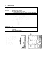
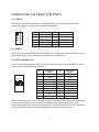
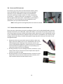
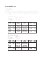
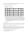
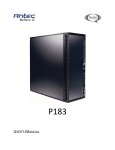
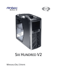
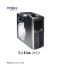
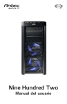
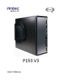
P193 V3
USER’S MANUAL
TABLE OF CONTENTS
INTRODUCTION
1.1
Case Specifications.…..…………………………………………………………………………………..3
1.2
Diagram…………………………………………………………………….…………………………………. 3
HARDWARE INSTALLATION GUIDE
2.1
Setting Up….…………………………………………………………………………………………………. 4
2.2
Power Supply Installation……………………………………………………………………………… 4
2.3
CP Series Power Supply Mount…………………………………………………………………….. 5
2.4
Cable Management………………………………………………………………………………………. 5
2.5
Motherboard Installation..……………………………………………………………………………. 5
2.6
Internal 3.5” Device Installation……………………………………………………………………. 6
2.7
External 3.5” Device Installation…………………………………………………………………… 7
2.8
External 5.25” Device Installation…………………………………………………………………. 7
2.9
Internal 2.5” Device Installation…………………………………………………………………. 8
CONNECTING THE FRONT I/O PORTS
3.1
USB 2.0 Ports………………………………………………….……………………………………………. 9
3.2
USB 3.0 Port………………………………….……………………………………………………………. 9
3.3
AC’97 / HD Audio Ports……………………….…………………………………………………………9
3.4
Switch and LED Connectors……………………………………………………………………………10
3.5
Rewiring Motherboard Header Connections………………………………………………… 10
COOLING SYSTEM
4.1
TriCool™ Fans ………………………………………………………………………………………………. 11
4.2
Optional Fans.………………………………………………………………………………………………. 12
4.3
Washable Air Filters………………………………………..……………………………………………. 13
1
P193 USER’S MANUAL
At Antec, we continually refine and improve our products to ensure the highest quality. It’s possible
that your new case will differ slightly from the descriptions in this manual. As of the date of
publication, all features, descriptions, and illustrations in this manual are correct.
Disclaimer
This manual is intended only as a guide for Antec’s computer enclosures. For more comprehensive
instructions on installing the motherboard and peripherals, please refer to the user’s manuals that
come with those components.
The P193 does not come with a power supply unit (PSU). Make sure you choose a power supply that is
compatible with your computer components and has a long enough power harness to reach your
motherboard and peripheral devices. We recommend our CP Series, TruePower Series or Signature
Series power supplies for the latest ATX specification compliance, broad compatibility, and energysaving capability.
Although care has been taken to prevent sharp edges in your Antec case, we strongly recommend
taking the appropriate time and care when working with it. Avoid hurried or careless motions. Please
use reasonable precaution.
This manual is not designed to cover CPU, RAM, or expansion card installation. Please consult the
motherboard manual for specific mounting instructions and troubleshooting. Before proceeding,
check the manual for your CPU cooler to find out if there are steps you must take before installing the
motherboard. While installing hardware, keep your case on a flat, stable surface.
2
1.1
CASE SPECIFICATIONS
Case Type
Advanced Mid Tower
Color
Gunmetal Gray
20.3" (H) x 8.1" (W) x 23.3" (D)
514 mm (H) x 241 mm (W) x 590 mm (D)
* Actual clearance for width is 9.5” / 241 mm due to the side panel fan
43.2 lbs / 19.6 kg
- 1 x Rear 120 mm TriCool™ exhaust fan
- 2 x Top 140 mm exhaust TriCool™ fan
- 1 x Side 200 mm Big Boy 200™ fan for dual video cards
- 1 x Lower (optional) chamber 120 mm TriCool™ fan
- 1 x Front (optional) 120 mm fan mount for HDD
- 1 x Middle (optional) 120 mm fan mount for video cards
11 Drive Bays:
- 4 x External 5.25” drive bays
- 1 x External 3.5” drive bay
- 6 x Internal 3.5” drive bays
- 2 x Internal 2.5” drive bays
Dimensions
Weight
Cooling
Drive Bays
Expansion Slots
7
Motherboard Size
Mini-ITX, microATX, Standard ATX, Extended ATX
2 x USB 2.0
1 x USB 3.0
AC’97 / HD Audio In and Out
Front I/O Panel
1.2 DIAGRAM
1.
2.
3.
4.
5.
6.
7.
8.
9.
Rear 120 mm TriCool™ fan
Top 140 mm TriCool™ fans
200 mm side Big Boy 200™ fan
Washable air filters
Motherboard mount
Power supply mount
5.25” drive bays
3.5” hard drive bays
Front I/O panel
3
HARDWARE INSTALLATION GUIDE
2.1 SETTING UP
1.
2.
3.
Place the case upright on a flat, stable surface with the
rear of the case facing you.
Remove the thumbscrews from the right side panel.
Grip the panel at the top and bottom and slide it toward
you to open the case.
Remove the screws from the left side panel. Grip the
panel at the top and bottom and slide it toward you to
remove the left side panel.
Note: Do not use your fingernails to pry or lift the
panels.
Inside the case you should see two separate chambers: the upper chamber for the motherboard,
externally accessible drives and hard drives; and the lower chamber for the power supply and hard
drives. You will also find some wiring with marked connectors (USB, PWR, etc.), the installed I/O panel,
a box containing one set each of drive rails for a 5.25” drive and a floppy disk drive, and a tool box
attached to the upper HDD cage containing more hardware (screws, brass standoffs, spare silicone
grommets, etc.).
2.2 POWER SUPPLY INSTALLATION
Most power cables can be routed behind the motherboard through the cable management
compartment. If some cables can’t reach, run them through the passage that goes straight into the
motherboard compartment.
1. Remove both side panels.
2. If you are installing an Antec CP series power supply, you will need to
remove the PSU adapter plate.
3. Slide the power supply into the case. If not routing cables through the
cable management compartment behind the motherboard, route
cables through the covered opening. This will save a few inches of
cable travel and help improve airflow in the power supply
compartment.
Note: Power supplies with fans on the bottom will need to be
mounted so that the fan is facing the top of the case. There are
mounting holes for power supplies to be installed upside up or
upside down.
4. Secure the power supply by fastening it to the back of the case with
the provided screws.
4
2.3 CP SERIES POWER SUPPLY MOUNT
Your Antec P193 enclosure comes with a power supply mounting
adapter to mount either a standard-size power supply or the unique
Antec CP Series high-performance power supply. This adapter is
mounted to the chassis with standard Phillips-head screws. In order to
install the CP Series power supply, remove the mounting plate first.
2.4 CABLE ORGANIZERS
There is a cable management compartment between the motherboard and right side panel. You can
tuck or route excess cables in this compartment.
1.
2.
3.
4.
Remove both side panels.
Choose the cables you would like to pass through the holes behind the motherboard tray and pull
them out of the power supply chamber toward the right side of the case.
Use the cable ties provided to hold them in place.
Feed the cables back through the insertion point nearest the destination of the cable. Connect the
cable and then pull the slack back to the right side of the case.
2.5 MOTHERBOARD INSTALLATION
1.
2.
3.
4.
5.
6.
Lay the case down, with the open side facing up. The
drive cages and power supply should be visible.
Make sure you have the correct I/O panel for your
motherboard. If the panel provided with the case isn’t
suitable, please contact your motherboard
manufacturer for the correct I/O panel.
Align your motherboard with the standoff holes and
remember which holes are lined up. Not all
motherboards will match with all the provided holes;
this is normal and won’t affect its functionality.
Remove your motherboard by lifting it up.
Install standoffs as needed and put the motherboard
back in.
Screw in your motherboard to the standoffs with the
provided Phillips-head screws.
Note: The P183 comes with a CPU cutout on the motherboard tray, which will allow you to change
your CPU heatsink without removing the motherboard.
5
2.6 INTERNAL 3.5” DEVICE INSTALLATION
With the front bezel facing you, swing the front door open. It can swing 270º so the door is parallel with
the side of the case. You can see there are four 5.25” and one 3.5” external drive bays. Inside the case
there are two 3.5” drive cages, which can house up to six hard drives.
Note: We recommend using the lower HDD cage to maximize cooling and quiet computing.
Upper HDD Installation
1. Remove the thumbscrew holding the upper HDD cage.
2. Pull the HDD cage from its position by pulling the ring toward you.
3. There are two HDD trays inside the cage. Squeeze the metal clips on each side of the tray and slide
the tray out.
4. Mount your hard drive into the drive tray with the special screws provided. Don’t over-tighten the
screws as this will reduce the vibration and noise dampening ability of the silicone grommets.
Note: Always mount the HDD with the thicker side of the silicone grommets facing up.
5.
6.
7.
8.
Slide and lock the tray back into the cage.
Slide the cage back into the case and fasten the thumbscrew.
Find the right Molex or SATA connector on the power supply and connect it to the hard drive.
Repeat the same procedure for the other drives.
Lower HDD Installation
1. Remove the thumbscrew holding the lower HDD cage.
2. Pull the HDD cage from its position by pulling the ring towards
you.
3. You can mount up to four hard drives inside the cage. They are
mounted vertically with the silicone grommets sitting at both
sides.
4. Mount your hard drive into the drive cage with the special screws
provided. Don’t over-tighten the screws as this will reduce the
vibration and noise dampening ability of the silicone grommets.
Note: Always mount the HDD with the thicker side of the silicone
grommets facing up.
5.
6.
Slide the cage back into the case and fasten the thumbscrew.
Find a Molex or SATA connector on the power supply and connect
it to the hard drive.
6
2.7 EXTERNAL 3.5” DEVICE INSTALLATION
There is one external 3.5” drive bay.
1.
2.
3.
4.
5.
Carefully remove the plastic drive bay cover and metal plate covering the drive bay.
Find a pair of 3.5”drive rails in the hardware kit box.
Mount the drive rails onto the sides of the 3.5” device. Make sure the metal portion is angled on
the outside and facing forward.
Slide the device into the drive bay until it clicks into place.
Connect a small 4-pin connector from the power supply to the 4-pin connector on the floppy drive.
2.8 EXTERNAL 5.25” DEVICE INSTALLATION
There are four 5.25” drive bays and 8 drive rails.
1.
2.
3.
4.
5.
Carefully remove the plastic drive bay cover / filter and metal
plate covering the drive bay.
Mount the drive rails onto the sides of the 5.25” device. Make
sure the metal portion of the rail faces the front of the drive.
Slide the device into the drive bay until it clicks into place.
Mount the other devices accordingly.
Connect the appropriate Molex or SATA power connector from
the PSU to the power connector on the device.
7
2.9
INTERNAL 2.5” DEVICE INSTALLATION
Your case has two HDD trays in the upper HDD cage that can each support one 2.5” device. Note that
installing a 2.5” device in one of these trays will make it unavailable for 3.5” device use.
1.
2.
3.
4.
5.
5.
6.
7.
8.
Remove the thumbscrew holding the upper HDD cage.
Pop the pull-ring free from its holder. Remove the HDD cage
from its position by pulling the ring toward you.
There are two HDD trays inside the cage. Squeeze the metal
clips on each side of a tray and slide the tray out.
There are four silicone grommets pre-installed on the tray.
Re-configure them for a 2.5” device by moving all 4
grommets to their positions on the inside of the tray.
Mount your hard drive into the drive tray with the special
screws provided.
Note: Always mount the silicone grommets with the thicker
side of the silicone grommets facing up, and place the
hard drive on top. Don’t torque or over-tighten the
screws, as this will reduce the vibration- and noisedampening ability of the silicone grommets.
Slide and lock the tray back into the cage.
Slide the cage back into the case and fasten the
thumbscrew.
Find the right Molex or SATA connector on the power
supply and connect it to the hard drive.
Repeat steps 3-5 for an additional 2.5” drive if applicable.
8
CONNECTING THE FRONT I/O PORTS
3.1 USB 2.0
Connect the front I/O panel USB cable to the USB header pin on your motherboard. Check the
motherboard manual to ensure that it matches the table below:
1
2
Pin
9 10
Signal Names
Pin
Signal Names
1
USB Power 1
2
USB Power 2
3
Negative Signal 1
4
Negative Signal 2
5
Positive Signal 1
6
Positive Signal 2
7
Ground 1
8
Ground 2
9
Key (No Connection)
10
Empty Pin
3.2 USB 3.0
There is a pre-routed cable for the front-panel USB 3.0 port. Plug the back end of this cable into an onboard USB 3.0 port on your motherboard to enable the front USB 3.0 port.
3.3 AC'97 / HD AUDIO PORTS
There is an Intel® standard 10-pin AC’97 connector and an Intel® 10-pin HDA (High Definition Audio)
connector linked to the front panel of the case.
10 6 4 2
9 7 531
Pin
Signal Names
(HDA)
Pin
Signal Names
(AC’97)
1
MIC2 L
1
MIC In
2
AGND
2
GND
3
MIC2 R
3
MIC Power
4
AVCC
4
NC
5
FRO-R
5
Line Out (R)
6
MIC2_JD
6
Line Out (R)
7
F_IO_SEN
7
NC
8
Key (no pin)
8
Key (no pin)
9
FRO-L
9
Line Out (L)
10
LINE2_JD
10
Line Out (L)
You can connect either the AC’97 or the HDA connector, depending on the model of the motherboard.
Locate the internal audio connectors from your motherboard or sound card and connect the
corresponding audio cable. Consult your motherboard or sound card manual for the pin-out positions.
Even if your system supports both audio standards, you may only use one connector.
9
3.4 SWITCH AND LED CONNECTORS
Connected to your front panel are LED and switch leads for power,
reset, and HDD LED activity. Attach these to the corresponding
connectors on your motherboard. Consult your motherboard
manual for specific pin header locations. For LEDs, colored wires
are positive ( + ). White or black wires are negative ( – ). If the LED
does not light up when the system is powered on, try reversing the
connection. For more information on connecting LEDs to your
motherboard, see your motherboard manual.
Note: Polarity (positive and negative) does not matter for switches.
3.5 REWIRING MOTHERBOARD HEADER CONNECTIONS
There may come a time when you need to reconfigure the pin-out of a motherboard header connector.
Examples could be for your USB header, audio input header, or some other front panel connector such
as the Power Button connector. Before performing any work, please refer to your motherboard manual
or your motherboard manufacturer's website to be sure of the pin-out needed for your connector. We
strongly recommend making a notated drawing before beginning work so that you can recover if your
work gets disturbed.
1. Determine which wires you need to remove inorder to rewire your
plug to match the USB pin-outs on your motherboard (refer to your
motherboard manual). Working on one connector at a time, use
a very small flathead screwdriver or similar tool to lift up on the black
tab located beside the gold posts (squares). This will allow you to
easily slide out the pins from the USB plug.
2. Working carefully so as not to damage the wires, connectors, or pins,
slowly remove the pin from the connector. Repeat these steps for
each wire you need to change.
3. Working carefully so as not to damage the wires, connectors or pins,
slowly reinsert the pin into the correct slot of the connector, then
snap closed the black tab that was lifted in Step 1.
10
COOLING SYSTEM
4.1 TRICOOL™ FANS
Rear / Top TriCool™ Fans – There is one rear 120mm and two top 140mm TriCool™ fans pre-installed in
the case. They have external, three-speed switches that let you choose between quiet, performance, or
maximum cooling on each of the fans. The default speed setting is Low. The two fans are mounted so
that the air is exhausting from the case. There are externally accessible switches for these fans located at
the top rear of your case.
120 mm TriCool™ Specifications:
Size:
120 x 25 mm TriCool™ fan
Rated Voltage:
12V
Operating Voltage:
10.2V - 13.8V
Speed
(RPM)
Input
Current
Air Flow
Static
Pressure
Acoustic
Noise
Input
Power
High
2000
0.24A
(Max.)
2.2 m³ / min
(79 CFM)
2.5mm-H2O
(0.10 inch-H2O)
30 dBA
2.9W
Medium
1600
0.20A
1.6 m³ / min
(56 CFM)
1.5mm-H2O
(0.06 inch-H2O)
28 dBA
2.4W
Low
1200
0.13A
1.1 m³ / min
(39 CFM)
0.9mm-H2O
(0.04 inch-H2O)
25 dBA
1.6W
140 mm TriCool™ Specifications:
Size:
140 x 25 mm
Rated Voltage:
DC 12V
Operating Voltage:
10.2V ~ 13.8V
Speed
(RPM)
Input
Current
Air Flow
Static
Pressure
Acoustic
Noise
Input
Power
High
1500
0.28A
(Max.)
2.7 m³ / min
(94.6 CFM)
1.7mm-H2O
(0.07 inch-H2O)
32 dBA
3.4W
Medium
1100
0.20A
1.9 m³ / min
(66.8 CFM)
0.9mm-H2O
(0.04 inch-H2O)
21 dBA
2.4W
Low
700
0.15A
1.33 m³ / min
(47 CFM)
0.4mm-H2O
(0.02 inch-H2O)
20 dBA
1.8W
11
Side Panel TriCool™ Fan – This Big Boy 200™ fan is placed in the side panel of the case, ensuring proper
cooling of the hottest graphics cards and motherboard equipment.
Big Boy 200™ Specifications:
Size:
200 x 30 mm
Rated Voltage:
DC 12V
Operating Voltage:
10.2V ~ 13.8V
Speed
(RPM)
Input
Current
Air Flow
Static
Pressure
Acoustic
Noise
Input
Power
High
800
0.3A
(Max.)
3.8 m³ / min
(134 CFM)
0.7mm-H2O
(0.03 inch-H2O)
29 dBA
3.6W
Medium
600
0.17A
3.1 m³ / min
(108 CFM)
0.4mm-H2O
(0.02 inch-H2O)
27 dBA
2.0W
Low
400
0.08A
2.3 m³ / min
(83 CFM)
0.2mm-H2O
(0.01 inch-H2O)
24 dBA
1.0W
Note: The minimum voltage to start a 120mm TriCool™ fan is 5V. We recommend that you set the
fan speed switch to High if you choose to connect the fan(s) to a fan control device or to the
Fan-Only connector found on some Antec power supplies. A fan control device regulates the
fan speed by varying the voltage, which may start as low as 4.5V to 5V. Connecting a TriCool™
fan set on Medium or Low to a fan-control device may result in the fan not being able to start
because the already lowered voltage from the fan control device will be further reduced by
the TriCool™ circuitry below 5V.
4.2
OPTIONAL FANS
There are three optional 120 mm fan mounts – two front fans and a middle fan (at the rear of the upper
HDD cage). These three fans should be installed so that the air is blowing into the case from the front.
Front Fans – The front fans are designed to enhance the HDD cooling.
Middle Fan – The middle fan is designed to cool the VGA solution in your computer. In this case, the
HDD cage acts as a duct, drawing cool air from the front of the case. You can choose to mount only the
middle fan or you can mount both the front and the middle fan to enhance cooling. If you decide to
mount any HDD into the upper cage you will not be able to use the middle fan.
1.
2.
3.
Find the two fan wire brackets from the hardware kit box.
Install the wire brackets into the HDD cage.
Clip the fan into position.
12
Note: In order to build a quieter system we recommend NOT installing the optional fans if they are
not necessary for the cooling of your components. If you choose to install them, we
recommend using Antec 120mm TriCool™ fans and setting the speed to Low.
4.3 WASHABLE AIR FILTERS
There are two filters located behind the front grills and one behind the grill of the side Big Boy 200™.
Occasionally, it will be necessary to wash the installed air filters, as not washing them may result in
higher system temperatures and possible stability problems. We recommend checking the air filter at
least once a month initially. The frequency will change depending on environmental conditions and
system usage, as users whose systems run 24/7 will likely have to check more often than those who do
not use their systems every day.
To remove the front filters:
1. Push one of the fan grills at the right middle edge to separate the grill from the chassis. The filter
will still be attached by a hinge on the opposite side of the filter. Swing the filter out so that it is
perpendicular to the case.
2. Using both hands, lift the filter up and angle the base of the filter toward you until both tabs detach
from the hinge. Remove the filter.
To remove the side filter:
1. Examine the external fan assembly on the panel and locate the filter tab.
2. Pull on the tab to remove the filter.
13
Antec, Inc.
47900 Fremont Blvd.
Fremont, CA 94538
USA
tel: 510-770-1200
fax: 510-770-1288
Antec Europe B.V.
Stuttgartstraat 12
3047 AS Rotterdam
Netherlands
tel: +31 (0) 10 462-2060
fax: +31 (0) 10 437-1752
Customer Support: US & Canada
1-800-22ANTEC
[email protected]
Europe
+31 (0) 10 462-2060
[email protected]
www.antec.com
© Copyright 2010 Antec, Inc. All rights reserved.
All trademarks are the property of their respective owners. Reproduction in whole or in part
without written permission is prohibited.
14