1
TL-SG2216/TL-SG2424
Gigabit Smart Switch
Rev: 1.0.0
1910010666
COPYRIGHT & TRADEMARKS
Specifications are subject to change without notice.
is a registered trademark of
TP-LINK TECHNOLOGIES CO., LTD. Other brands and product names are trademarks or
registered trademarks of their respective holders.
No part of the specifications may be reproduced in any form or by any means or used to make any
derivative such as translation, transformation, or adaptation without permission from TP-LINK
TECHNOLOGIES CO., LTD. Copyright © 2012 TP-LINK TECHNOLOGIES CO., LTD. All rights
reserved.
http://www.tp-link.com
FCC STATEMENT
This equipment has been tested and found to comply with the limits for a Class A digital device,
pursuant to part 15 of the FCC Rules. These limits are designed to provide reasonable protection
against harmful interference when the equipment is operated in a commercial environment. This
equipment generates, uses, and can radiate radio frequency energy and, if not installed and used
in accordance with the instruction manual, may cause harmful interference to radio
communications. Operation of this equipment in a residential area is likely to cause harmful
interference in which case the user will be required to correct the interference at his own expense.
This device complies with part 15 of the FCC Rules. Operation is subject to the following two
conditions:
1)
This device may not cause harmful interference.
2)
This device must accept any interference received, including interference that may cause
undesired operation.
Any changes or modifications not expressly approved by the party responsible for compliance
could void the user’s authority to operate the equipment.
CE Mark Warning
This is a class A product. In a domestic environment, this product may cause radio interference, in
which case the user may be required to take adequate measures.
SAFETY NOTICES
Caution:
Do not use this product near water, for example, in a wet basement or near a swimming pool.
Avoid using this product during an electrical storm. There may be a remote risk of electric shock
from lightning.
III
Продукт сертифіковано згідно с правилами системи УкрСЕПРО на відповідність вимогам
нормативних документів та вимогам, що передбачені чинними законодавчими актами
України.
IV
CONTENTS
Package Contents ..........................................................................................................................1
Chapter 1 About this Guide...........................................................................................................2
1.1
Intended Readers .........................................................................................................2
1.2
Conventions..................................................................................................................2
1.3
Overview of This Guide ................................................................................................2
Chapter 2 Introduction ..................................................................................................................5
2.1
Overview of the Switch .................................................................................................5
2.2
Main Features...............................................................................................................5
2.3
Appearance Description ...............................................................................................5
2.3.1
Front Panel ........................................................................................................5
2.3.2
Rear Panel .........................................................................................................6
Chapter 3 Login to the Switch.......................................................................................................8
3.1
Login.............................................................................................................................8
3.2
Configuration ................................................................................................................8
Chapter 4 System .......................................................................................................................10
4.1
4.2
4.3
4.4
System Info.................................................................................................................10
4.1.1
System Summary.............................................................................................10
4.1.2
Device Description ...........................................................................................12
4.1.3
System Time ....................................................................................................12
4.1.4
Daylight Saving Time .......................................................................................13
4.1.5
System IP.........................................................................................................14
User Manage ..............................................................................................................15
4.2.1
User Table........................................................................................................15
4.2.2
User Config ......................................................................................................16
System Tools ..............................................................................................................17
4.3.1
Config Restore .................................................................................................17
4.3.2
Config Backup..................................................................................................18
4.3.3
Firmware Upgrade ...........................................................................................18
4.3.4
System Reboot ................................................................................................19
4.3.5
System Reset...................................................................................................19
Access Security ..........................................................................................................20
4.4.1
Access Control.................................................................................................20
Chapter 5 Switching....................................................................................................................22
5.1
Port .............................................................................................................................22
5.1.1
Port Config .......................................................................................................22
5.1.2
Port Mirror ........................................................................................................23
V
5.2
5.3
5.4
5.1.3
Port Security ....................................................................................................25
5.1.4
Port Isolation ....................................................................................................27
LAG ............................................................................................................................28
5.2.1
LAG Table ........................................................................................................28
5.2.2
Static LAG ........................................................................................................29
Traffic Monitor .............................................................................................................30
5.3.1
Traffic Summary...............................................................................................30
5.3.2
Traffic Statistics ................................................................................................32
MAC Address..............................................................................................................33
5.4.1
Address Table ..................................................................................................34
5.4.2
Static Address ..................................................................................................35
5.4.3
Dynamic Address .............................................................................................36
5.4.4
Filtering Address ..............................................................................................38
Chapter 6 VLAN..........................................................................................................................40
6.1
6.2
802.1Q VLAN..............................................................................................................41
6.1.1
VLAN Config ....................................................................................................43
6.1.2
Port Config .......................................................................................................45
Application Example for 802.1Q VLAN .......................................................................47
Chapter 7 Spanning Tree ............................................................................................................49
7.1
STP Config .................................................................................................................54
7.1.1
STP Config.......................................................................................................54
7.1.2
STP Summary..................................................................................................56
7.2
Port Config..................................................................................................................56
7.3
MSTP Instance ...........................................................................................................58
7.4
7.5
7.3.1
Region Config ..................................................................................................58
7.3.2
Instance Config ................................................................................................59
7.3.3
Instance Port Config.........................................................................................60
STP Security...............................................................................................................62
7.4.1
Port Protect ......................................................................................................62
7.4.2
TC Protect........................................................................................................65
Application Example for STP Function .......................................................................65
Chapter 8 Multicast.....................................................................................................................69
8.1
IGMP Snooping ..........................................................................................................71
8.1.1
Snooping Config ..............................................................................................72
8.1.2
Port Config .......................................................................................................73
8.1.3
VLAN Config ....................................................................................................74
8.1.4
Multicast VLAN ................................................................................................76
VI
8.2
8.3
Multicast Filter.............................................................................................................79
8.2.1
IP-Range..........................................................................................................80
8.2.2
Port Filter .........................................................................................................80
Packet Statistics..........................................................................................................82
Chapter 9 QoS............................................................................................................................84
9.1
9.2
DiffServ .......................................................................................................................87
9.1.1
Port Priority ......................................................................................................87
9.1.2
Schedule Mode ................................................................................................88
9.1.3
802.1P Priority .................................................................................................89
9.1.4
DSCP Priority...................................................................................................89
Bandwidth Control ......................................................................................................91
9.2.1
Rate Limit.........................................................................................................91
9.2.2
Storm Control ...................................................................................................92
Chapter 10 SNMP.........................................................................................................................94
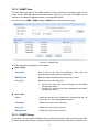
10.1
SNMP Config ..............................................................................................................96
10.1.1
Global Config ...................................................................................................96
10.1.2
SNMP View ......................................................................................................97
10.1.3
SNMP Group....................................................................................................97
10.1.4
SNMP User ......................................................................................................99
10.1.5
SNMP Community..........................................................................................100
10.2
Notification................................................................................................................103
10.3
RMON.......................................................................................................................104
10.3.1
History Control ...............................................................................................105
10.3.2
Event Config ..................................................................................................106
10.3.3
Alarm Config ..................................................................................................106
Chapter 11 Maintenance ............................................................................................................109
11.1
11.2
11.3
System Monitor.........................................................................................................109
11.1.1
CPU Monitor ..................................................................................................109
11.1.2
Memory Monitor ............................................................................................. 110
Log............................................................................................................................ 110
11.2.1
Log Table ....................................................................................................... 111
11.2.2
Local Log ....................................................................................................... 112
11.2.3
Remote Log ................................................................................................... 112
11.2.4
Backup Log .................................................................................................... 113
Device Diagnose....................................................................................................... 114
11.3.1
Cable Test ...................................................................................................... 114
11.3.2
Loopback ....................................................................................................... 115
VII
11.4
Network Diagnose .................................................................................................... 115
11.4.1
Ping................................................................................................................ 115
11.4.2
Tracert............................................................................................................ 116
Appendix A: Specifications ......................................................................................................... 118
Appendix B: Configuring the PCs ............................................................................................... 119
Appendix C: Glossary.................................................................................................................121
VIII
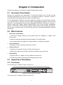
Package Contents
The following items should be found in your box:
One Gigabit Smart Switch
One power cord
Two mounting brackets and other fittings
Installation Guide
Resource CD for TL-SG2216/TL-SG2424 Switch, including:
This User Guide
Other Helpful Information
Note:
Make sure that the package contains the above items. If any of the listed items are damaged or
missing, please contact with your distributor.
1
Chapter 1 About this Guide
This User Guide contains information for setup and management of TL-SG2216/TL-SG2424
Gigabit Smart Switch. Please read this guide carefully before operation.
1.1 Intended Readers
This Guide is intended for network managers familiar with IT concepts and network terminologies.
1.2 Conventions
In this Guide the following conventions are used:
The
switch
or
TL-SG2216/TL-SG2424
mentioned
in
this
Guide
stands
for
TL-SG2216/TL-SG2424 Gigabit Smart Switch without any explanation.
Tips:
The two devices of TL-SG2216 and TL-SG2424 are sharing this User Guide. For simplicity, we will
take TL-SG2216 for example throughout the configuration chapters. TL-SG2216 and TL-SG2424
just differ in the number of LED indicators and ports and all figures in this guide are of TL-SG2216.
Menu Name→Submenu Name→Tab page indicates the menu structure. System→System
Info→System Summary means the System Summary page under the System Info menu
option that is located under the System menu.
Bold font indicates a button, a toolbar icon, menu or menu item.
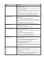
Symbols in this Guide:
Symbol
Description
Note:
Ignoring this type of note might result in a malfunction or damage to the device.
Tips:
This format indicates important information that helps you make better use of your
device.
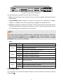
1.3 Overview of This Guide
Chapter
Introduction
Chapter 1 About This Guide
Introduces the guide structure and conventions.
Chapter 2 Introduction
Introduces the features, application
TL-SG2216/TL-SG2424 switch.
Chapter 3 Login to the Switch
Introduces how to log on to the Web management page.
2
and
appearance
of
Chapter
Introduction
Chapter 4 System
This module is used to configure system properties of the switch.
Here mainly introduces:
System Info: Configure the description, system time and network
parameters of the switch.
User Manage: Configure the user name and password for users
to log on to the Web management page with a certain access
level.
System Tools: Manage the configuration file of the switch.
Access Security: Provide different security measures for the
login to enhance the configuration management security.
Chapter 5 Switching
This module is used to configure basic functions of the switch. Here
mainly introduces:
Port: Configure the basic features for the port.
LAG: Configure Link Aggregation Group. LAG is to combine a
number of ports together to make a single high-bandwidth data
path.
Traffic Monitor: Monitor the traffic of each port
MAC Address: Configure the address table of the switch.
Chapter 6 VLAN
This module is used to configure VLANs to control broadcast in
LANs. Here mainly introduces:
802.1Q VLAN: Configure port-based VLAN.
Chapter 7 Spanning Tree
This module is used to configure spanning tree function of the
switch. Here mainly introduces:
STP Config: Configure and view the global settings of spanning
tree function.
Port Config: Configure CIST parameters of ports.
MSTP Instance: Configure MSTP instances.
STP Security: Configure protection function to prevent devices
from any malicious attack against STP features.
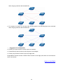
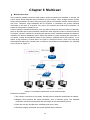
Chapter 8 Multicast
This module is used to configure multicast function of the switch.
Here mainly introduces:
IGMP Snooping: Configure global parameters of IGMP Snooping
function, port properties, VLAN and multicast VLAN.
Multicast IP: Configure multicast IP table.
Multicast Filter: Configure multicast filter feature to restrict users
ordering multicast programs.
Packet Statistics: View the multicast data traffic on each port of
the switch, which facilitates you to monitor the IGMP messages
in the network.
Chapter 9 QoS
This module is used to configure QoS function to provide different
quality of service for various network applications and
requirements. Here mainly introduces:
DiffServ: Configure priorities, port priority, 802.1P priority and
DSCP priority.
Bandwidth Control: Configure rate limit feature to control the
traffic rate on each port; configure storm control feature to filter
broadcast, multicast and UL frame in the network.
3
Chapter
Introduction
Chapter 10 SNMP
This module is used to configure SNMP function to provide a
management frame to monitor and maintain the network devices.
Here mainly introduces:
SNMP Config: Configure global settings of SNMP function.
Notification: Configure notification function for the management
station to monitor and process the events.
RMON: Configure RMON function to monitor network more
efficiently.
Chapter 11 Maintenance
This module is used to assemble the commonly used system tools
to manage the switch. Here mainly introduces:
System Monitor: Monitor the memory and CPU of the switch.
Log: View configuration parameters on the switch.
Device Diagnose: Test the connection status of the cable
connected to the switch, test if the port of the switch and the
connected device are available.
Network Diagnose: Test if the destination is reachable and the
account of router hops from the switch to the destination.
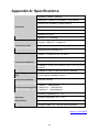
Appendix A Specifications
Lists the hardware specifications of the Switch.
Appendix B Configure the PCs
Introduces how to configure the PCs.
Appendix C Glossary
Lists the glossary used in this manual.
Return to CONTENTS
4
Chapter 2 Introduction
Thanks for choosing the TL-SG2216/TL-SG2424 Gigabit Smart Switch!
2.1 Overview of the Switch
Designed for workgroups and departments, TL-SG2216/TL-SG2424 from TP-LINK provides
wire-speed performance and full set of layer 2 management features. It provides a variety of
service features and multiple powerful functions with high security.
The EIA-standardized framework and smart configuration capacity can provide flexible solutions
for a variable scale of networks. QoS and IGMP snooping/filtering optimize voice and video
application. Link aggregation (LACP) increase aggregated bandwidth, optimizing the transport of
business critical data. SNMP, RMON, WEB/CLI/Telnet Log-in bring abundant management
policies. TL-SG2216/TL-SG2424 Switch integrates multiple functions with excellent performance,
and is friendly to manage, which can fully meet the need of the users demanding higher networking
performance.
2.2 Main Features
Resiliency and Availability
+ IEEE 802.1s Multiple Spanning Tree provides high link availability in multiple VLAN
environments.
+ Multicast snooping automatically prevents flooding of IP multicast traffic.
+ Root Guard protects root bridge from malicious attack or configuration mistakes
Layer 2 Switching
+ Supports 512 active VLAN groups and 4K VLAN IDs.
Quality of Service
+ Supports L2/L3 granular CoS with 4 priority queues per port.
+ Rate limiting confines the traffic flow accurately according to the preset value.
Manageability
+ Supports Telnet, CLI, SNMP v1/v2c/v3, RMON and web access.
+ Port Mirroring enables monitoring selected ingress/egress traffic.
2.3 Appearance Description
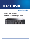
2.3.1 Front Panel
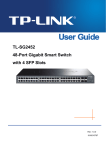
The front panel of TL-SG2216 is shown as Figure 2-1.
Figure 2-1 Front Panel of TL-SG2216
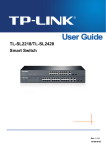
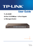
The front panel of TL-SG2424 is shown as Figure 2-2.
5
Figure 2-2 Front Panel of TL-SG2424
The following parts are located on the front panel of the Switch:
Reset: Press this button for five seconds or above to reset the software setting back to factory
default setting.
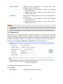
10/100/1000Mbps Ports: Designed to connect to the device with a bandwidth of 10Mbps,
100Mbps or 1000Mbps. Each has a corresponding 1000Mbps LED and link/Act LED.
SFP Ports: Designed to install the SFP module. The SFP ports share the same LEDs with the
corresponding RJ45 ports, and they are referred to as “combo” ports, which means they cannot
be used simultaneously, otherwise only SFP ports work.
Note:
When using the SFP port with a 100Mbps module or a gigabit module, you need to configure its
corresponding Speed and Duplex mode on Switching→Port→Port Config page. For 100M
module, please select 100MFD while select 1000MFD for gigabit module. By default, the Speed
and Duplex mode of SFP port is 1000MFD.
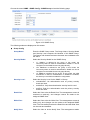
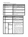
LEDs
Name
Status
On
Power
System
1000Mbps
Link/Act
Flashing
Indication
Power is on.
Power supply is abnormal.
Off
Power is off or power supply is abnormal.
On
The Switch is working abnormally.
Flashing
The Switch is working normally.
Off
The Switch is working abnormally.
On
A 1000Mbps device is connected to the corresponding port.
Off
A 10/100Mbps device or no device is connected to the
corresponding port.
On
A device is connected to the corresponding port but no activity.
Flashing
Off
Data is being transmitted or received.
No device is connected to the corresponding port.
2.3.2 Rear Panel
The rear panel of TL-SG2216/TL-SG2424 features a power socket and a Grounding Terminal
(marked with ).
6
Figure 2-3 Rear Panel of TL-SG2216
Figure 2-4 Rear Panel of TL-SG2424
Grounding Terminal: TL-SG2216/TL-SG2424 already comes with Lightning Protection
Mechanism. You can also ground the Switch through the PE (Protecting Earth) cable of AC
cord or with Ground Cable.
AC Power Socket: Connect the female connector of the power cord here, and the male
connector to the AC power outlet. Please make sure the voltage of the power supply meets the
requirement of the input voltage (100-240V~ 50/60Hz 0.6A).
Return to CONTENTS
7
Chapter 3 Login to the Switch
3.1 Login
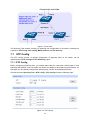
1) To access the configuration utility, open a web-browser and type in the default address
http://192.168.0.1 in the address field of the browser, then press the Enter key.
Figure 3-1 Web-browser
Tips:
To log in to the Switch, the IP address of your PC should be set in the same subnet addresses of
the Switch. The IP address is 192.168.0.x ("x" is any number from 2 to 254), Subnet Mask is
255.255.255.0. For the detailed instructions as to how to do this, please refer to Appendix B.
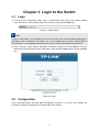
2) After a moment, a login window will appear, as shown in Figure 3-2. Enter admin for the User
Name and Password, both in lower case letters. Then click the Login button or press the Enter
key.
Figure 3-2 Login
3.2 Configuration
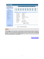
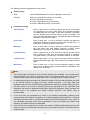
After a successful login, the main page will appear as Figure 3-3, and you can configure the
function by clicking the setup menu on the left side of the screen.
8
Figure 3-3 Main Setup-Menu
Note:
Clicking Apply can only make the new configurations effective before the switch is rebooted. If
you want to keep the configurations effective even the switch is rebooted, please click Saving
Config. You are suggested to click Saving Config before cutting off the power or rebooting the
switch to avoid losing the new configurations.
Return to CONTENTS
9
Chapter 4 System
The System module is mainly for system configuration of the switch, including four submenus:
System Info, User Manage, System Tools and Access Security.
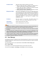
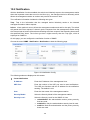
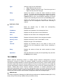
4.1 System Info
The System Info, mainly for basic properties configuration, can be implemented on System
Summary, Device Description, System Time, Daylight Saving Time and System IP pages.
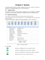
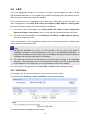
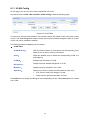
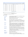
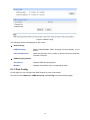
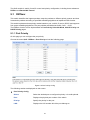
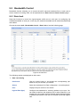
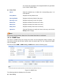
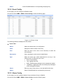
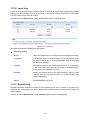
4.1.1 System Summary
On this page you can view the port connection status and the system information.
The port status diagram shows the working status of 16 10/100/1000Mbps RJ45 ports and 2 SFP
ports of the switch.
Choose the menu System→System Info→System Summary to load the following page.
Figure 4-1 System Summary
Port Status
Indicates the 1000Mbps port is not connected to a device.
Indicates the 1000Mbps port is at the speed of 1000Mbps.
Indicates the 1000Mbps port is at the speed of 10Mbps or 100Mbps.
Indicates the SFP port is not connected to a device.
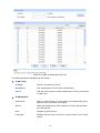
10
Indicates the SFP port is at the speed of 1000Mbps.
Indicates the SFP port is at the speed of 100Mbps.
When the cursor moves on the port, the detailed information of the port will be displayed.
Figure 4-2 Port Information
Port Info
Port:
Displays the port number of the switch.
Type:
Displays the type of the port.
Rate:
Displays the maximum transmission rate of the port.
Status:
Displays the connection status of the port.
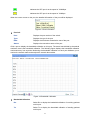
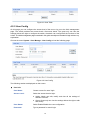
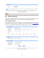
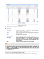
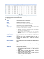
Click a port to display the bandwidth utilization on this port. The actual rate divided by theoretical
maximum rate is the bandwidth utilization. The following figure displays the bandwidth utilization
monitored every four seconds. Monitoring the bandwidth utilization on each port facilitates you to
monitor the network traffic and analyze the network abnormities.
Figure 4-3 Bandwidth Utilization
Bandwidth Utilization
Rx:
Select Rx to display the bandwidth utilization of receiving packets
on this port.
Tx:
Select Tx to display the bandwidth utilization of sending packets
on this port.
11
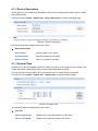
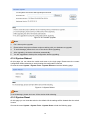
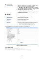
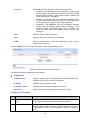
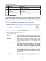
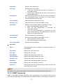
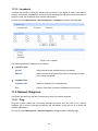
4.1.2 Device Description
On this page you can configure the description of the switch, including device name, device location
and system contact.
Choose the menu System→System Info→Device Description to load the following page.
Figure 4-4 Device Description
The following entries are displayed on this screen:
Device Description
Device Name:
Enter the name of the switch.
Device Location:
Enter the location of the switch.
System Contact:
Enter your contact information.
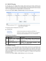
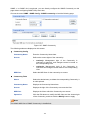
4.1.3 System Time
System Time is the time displayed while the switch is running. On this page you can configure the
system time and the settings here will be used for other time-based functions.
You can manually set the system time or synchronize with PC’s clock as the system time.
Choose the menu System→System Info→System Time to load the following page.
Figure 4-5 System Time
The following entries are displayed on this screen:
Time Info
Current System Date:
Displays the current date and time of the switch.
Current Time Mode:
Displays the current time mode of the switch.
12
Time Config
Manual:
Synchronize
PC’S Clock:
When this option is selected, you can set the date and time
manually.
with
When this option is selected, the administrator PC’s clock is
utilized.
Note:
The system time will be restored to the default when the switch is restarted and you need
reconfigure the system time of the switch.
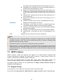
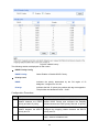
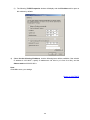
4.1.4 Daylight Saving Time
Here you can configure the Daylight Saving Time of the Switch.
Choose the menu System→System Info→Daylight Saving Time to load the following page.
Figure 4-6 Daylight Saving Time
The following entries are displayed on this screen:
DST Config
DST Status:
Enable or disable the DST.
Predefined Mode:
Select a predefined DST configuration.
USA: First Sunday in April, 02:00 ~ Last Sunday in October,
02:00.
Australia: First Sunday in October, 02:00 ~ First Sunday in
April, 03:00.
European: Last Sunday in March, 01:00 ~ Last Sunday in
October, 01:00.
New Zealand: First Sunday in October, 02:00 ~ Last Sunday
in March, 03:00.
13
Recurring Mode:
Specify the DST configuration
configuration is recurring in use.
Date Mode:
in
recurring
mode.
This
Offset: Specify the time adding in minutes when Daylight
Saving Time comes.
Start/End Time: Select starting time and ending time of
Daylight Saving Time.
Specify the DST configuration in Date mode. This configuration is
one-off in use.
Offset: Specify the time adding in minutes when Daylight
Saving Time comes.
Start/End Time: Select starting time and ending time of
Daylight Saving Time.
Note:
1.
When disable the DST, the predefined mode, recurring mode and date mode cannot be
configured.
2.
When enable the DST, the default daylight saving time is of European in predefined mode.
4.1.5 System IP
Each device in the network possesses a unique IP Address. You can log on to the Web
management page to operate the switch using this IP Address. The switch supports three modes
to obtain an IP address: Static IP, DHCP and BOOTP. The IP address obtained using a new mode
will replace the original IP address. On this page you can configure the system IP of the switch.
Choose the menu System→System Info→System IP to load the following page.
Figure 4-7 System IP
The following entries are displayed on this screen:
IP Config
MAC Address:
Displays MAC Address of the switch.
14
IP Address Mode:
Select the mode to obtain IP Address for the switch.
Static IP: When this option is selected, you should enter IP
Address, Subnet Mask and Default Gateway manually.
DHCP: When this option is selected, the switch will obtain
network parameters from the DHCP Server.
BOOTP: When this option is selected, the switch will obtain
network parameters from the BOOTP Server.
Management VLAN:
Enter the ID of management VLAN, the only VLAN through which
you can get access to the switch. By default VLAN1 owning all the
ports is the Management VLAN and you can access the switch via
any port on the switch. However, if another VLAN is created and
set to be the Management VLAN, you may have to reconnect the
management station to a port that is a member of the
Management VLAN.
IP Address:
Enter the system IP of the switch. The default system IP is
192.168.0.1 and you can change it appropriate to your needs.
Subnet Mask:
Enter the subnet mask of the switch.
Default Gateway:
Enter the default gateway of the switch.
Note:
1. Changing the IP address to a different IP segment will interrupt the network communication, so
please keep the new IP address in the same IP segment with the local network.
2. The switch only possesses an IP address. The IP address configured will replace the original
IP address.
3.
If the switch gets the IP address from DHCP server, you can see the configuration of the
switch in the DHCP server; if DHCP option is selected but no DHCP server exists in the
network, a few minutes later, the switch will restore the setting to the default.
4.
If DHCP or BOOTP option is selected, the switch will gets network parameters dynamically
from the Internet, so IP address, subnet mask and default gateway can not be configured.
5.
By default, the default IP address is 192.168.0.1.
4.2 User Manage
User Manage functions to configure the user name and password for users to log on to the Web
management page with a certain access level so as to protect the settings of the switch from being
randomly changed.
The User Manage function can be implemented on User Table and User Config pages.
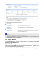
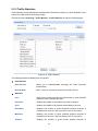
4.2.1 User Table
On this page you can view the information about the current users of the switch.
Choose the menu System→User Manage→User Table to load the following page.
15
Figure 4-8 User Table
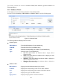
4.2.2 User Config
On this page you can configure the access level of the user to log on to the Web management
page. The switch provides two access levels: Guest and Admin. The guest only can view the
settings without the right to configure the switch; the admin can configure all the functions of the
switch. The Web management pages contained in this guide are subject to the admin’s login without any
explanation.
Choose the menu System→User Manage→User Config to load the following page.
Figure 4-9 User Config
The following entries are displayed on this screen:
User Info
User Name:
Create a name for users’ login.
Access Level:
Select the access level to login.
Admin: Admin can edit, modify and view all the settings of
different functions.
Guest: Guest only can view the settings without the right to edit
and modify.
User Status:
Select Enable/Disable the user configuration.
Password:
Type a password for users’ login.
16
Confirm Password:
Retype the password.
User Table
Select:
Select the desired entry to delete the corresponding user
information. It is multi-optional The current user information can’t
be deleted.
User
ID,
Name,
Access Level and
status:
Displays the current user ID, user name, access level and user
status.
Operation:
Click the Edit button of the desired entry, and you can edit the
corresponding user information. After modifying the settings,
please click the Modify button to make the modification effective.
Access level and user status of the current user information can’t
be modified.
4.3 System Tools
The System Tools function, allowing you to manage the configuration file of the switch, can be
implemented on Config Restore, Config Backup, Firmware Upgrade, System Reboot and
System Reset pages.
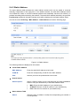
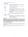
4.3.1 Config Restore
On this page you can upload a backup configuration file to restore your switch to this previous
configuration.
Choose the menu System→System Tools→Config Restore to load the following page.
Figure 4-10 Config Restore
The following entries are displayed on this screen:
Config Restore
Restore Config:
Click the Restore Config button to restore the backup
configuration file. It will take effect after the switch automatically
reboots.
17
Note:
1.
It will take a few minutes to restore the configuration. Please wait without any operation.
2.
To avoid any damage, please don’t power down the switch while being restored.
3.
After being restored, the current settings of the switch will be lost. Wrong uploaded
configuration file may cause the switch unmanaged.
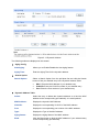
4.3.2 Config Backup
On this page you can download the current configuration and save it as a file to your computer for
your future configuration restore.
Choose the menu System→System Tools→Config Backup to load the following page.
Figure 4-11 Config Backup
The following entries are displayed on this screen:
Config Backup
Backup Config:
Click the Backup Config button to save the current configuration
as a file to your computer. You are suggested to take this measure
before upgrading.
Note:
It will take a few minutes to backup the configuration. Please wait without any operation.
4.3.3 Firmware Upgrade
The switch system can be upgraded via the Web management page. To upgrade the system is to
get more functions and better performance. Go to http://www.tp-link.com to download the updated
firmware.
Choose the menu System→System Tools→Firmware Upgrade to load the following page.
18
Figure 4-12 Firmware Upgrade
Note:
1.
Don’t interrupt the upgrade.
2.
Please select the proper software version matching with your hardware to upgrade.
3.
To avoid damage, please don't turn off the device while upgrading.
4.
After upgrading, the device will reboot automatically.
5.
You are suggested to backup the configuration before upgrading.
4.3.4 System Reboot
On this page you can reboot the switch and return to the login page. Please save the current
configuration before rebooting to avoid loosing the configuration unsaved
Choose the menu System→System Tools→System Reboot to load the following page.
Figure 4-13 System Reboot
Note:
To avoid damage, please don't turn off the device while rebooting.
4.3.5 System Reset
On this page you can reset the switch to the default. All the settings will be cleared after the switch
is reset.
Choose the menu System→System Tools→System Reset to load the following page.
19
Figure 4-14 System Reset
Note:
After the system is reset, the switch will be reset to the default and all the settings will be cleared.
4.4 Access Security
Access Security provides different security measures for the remote login so as to enhance the
configuration management security. It can be implemented on Access Control page.
4.4.1 Access Control
On this page you can control the users logging on to the Web management page to enhance the
configuration management security. The definitions of Admin and Guest refer to 4.2 User Manage.
Choose the menu System→Access Security→Access Control to load the following page.
Figure 4-15 Access Control
20
The following entries are displayed on this screen:
Access Control Config
Control Mode:
Select the control mode for users to log on to the Web
management page.
IP Address&Mask
These fields can be available for configuration only when IP-based
mode is selected. Only the users within the IP-range you set here
are allowed for login.
MAC Address:
The field can be available for configuration only when MAC-based
mode is selected. Only the user with this MAC Address you set
here are allowed for login.
Port:
The field can be available for configuration only when Port-based
mode is selected. Only the users connected to these ports you set
here are allowed for login.
Session Config
Session Timeout:
IP-based: Select this option to limit the IP-range of the users for
login.
MAC-based: Select this option to limit the MAC Address of the
users for login.
Port-based: Select this option to limit the ports for login.
If you do nothing with the Web management page within the
timeout time, the system will log out automatically. If you want to
reconfigure, please login again.
Access User Number
Number Control;
Select Enable/Disable the Number Control function.
Admin Number:
Enter the maximum number of the users logging on to the Web
management page as Admin.
Guest Number:
Enter the maximum number of the users logging on to the Web
management page as Guest.
Return to CONTENTS
21
Chapter 5 Switching
Switching module is used to configure the basic functions of the switch, including four submenus:
Port, LAG, Traffic Monitor and MAC Address.
5.1 Port
The Port function, allowing you to configure the basic features for the port, is implemented on the
Port Config, Port Mirror, Port Security and Port Isolation pages.
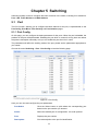
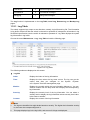
5.1.1 Port Config
On this page, you can configure the basic parameters for the ports. When the port is disabled, the
packets on the port will be discarded. Disabling the port which is vacant for a long time can reduce
the power consumption effectively. And you can enable the port when it is in need.
The parameters will affect the working mode of the port, please set the parameters appropriate to
your needs.
Choose the menu Switching→Port→Port Config to load the following page.
Figure 5-1 Port Config
Here you can view and configure the port parameters.
Port Select:
Click the Select button to quick-select the corresponding port
based on the port number you entered.
Select:
Select the desired port for configuration. It is multi-optional.
Port:
Displays the port number.
Description:
Give a description to the port for identification.
22
Status:
Allows you to Enable/Disable the port. When Enable is selected,
the port can forward the packets normally.
Speed and Duplex:
Select the Speed and Duplex mode for the port. The device
connected to the switch should be in the same Speed and
Duplex mode with the switch. When “Auto” is selected, the
Speed and Duplex mode will be determined by auto-negotiation.
For the SFP port, this Switch does not support auto-negotiation.
Flow Control:
Allows you to Enable/Disable the Flow Control feature. When
Flow Control is enabled, the switch can synchronize the speed
with its peer to avoid the packet loss caused by congestion.
LAG:
Displays the LAG number which the port belongs to.
Note:
1.
The switch can not be managed through the disabled port. Please enable the port which is
used to manage the switch.
2.
The parameters of the port members in a LAG should be set as the same.
3.
When using the SFP port with a 100M module or a gigabit module, you need to configure its
corresponding Speed and Duplex mode. For 100M module, please select 100MFD while
select 1000MFD for gigabit module. By default, the Speed and Duplex mode of SFP port is
1000MFD.
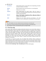
5.1.2 Port Mirror
Port Mirror, the packets obtaining technology, functions to forward copies of packets from
one/multiple ports (mirrored port) to a specific port (mirroring port). Usually, the mirroring port is
connected to a data diagnose device, which is used to analyze the mirrored packets for monitoring
and troubleshooting the network.
Choose the menu Switching→Port→Port Mirror to load the following page.
Figure 5-2 Mirroring Port
23
The following entries are displayed on this screen.
Mirror Group List
Group:
Displays the mirror group number.
Mirroring:
Displays the mirroring port number.
Mode:
Displays the mirror mode. The value will be "Ingress" or "Egress".
Mirrored Port:
Displays the mirrored ports.
Operation:
Click Edit to configure the mirror group.
Click Edit to display the following figure.
Figure 5-3 Mirroring Port
The following entries are displayed on this screen.
Mirror Group
Number:
Select the mirror group number you want to configure.
Mirroring Port
Mirroring Port:
Select the mirroring port number.
24
Mirrored Port
Port Select:
Click the Select button to quick-select the corresponding port based
on the port number you entered.
Select:
Select the desired port as a mirrored port. It is multi-optional.
Port:
Displays the port number.
Ingress:
Select Enable/Disable the Ingress feature. When the Ingress is
enabled, the incoming packets received by the mirrored port will be
copied to the mirroring port.
Egress:
Select Enable/Disable the Egress feature. When the Egress is
enabled, the outgoing packets sent by the mirrored port will be
copied to the mirroring port.
LAG:
Displays the LAG number which the port belongs to. The LAG
member can not be selected as the mirrored port or mirroring port.
Note:
1.
The LAG member can not be selected as the mirrored port or mirroring port.
2.
A port can not be set as the mirrored port and the mirroring port simultaneously.
3.
The Port Mirror function can take effect span the multiple VLANs.
5.1.3 Port Security
MAC Address Table maintains the mapping relationship between the port and the MAC address of
the connected device, which is the base of the packet forwarding. The capacity of MAC Address
Table is fixed. MAC Address Attack is the attack method that the attacker takes to obtain the
network information illegally. The attacker uses tools to generate the cheating MAC address and
quickly occupy the MAC Address Table. When the MAC Address Table is full, the switch will
broadcast the packets to all the ports. At this moment, the attacker can obtain the network
information via various sniffers and attacks. When the MAC Address Table is full, the packets
traffic will flood to all the ports, which results in overload, lower speed, packets drop and even
breakdown of the system.
Port Security is to protect the switch from the malicious MAC Address Attack by limiting the
maximum number of MAC addresses that can be learned on the port. The port with Port Security
feature enabled will learn the MAC address dynamically. When the learned MAC address number
reaches the maximum, the port will stop learning. Thereafter, the other devices with the MAC
address unlearned can not access to the network via this port.
Choose the menu Switching→Port→Port Security to load the following page.
25
Figure 5-4 Port Security
The following entries are displayed on this screen:
Port Security
Select:
Select the desired port for Port Security configuration. It is
multi-optional.
Port:
Displays the port number.
Max Learned MAC:
Specify the maximum number of MAC addresses that can be
learned on the port.
Learned Num:
Displays the number of MAC addresses that have been learned
on the port.
Learn Mode:
Select the Learn Mode for the port.
Status:
Dynamic: When Dynamic mode is selected, the learned
MAC address will be deleted automatically after the aging
time.
Static: When Static mode is selected, the learned MAC
address will be out of the influence of the aging time and
can only be deleted manually. The learned entries will be
cleared after the switch is rebooted.
Permanent: When Permanent mode is selected, the
learned MAC address will be out of the influence of the
aging time and can only be deleted manually. The learned
entries will be saved even the switch is rebooted.
Select Enable/Disable the Port Security feature for the port.
26
Note:
The Port Security function is disabled for the LAG port member. Only the port is removed from the
LAG, will the Port Security function be available for the port.
5.1.4 Port Isolation
Port Isolation provides a method of restricting traffic flow to improve the network security by
forbidding the port to forward packets to the ports that are not on its forward portlist.
Choose the menu “Switching→Port→Port Isolation” to load the following page.
Figure 5-5 Port Isolation
The following entries are displayed on this screen:
Port Isolation Config
Port:
Select the port number to set its forwardlist.
Forward Portlist:
Select the port that to be forwarded to.
Port Isolation List
Port:
Display the port number.
Forward Portlist:
Display the forwardlist.
27
5.2 LAG
LAG (Link Aggregation Group) is to combine a number of ports together to make a single
high-bandwidth data path, so as to implement the traffic load sharing among the member ports in
the group and to enhance the connection reliability.
For the member ports in an aggregation group, their basic configuration must be the same. The
basic configuration includes STP, QoS, VLAN, port attributes, MAC Address Learning mode
and other associated settings. The further explains are following:
If the ports, which are enabled for the 802.1Q VLAN, STP, QoS and Port Configuration
(Speed and Duplex, Flow Control), are in a LAG, their configurations should be the same.
The ports, which are enabled for the Port Security, Port Mirror and MAC Address Filtering,
can not be added to the LAG.
If the LAG is needed, you are suggested to configure the LAG function here before configuring the
other functions for the member ports.
Tips:
1.
Calculate the bandwidth for a LAG: If a LAG consists of the four ports in the speed of
1000Mbps Full Duplex, the whole bandwidth of the LAG is up to 8000Mbps (2000Mbps * 4)
because the bandwidth of each member port is 2000Mbps counting the up-linked speed of
1000Mbps and the down-linked speed of 1000Mbps.
2.
The traffic load of the LAG will be balanced among the ports according to the Aggregate
Arithmetic. If the connections of one or several ports are broken, the traffic of these ports will
be transmitted on the normal ports, so as to guarantee the connection reliability.
The LAG function is implemented on the LAG Table and Static LAG configuration pages.
5.2.1 LAG Table
On this page, you can view the information of the current LAG of the switch.
Choose the menu Switching→LAG→LAG Table to load the following page.
Figure 5-6 LAG Table
The following entries are displayed on this screen:
28
Global Config
Hash Algorithm:
Select the applied scope of Aggregate Arithmetic, which
results in choosing a port to transfer the packets.
SRC MAC + DST MAC: When this option is selected,
the Aggregate Arithmetic will apply to the source and
destination MAC addresses of the packets.
SRC IP + DST IP: When this option is selected, the
Aggregate Arithmetic will apply to the source and destination
IP addresses of the packets.
LAG Table
Select:
Select the desired LAG. It is multi-optional.
Group Number:
Displays the LAG number here.
Description:
Displays the description of LAG.
Member:
Displays the LAG member.
Operation:
Allows you to view or modify the information for each LAG.
Edit: Click to modify the settings of the LAG.
Detail: Click to get the information of the LAG.
Click the Detail button for the detailed information of your selected LAG.
Figure 5-7 Detailed Information
5.2.2 Static LAG
On this page, you can manually configure the LAG.
Choose the menu Switching→LAG→Static LAG to load the following page.
29
Figure 5-8 Manually Config
The following entries are displayed on this screen:
LAG Config
Group Number:
Select a Group Number for the LAG.
Description:
Give a description to the LAG for identification.
Member Port
Member Port:
Select the port as the LAG member. Clearing all the ports of
the LAG will delete this LAG.
Tips:
1.
The LAG can be deleted by clearing its all member ports.
2.
A port can only be added to a LAG. If a port is the member of a LAG, the port number will be
displayed in gray and can not be selected.
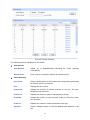
5.3 Traffic Monitor
The Traffic Monitor function, monitoring the traffic of each port, is implemented on the Traffic
Summary and Traffic Statistics pages.
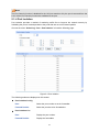
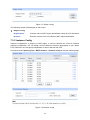
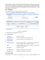
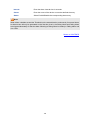
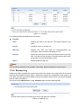
5.3.1 Traffic Summary
Traffic Summary screen displays the traffic information of each port, which facilitates you to
monitor the traffic and analyze the network abnormity.
Choose the menu Switching→Traffic Monitor→Traffic Summary to load the following page.
30
Figure 5-9 Traffic Summary
The following entries are displayed on this screen:
Auto Refresh
Auto Refresh:
Allows you to Enable/Disable refreshing the Traffic Summary
automatically.
Refresh Rate:
Enter a value in seconds to specify the refresh interval.
Traffic Summary
Port Select:
Click the Select button to quick-select the corresponding port based
on the port number you entered.
Port:
Displays the port number.
Packets Rx:
Displays the number of packets received on the port. The error
packets are not counted in.
Packets Tx:
Displays the number of packets transmitted on the port.
Octets Rx:
Displays the number of octets received on the port. The error octets
are counted in.
Octets Tx:
Displays the number of octets transmitted on the port.
Statistics:
Click the Statistics button to view the detailed traffic statistics of the
port.
31
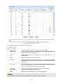
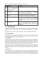
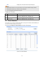
5.3.2 Traffic Statistics
Traffic Statistics screen displays the detailed traffic information of each port, which facilitates you to
monitor the traffic and locate faults promptly.
Choose the menu Switching→Traffic Monitor→Traffic Statistics to load the following page.
Figure 5-10 Traffic Statistics
The following entries are displayed on this screen:
Auto Refresh
Auto Refresh:
Allows you to Enable/Disable refreshing the Traffic Summary
automatically.
Refresh Rate:
Enter a value in seconds to specify the refresh interval.
Statistics
Port:
Enter a port number and click the Select button to view the traffic
statistics of the corresponding port.
Received:
Displays the details of the packets received on the port.
Sent:
Displays the details of the packets transmitted on the port.
Broadcast:
Displays the number of good broadcast packets received or
transmitted on the port. The error frames are not counted in.
Multicast:
Displays the number of good multicast packets received or
transmitted on the port. The error frames are not counted in.
Unicast:
Displays the number of good unicast packets received or
32
transmitted on the port. The error frames are not counted in.
Alignment Errors:
Displays the number of the received packets that have a bad
Frame Check Sequence (FCS) with a non-integral octet
(Alignment Error). The length of the packet is between 64 bytes
and 1518 bytes.
UndersizePkts:
Displays the number of the received packets (excluding error
packets) that are less than 64 bytes long.
Pkts64Octets:
Displays the number of the received packets (including error
packets) that are 64 bytes long.
Pkts65to127Octets:
Displays the number of the received packets (including error
packets) that are between 65 and 127 bytes long.
Pkts128to255Octets:
Displays the number of the received packets (including error
packets) that are between 128 and 255 bytes long.
Pkts256to511Octets:
Displays the number of the received packets (including error
packets) that are between 256 and 511 bytes long.
Pkts512to1023Octets:
Displays the number of the received packets (including error
packets) that are between 512 and 1023 bytes long.
PktsOver1023Octets:
Displays the number of the received packets (including error
packets) that are over 1023 bytes.
Collisions:
Displays the number of collisions experienced by a port during
packet transmissions.
5.4 MAC Address
The main function of the switch is forwarding the packets to the correct ports based on the
destination MAC address of the packets. Address Table contains the port-based MAC address
information, which is the base for the switch to forward packets quickly. The entries in the Address
Table can be updated by auto-learning or configured manually. Most the entries are generated and
updated by auto-learning. In the stable networks, the static MAC address entries can facilitate the
switch to reduce broadcast packets and enhance the efficiency of packets forwarding remarkably.
The address filtering feature allows the switch to filter the undesired packets and forbid its
forwarding so as to improve the network security.
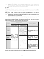
The types and the features of the MAC Address Table are listed as the following:
Type
Configuration
Way
Aging out
Being kept after Relationship between the
reboot
bound MAC address and
(if the configuration the port
is saved)
Static
Manually
Address Table configuring
No
Yes
The bound MAC address
can not be learned by the
other ports in the same
VLAN.
Dynamic
Automatically
Address Table learning
Yes
No
The bound MAC address
can be learned by the other
ports in the same VLAN.
Filtering
Manually
Address Table configuring
No
Yes
-
Table 5-1 Types and features of Address Table
33
This function includes four submenus: Address Table, Static Address, Dynamic Address and
Filtering Address.
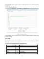
5.4.1 Address Table
On this page, you can view all the information of the Address Table.
Choose the menu Switching→MAC Address→Address Table to load the following page.
Figure 5-11 Address Table
The following entries are displayed on this screen:
Search Option
MAC Address:
Enter the MAC address of your desired entry.
VLAN ID:
Enter the VLAN ID of your desired entry.
Port:
Select the corresponding port number of your desired entry.
Type:
Select the type of your desired entry.
All: This option allows the address table to display all the
address entries.
Static: This option allows the address table to display the static
address entries only.
Dynamic: This option allows the address table to display the
dynamic address entries only.
Filtering: This option allows the address table to display the
filtering address entries only.
Address Table
MAC Address:
Displays the MAC address learned by the switch.
VLAN ID:
Displays the corresponding VLAN ID of the MAC address.
Port:
Displays the corresponding Port number of the MAC address.
Type:
Displays the Type of the MAC address.
Aging Status:
Displays the Aging status of the MAC address.
34
5.4.2 Static Address
The static address table maintains the static address entries which can be added or removed
manually, independent of the aging time. In the stable networks, the static MAC address entries
can facilitate the switch to reduce broadcast packets and remarkably enhance the efficiency of
packets forwarding without learning the address. The static MAC address learned by the port with
Port Security enabled in the static learning mode will be displayed in the Static Address Table.
Choose the menu Switching→MAC Address→Static Address to load the following page.
Figure 5-12 Static Address
The following entries are displayed on this screen:
Create Static Address
MAC Address:
Enter the static MAC Address to be bound.
VLAN ID:
Enter the corresponding VLAN ID of the MAC address.
Port:
Select a port from the pull-down list to be bound.
Search Option
Search Option:
Select a Search Option from the pull-down list and click the Search
button to find your desired entry in the Static Address Table.
MAC: Enter the MAC address of your desired entry.
VLAN ID: Enter the VLAN ID number of your desired entry.
Port: Enter the Port number of your desired entry.
Static Address Table
Select:
Select the entry to delete or modify the corresponding port number. It
is multi-optional.
35
MAC Address:
Displays the static MAC Address.
VLAN ID:
Displays the corresponding VLAN ID of the MAC address.
Port:
Displays the corresponding Port number of the MAC address. Here
you can modify the port number to which the MAC address is bound.
The new port should be in the same VLAN.
Type:
Displays the Type of the MAC address.
Aging Status:
Displays the Aging Status of the MAC address.
Note:
1.
If the corresponding port number of the MAC address is not correct, or the connected port (or
the device) has been changed, the switch can not be forward the packets correctly. Please
reset the static address entry appropriately.
2.
If the MAC address of a device has been added to the Static Address Table, connecting the
device to another port will cause its address not to be recognized dynamically by the switch.
Therefore, please ensure the entries in the Static Address Table are correct and valid.
3.
The MAC address in the Static Address Table can not be added to the Filtering Address Table
or bound to a port dynamically.
5.4.3 Dynamic Address
The dynamic address can be generated by the auto-learning mechanism of the switch. The
Dynamic Address Table can update automatically by auto-learning or aging out the MAC address.
To fully utilize the MAC address table, which has a limited capacity, the switch adopts an aging
mechanism for updating the table. That is, the switch removes the MAC address entries related to
a network device if no packet is received from the device within the aging time.
On this page, you can configure the dynamic MAC address entry.
Choose the menu Switching→MAC Address→Dynamic Address to load the following page.
36
Figure 5-13 Dynamic Address
The following entries are displayed on this screen:
Aging Config
Auto Aging:
Allows you to Enable/Disable the Auto Aging feature.
Aging Time:
Enter the Aging Time for the dynamic address.
Search Option
Search Option:
Select a Search Option from the pull-down list and click the Search
button to find your desired entry in the Dynamic Address Table.
MAC: Enter the MAC address of your desired entry.
VLAN ID: Enter the VLAN ID number of your desired entry.
Port: Enter the Port number of your desired entry.
Dynamic Address Table
Select:
Select the entry to delete the dynamic address or to bind the MAC
address to the corresponding port statically. It is multi-optional.
MAC Address:
Displays the dynamic MAC Address.
VLAN ID:
Displays the corresponding VLAN ID of the MAC address.
Port:
Displays the corresponding port number of the MAC address.
Type:
Displays the Type of the MAC address.
Aging Status:
Displays the Aging Status of the MAC address.
Bind:
Click the Bind button to bind the MAC address of your selected entry
to the corresponding port statically.
37
Tips:
Setting aging time properly helps implement effective MAC address aging. The aging time that is
too long or too short results decreases the performance of the switch. If the aging time is too long,
excessive invalid MAC address entries maintained by the switch may fill up the MAC address table.
This prevents the MAC address table from updating with network changes in time. If the aging time
is too short, the switch may remove valid MAC address entries. This decreases the forwarding
performance of the switch. It is recommended to keep the default value.
5.4.4 Filtering Address
The filtering address is to forbid the undesired packets to be forwarded. The filtering address can
be added or removed manually, independent of the aging time. The filtering MAC address allows
the switch to filter the packets which includes this MAC address as the source address or
destination address, so as to guarantee the network security. The filtering MAC address entries
act on all the ports in the corresponding VLAN.
Choose the menu Switching→MAC Address→Filtering Address to load the following page.
Figure 5-14 Filtering Address
The following entries are displayed on this screen:
Create Filtering Address
MAC Address:
Enter the MAC Address to be filtered.
VLAN ID:
Enter the corresponding VLAN ID of the MAC address.
Search Option
Search Option:
Select a Search Option from the pull-down list and click the Search
button to find your desired entry in the Filtering Address Table.
MAC: Enter the MAC address of your desired entry.
VLAN ID: Enter the VLAN ID number of your desired entry.
38
Filtering Address Table
Select:
Select the entry to delete the corresponding filtering address. It is
multi-optional.
MAC Address:
Displays the filtering MAC Address.
VLAN ID:
Displays the corresponding VLAN ID.
Port:
Here the symbol “__” indicates no specified port.
Type:
Displays the Type of the MAC address.
Aging Status:
Displays the Aging Status of the MAC address.
Note:
The MAC address in the Filtering Address Table can not be added to the Static Address Table or
bound to a port dynamically.
Return to CONTENTS
39
Chapter 6 VLAN
The traditional Ethernet is a data network communication technology based on CSMA/CD (Carrier
Sense Multiple Access/Collision Detect) via shared communication medium. Through the
traditional Ethernet, the overfull hosts in LAN will result in serious collision, flooding broadcasts,
poor performance or even breakdown of the Internet. Though connecting the LANs through
switches can avoid the serious collision, the flooding broadcasts can not be prevented, which will
occupy plenty of bandwidth resources, causing potential serious security problems.
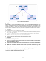
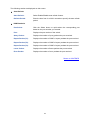
A Virtual Local Area Network (VLAN) is a network topology configured according to a logical
scheme rather than the physical layout. The VLAN technology is developed for switches to control
broadcast in LANs. By creating VLANs in a physical LAN, you can divide the LAN into multiple
logical LANs, each of which has a broadcast domain of its own. Hosts in the same VLAN
communicate with one another as if they are in a LAN. However, hosts in different VLANs cannot
communicate with one another directly. Therefore, broadcast packets are limited in a VLAN. Hosts
in the same VLAN communicate with one another via Ethernet whereas hosts in different VLANs
communicate with one another through the Internet devices such as Router, the Lay3 Switch and
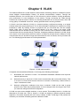
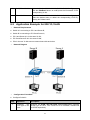
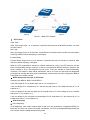
etc. The following figure illustrates a VLAN implementation.
Figure 6-1 VLAN implementation
Compared with the traditional Ethernet, VLAN enjoys the following advantages.
(1) Broadcasts are confined to VLANs. This decreases bandwidth utilization and improves
network performance.
(2) Network security is improved. VLANs cannot communicate with one another directly. That
is, a host in a VLAN cannot access resources in another VLAN directly, unless routers or
Layer 3 switches are used.
(3) Network configuration workload for the host is reduced. VLAN can be used to group
specific hosts. When the physical position of a host changes within the range of the VLAN,
you need not change its network configuration.
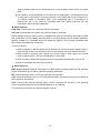
A VLAN can span across multiple switches, or even routers. This enables hosts in a VLAN to be
dispersed in a looser way. That is, hosts in a VLAN can belong to different physical network
segments. This switch supports 802.1Q VLAN to classify VLANs. VLAN tags in the packets are
necessary for the switch to identify packets of different VLANs.
40
6.1 802.1Q VLAN
VLAN tags in the packets are necessary for the switch to identify packets of different VLANs. The
switch works at the data link layer in OSI model and it can identify the data link layer encapsulation
of the packet only, so you can add the VLAN tag field into the data link layer encapsulation for
identification.
In 1999, IEEE issues the IEEE 802.1Q protocol to standardize VLAN implementation, defining the
structure of VLAN-tagged packets. IEEE 802.1Q protocol defines that a 4-byte VLAN tag is
encapsulated after the destination MAC address and source MAC address to show the information
about VLAN.
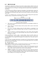
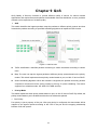
As shown in the following figure, a VLAN tag contains four fields, including TPID (Tag Protocol
Identifier), Priority, CFI (Canonical Format Indicator), and VLAN ID.
Figure 6-2 Format of VLAN Tag
(1) TPID: TPID is a 16-bit field, indicating that this data frame is VLAN-tagged. By default, it is
0x8100 in this switch.
(2) Priority: Priority is a 3-bit field, referring to 802.1p priority. Refer to section “QoS & QoS
profile” for details.
(3) CFI: CFI is a 1-bit field, indicating whether the MAC address is encapsulated in the
standard format in different transmission media. This field is not described in detail in this
chapter.
(4) VLAN ID: VLAN ID is a 12-bit field, indicating the ID of the VLAN to which this packet
belongs. It is in the range of 0 to 4,095. Generally, 0 and 4,095 is not used, so the field is in
the range of 1 to 4,094.
VLAN ID identifies the VLAN to which a packet belongs. When the switch receives an
un-VLAN-tagged packet, it will encapsulate a VLAN tag with the default VLAN ID of the inbound
port for the packet, and the packet will be assigned to the default VLAN of the inbound port for
transmission.
In this User Guide, the tagged packet refers to the packet with VLAN tag whereas the untagged
packet refers to the packet without VLAN tag, and the priority-tagged packet refers to the packet
with VLAN tag whose VLAN ID is 0.
Link Types of ports
When creating the 802.1Q VLAN, you should set the link type for the port according to its
connected device. The link types of port including the following three types:
(1) ACCESS: The ACCESS port can be added in a single VLAN, and the egress rule of the
port is UNTAG. The PVID is same as the current VLAN ID. If the ACCESS port is added to
another VLAN, it will be removed from the current VLAN automatically.
(2) TRUNK: The TRUNK port can be added in multiple VLANs, and the egress rule of the port
is TAG. The TRUNK port is generally used to connect the cascaded network devices for it
can receive and forward the packets of multiple VLANs. When the packets are forwarded
by the TRUNK port, its VLAN tag will not be changed.
41
(3) GENERAL: The GENERAL port can be added in multiple VLANs and set various egress
rules according to the different VLANs. The default egress rule is UNTAG. The PVID can
be set as the VID number of any VLAN the port belongs to.
PVID
PVID (Port Vlan ID) is the default VID of the port. When the switch receives an un-VLAN-tagged
packet, it will add a VLAN tag to the packet according to the PVID of its received port and forward
the packets.
When creating VLANs, the PVID of each port, indicating the default VLAN to which the port
belongs, is an important parameter with the following two purposes:
(1) When the switch receives an un-VLAN-tagged packet, it will add a VLAN tag to the packet
according to the PVID of its received port
(2) PVID determines the default broadcast domain of the port, i.e. when the port receives UL
packets or broadcast packets, the port will broadcast the packets in its default VLAN.
Different packets, tagged or untagged, will be processed in different ways, after being received by
ports of different link types, which is illustrated in the following table.
Receiving Packets
Port Type
Forwarding Packets
Untagged Packets
If the VID of packet is
the same as the PVID
of the port, the packet
will be received.
Access
Trunk
General
Tagged Packets
When
untagged
packets
are
received, the port
will add the default
VLAN tag, i.e. the
PVID of the ingress
port, to the packets.
If the VID of packet is
not the same as the
PVID of the port, the
packet will be dropped.
The
packet
will
be
forwarded after removing its
VLAN tag.
The
packet
will
be
forwarded with its current
VLAN tag.
If the VID of packet is
allowed by the port, the
packet will be received.
If the VID of packet is
forbidden by the port,
the packet will be
dropped.
If the egress rule of port is
TAG, the packet will be
forwarded with its current
VLAN tag.
If the egress rule of port is
UNTAG, the packet will be
forwarded after removing its
VLAN tag.
Table 6-1 Relationship between Port Types and VLAN Packets Processing
IEEE 802.1Q VLAN function is implemented on the VLAN Config and Port Config pages.
42
6.1.1 VLAN Config
On this page, you can view the current created 802.1Q VLAN.
Choose the menu VLAN→802.1Q VLAN→VLAN Config to load the following page.
Figure 6-3 VLAN Table
To ensure the normal communication of the factory switch, the default VLAN of all ports is set to
VLAN1. The Web Management Page of switch can only be accessed through the ports in VLAN1.
VLAN1 can not be modified or deleted.
The following entries are displayed on this screen:
VLAN Table
VLAN ID Select:
Click the Select button to quick-select the corresponding entry
based on the VLAN ID number you entered.
Select:
Select the desired entry to delete the corresponding VLAN. It is
multi-optional.
VLAN ID:
Displays the ID number of VLAN.
Description:
Displays the user-defined description of VLAN.
Members:
Displays the port members in the VLAN.
Operation:
Allows you to view or modify the information for each entry.
Edit: Click to modify the settings of VLAN.
Detail: Click to get the information of VLAN.
Click Edit button to modify the settings of the corresponding VLAN. Click Create button to create a
new VLAN.
43
Figure 6-4 Create or Modify 802.1Q VLAN
The following entries are displayed on this screen:
VLAN Config
VLAN ID:
Enter the ID number of VLAN.
Description:
Give a description to the VLAN for identification.
Check:
Click the Check button to check whether the VLAN ID you entered
is valid or not.
VLAN Members
Port Select:
Click the Select button to quick-select the corresponding entry
based on the port number you entered.
Select:
Select the desired port to be a member of VLAN or leave it blank.
It's multi-optional.
Port:
Displays the port number.
Link Type:
Displays the Link Type of the port. It can be reset on Port Config
screen.
44
Egress Rule:
LAG:
Select the Egress Rule for the VLAN port member. The default
egress rule is UNTAG.
TAG: All packets forwarded by the port are tagged. The
packets contain VLAN information.
UNTAG: Packets forwarded by the port
Displays the LAG to which the port belongs.
6.1.2 Port Config
Before creating the 802.1Q VLAN, please acquaint yourself with all the devices connected to the
switch in order to configure the ports properly.
Choose the menu VLAN→802.1Q VLAN→Port Config to load the following page.
Figure 6-5 802.1Q VLAN – Port Config
The following entries are displayed on this screen:
VLAN Port Config
Port Select:
Click the Select button to quick-select the corresponding entry
based on the port number you entered.
Select:
Select the desired port for configuration. It is multi-optional.
Port:
Displays the port number.
45
Select the Link Type from the pull-down list for the port.
Link Type:
ACCESS: The ACCESS port can be added in a single VLAN,
and the egress rule of the port is UNTAG. The PVID is same
as the current VLAN ID. If the current VLAN is deleted, the
PVID will be set to 1 by default.
TRUNK: The TRUNK port can be added in multiple VLANs,
and the egress rule of the port is TAG. The PVID can be set
as the VID number of any VLAN the port belongs to.
GENERAL: The GENERAL port can be added in multiple
VLANs and set various egress rules according to the
different VLANs. The default egress rule is UNTAG. The
PVID can be set as the VID number of any VLAN the port
belongs to.
PVID:
Enter the PVID number of the port.
LAG:
Displays the LAG to which the port belongs.
VLAN:
Click the Detail button to view the information of the VLAN to
which the port belongs.
Click the Detail button to view the information of the corresponding VLAN
Figure 6-6 View the Current VLAN of Port
The following entries are displayed on this screen:
VLAN of Port
VLAN ID Select:
Click the Select button to quick-select the corresponding entry
based on the VLAN ID number you entered.
VLAN ID:
Displays the ID number of VLAN.
VLAN Description:
Displays the user-defined description of VLAN.
Operation:
Allows you to remove the port from the current VLAN.
Configuration Procedure:
Step
Operation
Description
1
Set the link type for
port.
Required. On the VLAN→802.1Q VLAN→Port Config page, set
the link type for the port based on its connected device.
2
Create VLAN.
Required. On the VLAN→802.1Q VLAN→VLAN Config page,
click the Create button to create a VLAN. Enter the VLAN ID and
the description for the VLAN. Meanwhile, specify its member
ports.
46
3
Modify/View VLAN.
Optional. On the VLAN→802.1Q VLAN→VLAN Config page,
click the Edit/Detail button to modify/view the information of the
corresponding VLAN.
4
Delete VLAN
Optional. On the VLAN→802.1Q VLAN→VLAN Config page,
select the desired entry to delete the corresponding VLAN by
clicking the Delete button.
6.2 Application Example for 802.1Q VLAN
Network Requirements
Switch A is connecting to PC A and Server B;
Switch B is connecting to PC B and Server A;
PC A and Server A is in the same VLAN;
PC B and Server B is in the same VLAN;
PCs in the two VLANs cannot communicate with each other.
Network Diagram
Configuration Procedure
Configure Switch A
Step
1
Operation
Description
Configure
the
Link Type of the
ports
Required. On VLAN→802.1Q VLAN→Port Config page, configure
the link type of Port 2, Port 3 and Port 4 as ACCESS, TRUNK and
ACCESS respectively
47
2
Create VLAN10
Required. On VLAN→802.1Q VLAN→VLAN Config page, create a
VLAN with its VLANID as 10, owning Port 2 and Port 3.
3
Create VLAN20
Required. On VLAN→802.1Q VLAN→VLAN Config page, create a
VLAN with its VLANID as 20, owning Port 3 and Port 4.
Configure Switch B
Step
Operation
Description
1
Configure
the
Link Type of the
ports
Required. On VLAN→802.1Q VLAN→Port Config page, configure
the link type of Port 7, Port 6 and Port 8 as ACCESS, TRUNK and
ACCESS respectively.
2
Create VLAN10
Required. On VLAN→802.1Q VLAN→VLAN Config page, create a
VLAN with its VLANID as 10, owning Port 6 and Port 8.
3
Create VLAN20
Required. On VLAN→802.1Q VLAN→VLAN Config page, create a
VLAN with its VLANID as 20, owning Port 6 and Port 7.
Return to CONTENTS
48
Chapter 7 Spanning Tree
STP (Spanning Tree Protocol), subject to IEEE 802.1D standard, is to disbranch a ring network in
the Data Link layer in a local network. Devices running STP discover loops in the network and block
ports by exchanging information, in that way, a ring network can be disbranched to form a
tree-topological ring-free network to prevent packets from being duplicated and forwarded endlessly
in the network.
BPDU (Bridge Protocol Data Unit) is the protocol data that STP and RSTP use. Enough
information is carried in BPDU to ensure the spanning tree generation. STP is to determine the
topology of the network via transferring BPDUs between devices.
To implement spanning tree function, the switches in the network transfer BPDUs between each
other to exchange information and all the switches supporting STP receive and process the
received BPDUs. BPDUs carry the information that is needed for switches to figure out the
spanning tree.
STP Elements
Bridge ID(Bridge Identifier): Indicates the value of the priority and MAC address of the bridge.
Bridge ID can be configured and the switch with the lower bridge ID has the higher priority.
Root Bridge: Indicates the switch has the lowest bridge ID. Configure the best PC in the ring
network as the root bridge to ensure best network performance and reliability.
Designated Bridge: Indicates the switch has the lowest path cost from the switch to the root
bridge in each network segment. BPDUs are forwarded to the network segment through the
designated bridge. The switch with the lowest bridge ID will be chosen as the designated bridge.
Root Path Cost: Indicates the sum of the path cost of the root port and the path cost of all the
switches that packets pass through. The root path cost of the root bridge is 0.
Bridge Priority: The bridge priority can be set to a value in the range of 0~32768. The lower value
priority has the higher priority. The switch with the higher priority has more chance to be chosen as
the root bridge.
Root Port: Indicates the port that has the lowest path cost from this bridge to the Root Bridge and
forwards packets to the root.
Designated Port: Indicates the port that forwards packets to a downstream network segment or
switch.
Port Priority: The port priority can be set to a value in the range of 0~255. The lower value priority
has the higher priority. The port with the higher priority has more chance to be chosen as the root
port.
Path Cost: Indicates the parameter for choosing the link path by STP. By calculating the path cost,
STP chooses the better links and blocks the redundant links so as to disbranch the ring-network to
form a tree-topological ring-free network.
The following network diagram shows the sketch map of spanning tree. Switch A, B and C are
connected together in order. After STP generation, switch A is chosen as root bridge, the path from
port 2 to port 6 is blocked.
Bridge: Switch A is the root bridge in the whole network; switch B is the designated bridge of
switch C.
Port: Port 3 is the root port of switch B and port 5 is the root port of switch C; port 1 is the
designated port of switch A and port 4 is the designated port of switch B; port 6 is the blocked
port of switch C.
49
Figure 7-1 Basic STP diagram
STP Timers
Hello Time:
Hello Time ranges from 1 to 10 seconds. It specifies the interval to send BPDU packets. It is used
to test the links.
Max. Age:
Max. Age ranges from 6 to 40 seconds. It specifies the maximum time the switch can wait without
receiving a BPDU before attempting to reconfigure.
Forward Delay:
Forward Delay ranges from 4 to 30 seconds. It specifies the time for the port to transit its state
after the network topology is changed.
When the STP regeneration caused by network malfunction occurs, the STP structure will get
some corresponding change. However, as the new configuration BPDUs cannot be spread in the
whole network at once, the temporal loop will occur if the port transits its state immediately.
Therefore, STP adopts a state transit mechanism, that is, the new root port and the designated
port begins to forward data after twice forward delay, which ensures the new configuration BPDUs
are spread in the whole network.
BPDU Comparing Principle in STP mode
Assuming two BPDUs: BPDU X and BPDU Y
If the root bridge ID of X is smaller than that of Y, X is superior to Y.
If the root bridge ID of X equals that of Y, but the root path cost of X is smaller than that of Y, X is
superior to Y.
If the root bridge ID and the root path cost of X equal those of Y, but the bridge ID of X is smaller
than that of Y, X is superior to Y.
If the root bridge ID, the root path cost and bridge ID of X equal those of Y, but the port ID of X is
smaller than that of Y, X is superior to Y.
STP Generation
In the beginning
In the beginning, each switch regards itself as the root, and generates a configuration BPDU for
each port on it as a root, with the root path cost being 0, the ID of the designated bridge being that
of the switch, and the designated port being itself.
50
Comparing BPDUs
Each switch sends out configuration BPDUs and receives a configuration BPDU on one of its ports
from another switch. The following table shows the comparing operations.
Step
Operation
1
If the priority of the BPDU received on the port is lower than that of the BPDU if of
the port itself, the switch discards the BPDU and does not change the BPDU of
the port.
2
If the priority of the BPDU is higher than that of the BPDU of the port itself, the
switch replaces the BPDU of the port with the received one and compares it with
those of other ports on the switch to obtain the one with the highest priority.
Table 7-1 Comparing BPDUs
Selecting the root bridge
The root bridge is selected by BPDU comparing. The switch with the smallest root ID is chosen as
the root bridge.
Selecting the root port and designate port
The operation is taken in the following way:
Step
Operation
1
For each switch (except the one chosen as the root bridge) in a network, the port
that receives the BPDU with the highest priority is chosen as the root port of the
switch.
2
Using the root port BPDU and the root path cost, the switch generates a
designated port BPDU for each of its ports.
3
Root ID is replaced with that of the root port;
Root path is replaced with the sum of the root path cost of the root port and
the path cost between this port and the root port;
The ID of the designated bridge is replaced with that of the switch;
The ID of the designated port is replaced with that of the port.
The switch compares the resulting BPDU with the BPDU of the desired port
whose role you want to determine.
If the resulting BPDU takes the precedence over the BPDU of the port, the
port is chosen as the designated port and the BPDU of this port is replaced
with the resulting BPDU. The port regularly sends out the resulting BPDU;
If the BPDU of this port takes the precedence over the resulting BPDU, the
BPDU of this port is not replaced and the port is blocked. The port only can
receive BPDUs.
Table 7-2 Selecting root port and designated port
Tips:
In a STP with stable topology, only the root port and designated port can forward data, and the
other ports are blocked. The blocked ports only can receive BPDUs.
RSTP (Rapid Spanning Tree Protocol), evolved from the 802.1D STP standard, enable Ethernet
ports to transit their states rapidly. The premises for the port in the RSTP to transit its state rapidly
are as follows.
The condition for the root port to transit its port state rapidly: The old root port of the switch
51
stops forwarding data and the designated port of the upstream switch begins to forward
data.
The condition for the designated port to transit its port state rapidly: The designated port is
an edge port or connecting to a point-to-point link. If the designated port is an edge port, it
can directly transit to forwarding state; if the designated port is connecting to a
point-to-point link, it can transit to forwarding state after getting response from the
downstream switch through handshake.
RSTP Elements
Edge Port: Indicates the port connected directly to terminals.
P2P Link: Indicates the link between two switches directly connected.
MSTP (Multiple Spanning Tree Protocol), compatible with both STP and RSTP and subject to IEEE
802.1s standard, not only enables spanning trees to converge rapidly, but also enables packets of
different VLANs to be forwarded along their respective paths so as to provide redundant links
with a better load-balancing mechanism.
Features of MSTP:
MSTP combines VLANs and spanning tree together via VLAN-to-instance mapping table. It
binds several VLANs to an instance to save communication cost and network resources.
MSTP divides a spanning tree network into several regions. Each region has several
internal spanning trees, which are independent of each other.
MSTP provides a load-balancing mechanism for the packets transmission in the VLAN.
MSTP is compatible with both STP and RSTP.
MSTP Elements
MST Region (Multiple Spanning Tree Region): An MST Region comprises switches with the same
region configuration and VLAN-to-Instances mapping relationship.
IST (Internal Spanning Tree): An IST is a spanning tree in an MST.
CST (Common Spanning Tree): A CST is the spanning tree in a switched network that connects all
MST regions in the network.
CIST (Common and Internal Spanning Tree): A CIST, comprising IST and CST, is the spanning
tree in a switched network that connects all switches in the network.
The following figure shows the network diagram in MSTP.
52
Figure 7-2 Basic MSTP diagram
MSTP
MSTP divides a network into several MST regions. The CST is generated between these MST
regions, and multiple spanning trees can be generated in each MST region. Each spanning tress
is called an instance. As well as STP, MSTP uses BPDUs to generate spanning tree. The only
difference is that the BPDU for MSTP carry the MSTP configuration information on the switches.
Port States
In an MSTP, ports can be in the following four states:
Forwarding: In this status the port can receive/forward data, receive/send BPDU packets as
well as learn MAC address.
Learning: In this status the port can receive/send BPDU packets and learn MAC address.
Blocking: In this status the port can only receive BPDU packets.
Disconnected: In this status the port is not participating in the STP.
Port Roles
In an MSTP, the following roles exist:
Root Port: Indicates the port that has the lowest path cost from this bridge to the Root Bridge
and forwards packets to the root.
Designated Port: Indicates the port that forwards packets to a downstream network segment
or switch.
Master Port: Indicates the port that connects a MST region to the common root. The path
from the master port to the common root is the shortest path between this MST region and
the common root.
Alternate Port: Indicates the port that can be a backup port of a root or master port.
Backup Port: Indicates the port that is the backup port of a designated port.
Disabled: Indicates the port that is not participating in the STP.
The following diagram shows the different port roles.
53
Figure 7-3 Port roles
The Spanning Tree module is mainly for spanning tree configuration of the switch, including four
submenus: STP Config, Port Config, MSTP Instance and STP Security.
7.1 STP Config
The STP Config function, for global configuration of spanning trees on the switch, can be
implemented on STP Config and STP Summary pages.
7.1.1 STP Config
Before configuring spanning trees, you should make clear the roles each switch plays in each
spanning tree instance. Only one switch can be the root bridge in each spanning tree instance. On
this page you can globally configure the spanning tree function and related parameters.
Choose the menu Spanning Tree→STP Config→STP Config to load the following page.
Figure 7-4 STP Config
54
The following entries are displayed on this screen:
Global Config
STP:
Select Enable/Disable STP function globally on the switch.
Version:
Select the desired STP version on the switch.
STP: Spanning Tree Protocol.
RSTP: Rapid Spanning Tree Protocol.
MSTP: Multiple Spanning Tree Protocol.
Parameters Config
CIST Priority:
Enter a value from 0 to 61440 to specify the priority of the switch
for comparison in the CIST. CIST priority is an important criterion
on determining the root bridge. In the same condition, the switch
with the highest priority will be chosen as the root bridge. The
lower value has the higher priority. The default value is 32768 and
should be exact divisor of 4096.
Hello Time
Enter a value from 1 to 10 in seconds to specify the interval to
send BPDU packets. It is used to test the links. 2*(Hello Time + 1)
≤ Max Age. The default value is 2 seconds.
Max Age:
Enter a value from 6 to 40 in seconds to specify the maximum
time the switch can wait without receiving a BPDU before
attempting to reconfigure. The default value is 20 seconds.
Forward Delay:
Enter a value from 4 to 30 in seconds to specify the time for the
port to transit its state after the network topology is changed.
2*(Forward Delay-1) ≥ Max Age. The default value is 15 seconds.
TxHold Count:
Enter a value from 1 to 20 to set the maximum number of BPDU
packets transmitted per Hello Time interval. The default value is
5pps.
Max Hops:
Enter a value from 1 to 40 to set the maximum number of hops
that occur in a specific region before the BPDU is discarded. The
default value is 20 hops.
Note:
1.
The forward delay parameter and the network diameter are correlated. A too small forward
delay parameter may result in temporary loops. A too large forward delay may cause a
network unable to resume the normal state in time. The default value is recommended.
2.
An adequate hello time parameter can enable the switch to discover the link failures occurred
in the network without occupying too much network resources. A too large hello time
parameter may result in normal links being regarded as invalid when packets drop occurred in
the links, which in turn result in spanning tree being regenerated. A too small hello time
parameter may result in duplicated configuration being sent frequently, which increases the
network load of the switches and wastes network resources. The default value is
recommended.
3.
A too small max age parameter may result in the switches regenerating spanning trees
frequently and cause network congestions to be falsely regarded as link problems. A too large
max age parameter result in the switches unable to find the link problems in time, which in
turn handicaps spanning trees being regenerated in time and makes the network less
adaptive. The default value is recommended.
4.
If the TxHold Count parameter is too large, the number of MSTP packets being sent in each
hello time may be increased with occupying too much network resources. The default value is
recommended.
55
7.1.2 STP Summary
On this page you can view the related parameters for Spanning Tree function.
Choose the menu Spanning Tree→STP Config→STP Summary to load the following page.
Figure 7-5 STP Summary
7.2 Port Config
On this page you can configure the parameters of the ports for CIST
Choose the menu Spanning Tree→Port Config to load the following page.
56
Figure 7-6 Port Config
The following entries are displayed on this screen:
Port Config
Port Select:
Click the Select button to quick-select the corresponding port based
on the port number you entered.
Select:
Select the desired port for STP configuration. It is multi-optional.
Port:
Displays the port number of the switch.
Status:
Select Enable /Disable STP function for the desired port.
Priority:
Enter a value from 0 to 240 divisible by 16. Port priority is an
important criterion on determining if the port connected to this port
will be chosen as the root port. The lower value has the higher
priority.
ExtPath:
ExtPath Cost is used to choose the path and calculate the path costs
of ports in different MST regions. It is an important criterion on
determining the root port. The lower value has the higher priority.
IntPath:
IntPath Cost is used to choose the path and calculate the path costs
of ports in an MST region. It is an important criterion on determining
the root port. The lower value has the higher priority.
Edge Port:
Select Enable/Disable Edge Port. The edge port can transit its state
from blocking to forwarding rapidly without waiting for forward delay.
P2P Link:
Select the P2P link status. If the two ports in the P2P link are root port
or designated port, they can transit their states to forwarding rapidly
to reduce the unnecessary forward delay.
MCheck:
Select Enable to perform MCheck operation on the port. Unchange
means no MCheck operation.
STP Version:
Displays the STP version of the port.
Port Role:
Displays the role of the port played in the STP Instance.
Root Port: Indicates the port that has the lowest path cost from
57
Port Status:
Displays the working status of the port.
LAG:
this bridge to the Root Bridge and forwards packets to the root.
Designated Port: Indicates the port that forwards packets to a
downstream network segment or switch.
Master Port: Indicates the port that connects a MST region to the
common root. The path from the master port to the common root
is the shortest path between this MST region and the common
root.
Alternate Port: Indicates the port that can be a backup port of a
root or master port.
Backup Port: Indicates the port that is the backup port of a
designated port.
Disabled: Indicates the port that is not participating in the STP.
Forwarding: In this status the port can receive/forward data,
receive/send BPDU packets as well as learn MAC address.
Learning: In this status the port can receive/send BPDU packets
and learn MAC address.
Blocking: In this status the port can only receive BPDU packets.
Disconnected: In this status the port is not participating in the
STP.
Displays the LAG number which the port belongs to.
Note:
1.
Configure the ports connected directly to terminals as edge ports and enable the BPDU
protection function as well. This not only enables these ports to transit to forwarding state
rapidly but also secures your network.
2.
All the links of ports in a LAG can be configured as point-to-point links.
3.
When the link of a port is configured as a point-to-point link, the spanning tree instances
owning this port are configured as point-to-point links. If the physical link of a port is not a
point-to-point link and you forcibly configure the link as a point-to-point link, temporary loops
may be incurred.
7.3 MSTP Instance
MSTP combines VLANs and spanning tree together via VLAN-to-instance mapping table
(VLAN-to-spanning-tree mapping). By adding MSTP instances, it binds several VLANs to an
instance to realize the load balance based on instances.
Only when the switches have the same MST region name, MST region revision and
VLAN-to-Instance mapping table, the switches can be regarded as in the same MST region.
The MSTP Instance function can be implemented on Region Config, Instance Config and
Instance Port Config pages.
7.3.1 Region Config
On this page you can configure the name and revision of the MST region
Choose the menu Spanning Tree→MSTP Instance→Region Config to load the following page.
58
Figure 7-7 Region Config
The following entries are displayed on this screen:
Region Config
Region Name:
Create a name for MST region identification using up to 32 characters.
Revision:
Enter the revision from 0 to 65535 for MST region identification.
7.3.2 Instance Config
Instance Configuration, a property of MST region, is used to describe the VLAN to Instance
mapping configuration. You can assign VLAN to different instances appropriate to your needs.
Every instance is a VLAN group independent of other instances and CIST.
Choose the menu Spanning Tree→MSTP Instance→Instance Config to load the following page.
Figure 7-8 Instance Config
59
The following entries are displayed on this screen:
Instance Table
Instance ID Select:
Click the Select button to quick-select the corresponding Instance ID
based on the ID number you entered.
Select:
Select the desired Instance ID for configuration. It is multi-optional.
Instance:
Displays Instance ID of the switch.
Status:
Select Enable/Disable the instance.
Priority:
Enter the priority of the switch in the instance. It is an important
criterion on determining if the switch will be chosen as the root bridge
in the specific instance.
VLAN ID:
Enter the VLAN ID which belongs to the corresponding instance ID.
After modification here, the previous VLAN ID will be cleared and
mapped to the CIST.
Clear:
Click the Clear button to clear up all VLAN IDs from the instance ID.
The cleared VLAN ID will be automatically mapped to the CIST.
VLAN-Instance Mapping
VLAN ID:
Enter the desired VLAN ID. After modification here, the new VLAN ID
will be added to the corresponding instance ID and the previous
VLAN ID won’t be replaced.
Instance ID:
Enter the corresponding instance ID.
Note:
In a network with both GVRP and MSTP enabled, GVRP packets are forwarded along the CIST. If
you want to broadcast packets of a specific VLAN through GVRP, please be sure to map the VLAN
to the CIST when configuring the MSTP VLAN-instance mapping table. For detailed introduction of
GVRP, please refer to GVRP function page.
7.3.3 Instance Port Config
A port can play different roles in different spanning tree instance. On this page you can configure
the parameters of the ports in different instance IDs as well as view status of the ports in the
specified instance.
Choose the menu Spanning Tree→MSTP Instance→Instance Port Config to load the following
page.
60
Figure 7-9 Instance Port Config
The following entries are displayed on this screen:
Port Config
Instance ID:
Select the desired instance ID for its port configuration.
Port Select:
Click the Select button to quick-select the corresponding port based
on the port number you entered.
Select:
Select the desired port to specify its priority and path cost. It is
multi-optional.
Port:
Displays the port number of the switch.
Priority:
Enter the priority of the port in the instance. It is an important criterion
on determining if the port connected to this port will be chosen as the
root port.
Path Cost:
Path Cost is used to choose the path and calculate the path costs of
ports in an MST region. It is an important criterion on determining the
root port. The lower value has the higher priority.
Port Role:
Displays the role of the port played in the MSTP Instance.
Port Status:
Displays the working status of the port.
LAG:
Displays the LAG number which the port belongs to.
Note:
The port status of one port in different spanning tree instances can be different.
61
Global configuration Procedure for Spanning Tree function:
Step
Operation
Description
1
Make clear roles the switches
play
in
spanning
tree
instances: root bridge or
designated bridge
Preparation.
2
Globally
configure
parameters
MSTP
Required. Enable Spanning Tree function on the switch
and configure MSTP parameters on Spanning
Tree→STP Config→STP Config page.
3
Configure MSTP parameters
for ports
Required. Configure MSTP parameters for ports on
Spanning Tree→Port Config→Port Config page.
4
Configure the MST region
Required. Create MST region and configure the role the
switch plays in the MST region on Spanning
Tree→MSTP Instance→Region Config and Instance
Config page.
5
Configure MSTP parameters
for instance ports
Optional. Configure different instances in the MST region
and configure MSTP parameters for instance ports on
Spanning Tree→MSTP Instance→Instance Port
Config page.
7.4 STP Security
Configuring protection function for devices can prevent devices from any malicious attack against
STP features. The STP Security function can be implemented on Port Protect and TC Protect
pages.
Port Protect function is to prevent the devices from any malicious attack against STP features.
7.4.1 Port Protect
On this page you can configure loop protect feature, root protect feature, TC protect feature,
BPDU protect feature and BPDU filter feature for ports. You are suggested to enable
corresponding protection feature for the qualified ports.
Loop Protect
In a stable network, a switch maintains the states of ports by receiving and processing BPDU
packets from the upstream switch. However, when link congestions or link failures occurred to the
network, a down stream switch does not receive BPDU packets for certain period, which results in
spanning trees being regenerated and roles of ports being reselected, and causes the blocked
ports to transit to forwarding state. Therefore, loops may be incurred in the network.
The loop protect function can suppresses loops. With this function enabled, a port, regardless of
the role it plays in instances, is always set to blocking state, when the port does not receive BPDU
packets from the upstream switch and spanning trees are regenerated, and thereby loops can be
prevented.
Root Protect
A CIST and its secondary root bridges are usually located in the high-bandwidth core region.
Wrong configuration or malicious attacks may result in configuration BPDU packets with higher
priorities being received by the legal root bridge, which causes the current legal root bridge to lose
its position and network topology jitter to occur. In this case, flows that should travel along
62
high-speed links may lead to low-speed links, and network congestion may occur.
To avoid this, MSTP provides root protect function. Ports with this function enabled can only be set
as designated ports in all spanning tree instances. When a port of this type receives BDPU
packets with higher priority, it transits its state to blocking state and stops forwarding packets (as if
it is disconnected from the link). The port resumes the normal state if it does not receive any
configuration BPDU packets with higher priorities for a period of two times of forward delay.
TC Protect
A switch removes MAC address entries upon receiving TC-BPDU packets. If a user maliciously
sends a large amount of TC-BPDU packets to a switch in a short period, the switch will be busy
with removing MAC address entries, which may decrease the performance and stability of the
network.
To prevent the switch from frequently removing MAC address entries, you can enable the TC
protect function on the switch. With TC protect function enabled, if the account number of the
received TC-BPDUs exceeds the maximum number you set in the TC threshold field, the switch
will not performs the removing operation in the TC protect cycle. Such a mechanism prevents the
switch from frequently removing MAC address entries.
BPDU Protect
Ports of the switch directly connected to PCs or servers are configured as edge ports to rapidly
transit their states. When these ports receive BPDUs, the system automatically configures these
ports as non-edge ports and regenerates spanning trees, which may cause network topology jitter.
Normally these ports do not receive BPDUs, but if a user maliciously attact the switch by sending
BPDUs, network topology jitter occurs.
To prevent this attack, MSTP provides BPDU protect function. With this function enabled on the
switch, the switch shuts down the edge ports that receive BPDUs and reports these cases to the
administrator. If a port is shut down, only the administrator can restore it.
BPDU Filter
BPDU filter function is to prevent BPDUs flood in the STP network. If a switch receives malicious
BPDUs, it forwards these BPDUs to the other switched in the network, which may result in
spanning trees being continuously regenerated. In this case, the switch occupying too much CPU
or the protocol status of BPDUs is wrong.
With BPDU filter function enabled, a port does not receive or forward BPDUs, but it sends out its
own BPDUs. Such a mechanism prevents the switch from being attacked by BPDUs so as to
guarantee generation the spanning trees correct.
Choose the menu Spanning Tree→STP Security→Port Protect to load the following page.
63
Figure 7-10 Port Protect
The following entries are displayed on this screen:
Port Protect
Port Select:
Click the Select button to quick-select the corresponding port based
on the port number you entered.
Select:
Select the desired port for port protect configuration. It is
multi-optional.
Port:
Displays the port number of the switch.
Loop Protect:
Loop Protect is to prevent the loops in the network brought by
recalculating STP because of link failures and network congestions.
Root Protect:
Root Protect is to prevent wrong network topology change caused by
the role change of the current legal root bridge.
TC Protect:
TC Protect is to prevent the decrease of the performance and
stability of the switch brought by continuously removing MAC
address entries upon receiving TC-BPDUs in the STP network.
BPDU Protect:
BPDU Protect is to prevent the edge port from being attacked by
maliciously created BPDUs
BPDU Filter:
BPDU Filter is to prevent BPDUs flood in the STP network.
LAG:
Displays the LAG number which the port belongs to.
64
7.4.2 TC Protect
When TC Protect is enabled for the port on Port Protect page, the TC threshold and TC protect
cycle need to be configured on this page.
Choose the menu Spanning Tree→STP Security→TC Protect to load the following page.
Figure 7-11 TC Protect
The following entries are displayed on this screen:
TC Protect
TC Threshold:
Enter a number from 1 to 100. It is the maximum number of the
TC-BPDUs received by the switch in a TC Protect Cycle. The
default value is 20.
TC Protect Cycle:
Enter a value from 1 to 10 to specify the TC Protect Cycle. The
default value is 5.
7.5 Application Example for STP Function
Network Requirements
Switch A, B, C, D and E all support MSTP function.
A is the central switch.
B and C are switches in the convergence layer. D, E and F are switches in the access layer.
There are 6 VLANs labeled as VLAN101-VLAN106 in the network.
All switches run MSTP and belong to the same MST region.
The data in VLAN01, 103 and 105 are transmitted in the STP with B as the root bridge. The
data in VLAN02, 104 and 106 are transmitted in the STP with C as the root bridge.
Network Diagram
65
Configuration Procedure
Configure Switch A:
Step
Operation
Description
1
Configure ports
On VLAN→802.1Q VLAN page, configure the link
type of the related ports as Trunk, and add the ports to
VLAN 101 and VLAN 106. The detailed instructions
can be found in the section 802.1Q VLAN.
2
Enable STP function
On Spanning Tree→STP Config→STP Config page,
enable STP function and select MSTP version.
On Spanning Tree→STP Config→Port Config page,
enable MSTP function for the port.
3
Configure the region name and
the revision of MST region
On Spanning Tree→MSTP Instance→Region
Config page, configure the region as TP-LINK and
keep the default revision setting.
4
Configure
VLAN-to-Instance
mapping table of the MST region
On Spanning Tree→MSTP Instance→Instance
Config page, configure VLAN-to-Instance mapping
table. Map VLAN 101, 103 and 105 to Instance 1; map
VLAN 102, 104 and 106 to Instance 2.
Configure Switch B:
Step
Operation
Description
1
Configure ports
On VLAN→802.1Q VLAN page, configure the link
type of the related ports as Trunk, and add the ports to
VLAN 101 and VLAN 106. The detailed instructions
can be found in the section 802.1Q VLAN.
2
Enable STP function
On Spanning Tree→STP Config→STP Config page,
enable STP function and select MSTP version.
On Spanning Tree→STP Config→Port Config page,
enable MSTP function for the port.
3
Configure the region name and
the revision of MST region
On Spanning Tree→MSTP Instance→Region
Config page, configure the region as TP-LINK and
keep the default revision setting.
4
Configure
VLAN-to-Instance
mapping table of the MST region
On Spanning Tree→MSTP Instance→Instance
Config page, configure VLAN-to-Instance mapping
table. Map VLAN 101, 103 and 105 to Instance 1; map
VLAN 102, 104 and 106 to Instance 2.
5
Configure switch B as the root
bridge of Instance 1
On Spanning Tree→MSTP Instance→Instance
Config page, configure the priority of Instance 1 to be
0.
6
Configure switch B as the
designated bridge of Instance 2
On Spanning Tree→MSTP Instance→Instance
Config page, configure the priority of Instance 2 to be
4096.
66
Configure Switch C:
Step
Operation
Description
1
Configure ports
On VLAN→802.1Q VLAN page, configure the link
type of the related ports as Trunk, and add the ports to
VLAN 101 and VLAN 106. The detailed instructions
can be found in the section 802.1Q VLAN.
2
Enable STP function
On Spanning Tree→STP Config→STP Config
page, enable STP function and select MSTP version.
On Spanning Tree→STP Config→Port Config
page, enable MSTP function for the port.
3
Configure the region name and
the revision of MST region
On Spanning Tree→MSTP Instance→Region
Config page, configure the region as TP-LINK and
keep the default revision setting.
4
Configure
VLAN-to-Instance
mapping table of the MST region
On Spanning Tree→MSTP Instance→Instance
Config page, configure VLAN-to-Instance mapping
table. Map VLAN 101, 103 and 105 to Instance 1;
map VLAN 102, 104 and 106 to Instance 2.
5
Configure switch C as the root
bridge of Instance 1
On Spanning Tree→MSTP Instance→Instance
Config page, configure the priority of Instance 1 to be
4096.
6
Configure switch C as the root
bridge of Instance 2
On Spanning Tree→MSTP Instance→Instance
Config page, configure the priority of Instance 2 to be
0.
Configure Switch D:
Step
Operation
Description
1
Configure ports
On VLAN→802.1Q VLAN page, configure the link
type of the related ports as Trunk, and add the ports to
VLAN 101 and VLAN 106. The detailed instructions
can be found in the section 802.1Q VLAN.
2
Enable STP function
On Spanning Tree→STP Config→STP Config
page, enable STP function and select MSTP version.
On Spanning Tree→STP Config→Port Config
page, enable MSTP function for the port.
3
Configure the region name and
the revision of MST region
On Spanning Tree→MSTP Instance→Region
Config page, configure the region as TP-LINK and
keep the default revision setting.
4
Configure
VLAN-to-Instance
mapping table of the MST region
On Spanning Tree→MSTP Instance→Instance
Config page, configure VLAN-to-Instance mapping
table. Map VLAN 101, 103 and 105 to Instance 1;
map VLAN 102, 104 and 106 to Instance 2.
The configuration procedure for switch E and F is the same with that for switch D.
The topology diagram of the two instances after the topology is stable
For Instance 1 (VLAN 101, 103 and 105), the red paths in the following figure are connected
67
links; the gray paths are the blocked links.
For Instance 2 (VLAN 102, 104 and 106), the blue paths in the following figure are connected
links; the gray paths are the blocked links.
Suggestion for Configuration
Enable TC Protect function for all the ports of switches.
Enable Root Protect function for all the ports of root bridges.
Enable Loop Protect function for the non-edge ports.
Enable BPDU Protect function or BPDU Filter function for the edge ports which are connected to
the PC and server.
Return to CONTENTS
68
Chapter 8 Multicast
Multicast Overview
In the network, packets are sent in three modes: unicast, broadcast and multicast. In unicast, the
source server sends separate copy information to each receiver. When a large number of users
require this information, the server must send many pieces of information with the same content to
the users. Therefore, large bandwidth will be occupied. In broadcast, the system transmits
information to all users in a network. Any user in the network can receive the information, no
matter the information is needed or not.
Point-to-multipoint multimedia business, such as video conferences and VoD (video-on-demand),
plays an important part in the information transmission field. Suppose a point to multi-point service
is required, unicast is suitable for networks with sparsely users, whereas broadcast is suitable for
networks with densely distributed users. When the number of users requiring this information is
not certain, unicast and broadcast deliver a low efficiency. Multicast solves this problem. It can
deliver a high efficiency to send data in the point to multi-point service, which can save large
bandwidth and reduce the network load. In multicast, the packets are transmitted in the following
way as shown in Figure 8-1.
Figure 8-1 Information transmission in the multicast mode
Features of multicast:
1. The number of receivers is not certain. Usually point-to-multipoint transmission is needed;
2. Multiple users receiving the same information form a multicast group. The multicast
information sender just need sends the information to the network device once;
3. Each user can join and leave the multicast group at any time;
4. Real time is highly demanded and certain packets drop is allowed.
69
Multicast Address
1. Multicast IP Address:
As specified by IANA (Internet Assigned Numbers Authority), Class D IP addresses are used as
destination addresses of multicast packets. The multicast IP addresses range from
224.0.0.0~239.255.255.255. The following table displays the range and description of several
special multicast IP addresses.
Multicast IP address range
Description
224.0.0.0~224.0.0.255
Reserved multicast addresses for routing protocols
and other network protocols
224.0.1.0~224.0.1.255
Addresses for video conferencing
239.0.0.0~239.255.255.255
Local management multicast addresses, which are
used in the local network only
Table 8-1 Range of the special multicast IP
2. Multicast MAC Address:
When a unicast packet is transmitted in an Ethernet network, the destination MAC address is the
MAC address of the receiver. When a multicast packet is transmitted in an Ethernet network, the
destination is not a receiver but a group with uncertain number of members, so a multicast MAC
address, a logical MAC address, is needed to be used as the destination address.
As stipulated by IANA, the high-order 24 bits of a multicast MAC address begins with 01-00-5E
while the low-order 23 bits of a multicast MAC address are the low-order 23 bits of the multicast IP
address. The mapping relationship is described as Figure 8-2.
Figure 8-2 Mapping relationship between multicast IP address and multicast MAC address
The high-order 4 bits of the IP multicast address are 1110, identifying the multicast group. Only 23
bits of the remaining low-order 28 bits are mapped to a multicast MAC address. In that way, 5 bits
of the IP multicast address is not utilized. As a result, 32 IP multicast addresses are mapped to the
same MAC addresses.
Multicast Address Table
The switch is forwarding multicast packets based on the multicast address table. As the
transmission of multicast packets can not span the VLAN, the first part of the multicast address
table is VLAN ID, based on which the received multicast packets are forwarded in the VLAN
owning the receiving port. The multicast address table is not mapped to an egress port but a group
port list. When forwarding a multicast packet, the switch looks up the multicast address table
based on the destination multicast address of the multicast packet. If the corresponding entry can
not be found in the table, the switch will broadcast the packet in the VLAN owning the receiving
port. If the corresponding entry can be found in the table, it indicates that the destination address
should be a group port list, so the switch will duplicate this multicast data and deliver each port one
copy. The general format of the multicast address table is described as Figure 8-3 below.
VLAN ID
Multicast IP
Port
Figure 8-3 Multicast Address Table
70
IGMP Snooping
In the network, the hosts apply to the near Router for joining (leaving) a multicast group by sending
IGMP (Internet Group Management Protocol) messages. When the up-stream device forwards
down the multicast data, the switch is responsible for sending them to the hosts. IGMP Snooping is
a multicast control mechanism, which can be used on the switch for dynamic registration of the
multicast group. The switch, running IGMP Snooping, manages and controls the multicast group via
listening to and processing the IGMP messages transmitted between the hosts and the multicast
router, thereby effectively prevent multicast groups being broadcasted in the network.
The Multicast module is mainly for multicast management configuration of the switch, including
four submenus: IGMP Snooping, Multicast IP, Multicast Filter and Packet Statistics.
8.1 IGMP Snooping
IGMP Snooping Process
The switch, running IGMP Snooping, listens to the IGMP messages transmitted between the host
and the router, and tracks the IGMP messages and the registered port. When receiving IGMP
report message, the switch adds the port to the multicast address table; when the switch listens to
IGMP leave message from the host, the router sends the Group-Specific Query message of the
port to check if other hosts need this multicast, if yes, the router will receive IGMP report message;
if no, the router will receive no response from the hosts and the switch will remove the port from
the multicast address table. The router regularly sends IGMP query messages. After receiving the
IGMP query messages, the switch will remove the port from the multicast address table if the
switch receives no IGMP report message from the host within a period of time.
IGMP Messages
The switch, running IGMP Snooping, processes the IGMP messages of different types as follows.
1. IGMP Query Message
IGMP query message, sent by the router, falls into two types, IGMP general query message and
IGMP group-specific-query message. The router regularly sends IGMP general message to query
if the multicast groups contain any member. When receiving IGMP leave message, the receiving
port of the router will send IGMP group-specific-query message to the multicast group and the
switch will forward IGMP group-specific-query message to check if other members in the multicast
group of the port need this multicast.
When receiving IGMP general query message, the switch will forward them to all other ports in the
VLAN owning the receiving port. The receiving port will be processed: if the receiving port is not a
router port yet, it will be added to the router port list with its router port time specified; if the
receiving port is already a router port, its router port time will be directly reset.
When receiving IGMP group-specific-query message, the switch will send the group-specific query
message to the members of the multicast group being queried.
2. IGMP Report Message
IGMP report message is sent by the host when it applies for joining a multicast group or responses
to the IGMP query message from the router.
When receiving IGMP report message, the switch will send the report message via the router port
in the VLAN as well as analyze the message to get the address of the multicast group the host
applies for joining. The receiving port will be processed: if the receiving port is a new member port,
it will be added to the multicast address table with its member port time specified; if the receiving
port is already a member port, its member port time will be directly reset.
71
3. IGMP Leave Message
The host, running IGMPv1, does not send IGMP leave message when leaving a multicast group,
as a result, the switch can not get the leave information of the host momentarily. However, after
leaving the multicast group, the host does not send IGMP report message any more, so the switch
will remove the port from the corresponding multicast address table when its member port time
times out. The host, running IGMPv2 or IGMPv3, sends IGMP leave message when leaving a
multicast group to inform the multicast router of its leaving.
When receiving IGMP leave message, the switch will forward IGMP group-specific-query message
to check if other members in the multicast group of the port need this multicast and reset the
member port time to the leave time. When the leave time times out, the switch will remove the port
from the corresponding multicast group. If no other member is in the group after the port is
removed, the switch will remove the whole multicast group and send IGMP leave message to the
router.
IGMP Snooping Fundamentals
1. Ports
Router Port: Indicates the switch port directly connected to the multicast router.
Member Port: Indicates a switch port connected to a multicast group member.
2. Timers
Router Port Time: Within the time, if the switch does not receive IGMP query message from the
router port, it will consider this port is not a router port any more. The default value is 300 seconds.
Member Port Time: Within the time, if the switch does not receive IGMP report message from the
member port, it will consider this port is not a member port any more. The default value is 260
seconds.
Leave Time: Indicates the interval between the switch receiving a leave message from a host and
the switch removing the host from the multicast groups. The default value is 1 second.
The IGMP Snooping function can be implemented on Snooping Config, Port Config, VLAN
Config and Multicast VLAN pages.
8.1.1 Snooping Config
To configure the IGMP Snooping on the switch, please firstly configure IGMP global configuration
and related parameters on this page.
If the multicast address of the received multicast data is not in the multicast address table, the
switch will broadcast the data in the VLAN. When Unknown Multicast Discard feature is enabled,
the switch drops the received unknown multicast so as to save the bandwidth and enhance the
process efficiency of the system. Please configure this feature appropriate to your needs.
Choose the menu Multicast→IGMP Snooping→Snooping Config to load the following page.
72
Figure 8-4 Basic Config
The following entries are displayed on this screen:
Global Config
IGMP Snooping:
Select Enable/Disable IGMP Snooping function globally on the
Switch.
Unknown Multicast:
Select the operation for the switch to process unknown multicast,
Forward or Discard.
IGMP Snooping Status
Description:
Displays IGMP Snooping status.
Member:
Displays the member of the corresponding status.
8.1.2 Port Config
On this page you can configure the IGMP feature for ports of the switch.
Choose the menu Multicast→IGMP Snooping→Port Config to load the following page.
73
Figure 8-5 Port Config
The following entries are displayed on this screen:
Port Config
Port Select:
Click the Select button to quick-select the corresponding port
based on the port number you entered.
Select:
Select the desired port for IGMP Snooping feature configuration.
It is multi-optional.
Port:
Displays the port of the Switch.
IGMP Snooping:
Select Enable/Disable IGMP Snooping for the desired port.
Fast Leave:
Select Enable/Disable Fast Leave feature for the desired port. If
Fast Leave is enabled for a port, the Switch will immediately
remove this port from the multicast group upon receiving IGMP
leave messages.
LAG:
Displays the LAG number which the port belongs to.
Note:
1.
Fast Leave on the port is effective only when the host supports IGMPv2 or IGMPv3.
2.
When both Fast Leave feature and Unknown Multicast Discard feature are enabled, the
leaving of a user connected to a port owning multi-user will result in the other users
intermitting the multicast business.
8.1.3 VLAN Config
Multicast groups established by IGMP Snooping are based on VLANs. On this page you can
configure different IGMP parameters for different VLANs.
Choose the menu Multicast→IGMP Snooping→VLAN Config to load the following page.
74
Figure 8-6 VLAN Config
The following entries are displayed on this screen:
VLAN Config
VLAN ID:
Enter the VLAN ID to enable IGMP Snooping for the desired
VLAN.
Router Port Time:
Specify the aging time of the router port. Within this time, if the
switch doesn’t receive IGMP query message from the router port,
it will consider this port is not a router port any more.
Member Port Time:
Specify the aging time of the member port. Within this time, if the
switch doesn’t receive IGMP report message from the member
port, it will consider this port is not a member port any more.
Leave Time:
Specify the interval between the switch receiving a leave
message from a host and the switch removing the host from the
multicast groups.
Static Router Port:
Select the static router port which is mainly used in the network
with stable topology.
VLAN Table
VLAN ID Select:
Click the Select button to quick-select the corresponding VLAN
ID based on the ID number you entered.
Select:
Select the desired VLAN ID for configuration. It is multi-optional.
75
VLAN ID:
Displays the VLAN ID.
Router Port Time:
Displays the router port time of the VLAN.
Member Port Time:
Displays the member port time of the VLAN.
Leave Time:
Displays the leave time of the VLAN.
Router Port:
Displays the router port of the VLAN.
Note:
The settings here will be invalid when multicast VLAN is enabled
Configuration procedure:
Step
Operation
1
Enable
function
Snooping
Required. Enable IGMP Snooping globally on the switch
and
for
the
port
on
Multicast→IGMP
Snooping→Snooping Config and Port Config page.
2
Configure the multicast
parameters for VLANs
Optional. Configure the multicast parameters for VLANs
on Multicast→IGMP Snooping→VLAN Config page.
IGMP
Description
If a VLAN has no multicast parameters configuration, it
indicates the IGMP Snooping is not enabled in the VLAN,
thus the multicast data in the VLAN will be broadcasted.
8.1.4 Multicast VLAN
In old multicast transmission mode, when users in different VLANs apply for join the same
multicast group, the multicast router will duplicate this multicast information and deliver each
VLAN owning a receiver one copy. This mode wastes a lot of bandwidth.
The problem above can be solved by configuring a multicast VLAN. By adding switch ports to the
multicast VLAN and enabling IGMP Snooping, you can make users in different VLANs share the
same multicast VLAN. This saves the bandwidth since multicast streams are transmitted only
within the multicast VLAN and also guarantees security because the multicast VLAN is isolated
from user VLANS.
Before configuring a multicast VLAN, you should firstly configure a VLAN as multicast VLAN and
add the corresponding ports to the VLAN on the 802.1Q VLAN page. If the multicast VLAN is
enabled, the multicast configuration for other VLANs on the VLAN Config page will be invalid, that
is, the multicast streams will be transmitted only within the multicast VLAN.
Choose the menu Multicast→IGMP Snooping→Multicast VLAN to load the following page.
76
Figure 8-7 Multicast VLAN
The following entries are displayed on this screen:
Multicast VLAN
Multicast VLAN:
Select Enable/Disable Multicast VLAN feature.
VLAN ID:
Enter the VLAN ID of the multicast VLAN.
Router Port Time:
Specify the aging time of the router port. Within this time, if the
switch doesn’t receive IGMP query message from the router port,
it will consider this port is not a router port any more.
Member Port Time:
Specify the aging time of the member port. Within this time, if the
switch doesn’t receive IGMP report message from the member
port, it will consider this port is not a member port any more.
Leave Time:
Specify the interval between the switch receiving a leave
message from a host, and the switch removing the host from the
multicast groups.
Static Router Port:
Select the static router port which is mainly used in the network
with stable topology.
Note:
1.
The router port should be in the multicast VLAN, otherwise the member ports can not receive
multicast streams.
2.
The Multicast VLAN won't take effect unless you first complete the configuration for the
corresponding VLAN owning the port on the 802.1Q VLAN page.
3.
The link type of the member ports in the multicast VLAN can only be GENERAL.
4.
Configure the link type of the router port in the multicast VLAN as TRUNK or configure the
egress rule as TAG and the link type as GENERAL otherwise all the member ports in the
multicast VLAN can not receive multicast streams.
5.
After a multicast VLAN is created, all the IGMP packets will be processed only within the
multicast VLAN.
77
Configuration procedure:
Step
Operation
Description
1
Enable IGMP
function
2
Create a multicast VLAN
Snooping
Required. Enable IGMP Snooping globally on the switch
and
for
the
port
on
Multicast→IGMP
Snooping→Snooping Config and Port Config page.
Required. Create a multicast VLAN and add all the member
ports and router ports to the VLAN on the VLAN→802.1Q
VLAN page.
Configure the link type of the member ports as
GENERAL.
3
Configure parameters
multicast VLAN
for
4
Look over the configuration
Configure the link type of the router ports as TRUNK or
configure the egress rule as tagged GENERAL.
Optional. Enable and configure a multicast VLAN on the
Multicast→IGMP Snooping→Multicast VLAN page.
It is recommended to keep the default time parameters.
If it is successfully configured, the VLAN ID of the multicast
VLAN will be displayed in the IGMP Snooping Status table
on the Multicast→IGMP Snooping→Snooping Config
page.
Application Example for Multicast VLAN:
Network Requirements
Multicast source sends multicast streams via the router, and the streams are transmitted to user A
and user B through the switch.
Router: Its WAN port is connected to the multicast source; its LAN port is connected to the switch.
The multicast packets are transmitted in VLAN3.
Switch: Port 3 is connected to the router and the packets are transmitted in VLAN3; port 4 is
connected to user A and the packets are transmitted in VLAN4; port 5 is connected to user B and
the packets are transmitted in VLAN5.
User A: Connected to Port 4 of the switch.
User B: Connected to port 5 of the switch.
Configure a multicast VLAN, and user A and B receive multicast streams through the multicast
VLAN.
Network Diagram
78
Configuration Procedure
Step
Operation
Description
1
Create VLANs
Create three VLANs with the VLAN ID 3, 4 and 5 respectively,
and specify the description of VLAN3 as Multicast VLAN on
VLAN→802.1Q VLAN page.
2
Configure ports
On VLAN→802.1Q VLAN function pages.
For port 3, configure its link type as GENERAL and its egress rule
as TAG, and add it to VLAN3, VLAN4 and VLAN5.
For port 4, configure its link type as GENERAL and its egress rule
as UNTAG, and add it to VLAN3 and VLAN 4.
For port 5, configure its link type as GENERAL and its egress rule
as UNTAG, and add it to VLAN3 and VLAN 5.
3
Enable
IGMP
Snooping function
Enable IGMP Snooping function globally on Multicast→IGMP
Snooping→Snooping Config page. Enable IGMP Snooping
function for port 3, port4 and port 5 on Multicast→IGMP
Snooping→Port Config page.
4
Enable
VLAN
Multicast
Enable Multicast VLAN, configure the VLAN ID of a multicast
VLAN as 3 and keep the other parameters as default on
Multicast→IGMP Snooping→Multicast VLAN page.
5
Check Multicast VLAN
3-5 and Multicast VLAN 3 will be displayed in the IGMP
Snooping
Status
table
on
the
Multicast→IGMP
Snooping→Snooping Config page.
8.2 Multicast Filter
When IGMP Snooping is enabled, you can specified the multicast IP-range the ports can join so as
to restrict users ordering multicast programs via configuring multicast filter rules.
When applying for a multicast group, the host will send IGMP report message. After receiving the
79
report message, the switch will firstly check the multicast filter rules configured for the receiving
port. If the port can be added to the multicast group, it will be added to the multicast address table;
if the port can not be added to the multicast group, the switch will drop the IGMP report message.
In that way, the multicast streams will not be transmitted to this port, which allows you to control
hosts joining the multicast group.
8.2.1 IP-Range
On this page you can figure the desired IP-ranges to be filtered.
Choose the menu Multicast→Multicast Filter→IP-Range to load the following page.
Figure 8-8 Multicast Filter
The following entries are displayed on this screen:
Create IP-Range
IP Range ID:
Enter the IP-range ID.
Start Multicast IP:
Enter start multicast IP of the IP-range you set.
End Multicast IP:
Enter end multicast IP of the IP-range you set.
IP-Range Table
IP-Range ID Select:
Click the Select button to quick-select the corresponding
IP-range ID based on the ID number you entered.
Select:
Select the desired entry to delete or modify the corresponding
IP-range. It is multi-optional.
IP-Range ID:
Displays IP-range ID.
Start Multicast IP:
Displays start multicast IP of the IP-range.
End Multicast IP:
Displays end multicast IP of the IP-range.
8.2.2 Port Filter
On this page you can configure the multicast filter rules for port. Take the configuration on this
80
page and the configuration on IP-Range page together to function to implement multicast filter
function on the switch.
Choose the menu Multicast→Multicast Filter→Port Filter to load the following page.
Figure 8-9 Port Filter
The following entries are displayed on this screen:
Port Filter Config
Port Select:
Click the Select button to quick-select the corresponding port
based on the port number you entered.
Select:
Select the desired port for multicast filtering. It is multi-optional.
Port:
Displays the port number.
Filter:
Select Enable/Disable multicast filtering feature on the port.
Action Mode:
Select the action mode to process multicast packets when the
multicast IP is in the filtering IP-range.
Permit: Only the multicast packets whose multicast IP is in
the IP-range will be processed.
Deny: Only the multicast packets whose multicast IP is not
in the IP-range will be processed.
Bound IP-Range (ID):
Enter the IP-rang ID the port will be bound to.
Max Groups:
Specify the maximum number of multicast groups to prevent
some ports taking up too much bandwidth.
81
LAG:
Displays the LAG number which the port belongs to.
Note:
1.
Multicast Filter feature can only have effect on the VLAN with IGMP Snooping enabled.
2.
Multicast Filter feature has no effect on static multicast IP.
3.
Up to 5 IP-Ranges can be bound to one port.
Configuration Procedure:
Step
Operation
Description
1
Configure IP-Range
Required. Configure IP-Range to be
Multicast→Multicast Filter→IP-Range page.
2
Configure multicast filter
rules for ports
Optional. Configure multicast filter rules for ports on
Multicast→Multicast Filter→Port Filter page.
filtered
on
8.3 Packet Statistics
On this page you can view the multicast data traffic on each port of the switch, which facilitates you
to monitor the IGMP messages in the network.
Choose the menu Multicast→Packet Statistics to load the following page.
Figure 8-10 Packet Statistics
82
The following entries are displayed on this screen:
Auto Refresh
Auto Refresh:
Select Enable/Disable auto refresh feature.
Refresh Period:
Enter the time from 3 to 300 in seconds to specify the auto refresh
period.
IGMP Statistics
Port Select:
Click the Select button to quick-select the corresponding port
based on the port number you entered.
Port:
Displays the port number of the switch.
Query Packet:
Displays the number of query packets the port received.
Report Packet (V1):
Displays the number of IGMPv1 report packets the port received.
Report Packet (V2):
Displays the number of IGMPv2 report packets the port received.
Report Packet (V3):
Displays the number of IGMPv3 report packets the port received.
Leave Packet:
Displays the number of leave packets the port received.
Error Packet:
Displays the number of error packets the port received.
Return to CONTENTS
83
Chapter 9 QoS
QoS (Quality of Service) functions to provide different quality of service for various network
applications and requirements and optimize the bandwidth resource distribution so as to provide a
network service experience of a better quality.
QoS
This switch classifies the ingress packets, maps the packets to different priority queues and then
forwards the packets according to specified scheduling algorithms to implement QoS function.
Figure 9-1 QoS function
Traffic classification: Identifies packets conforming to certain characters according to certain
rules.
Map: The user can map the ingress packets to different priority queues based on the priority
modes. This switch implements three priority modes based on port, on 802.1P and on DSCP.
Queue scheduling algorithm: When the network is congested, the problem that many packets
compete for resources must be solved, usually in the way of queue scheduling. The switch
supports four schedule modes: SP, WRR, SP+WRR and Equ.
Priority Mode
This switch implements three priority modes based on port, on 802.1P and on DSCP. By default, the
priority mode based on port is enabled and the other two modes are optional.
1. Port Priority
Port priority is just a property of the port. After port priority is configured, the data stream will be
mapped to the egress queues according to the CoS of the port and the mapping relationship
between CoS and queues.
84
2. 802.1P Priority
Figure 9-2 802.1Q frame
As shown in the figure above, each 802.1Q Tag has a Pri field, comprising 3 bits. The 3-bit priority
field is 802.1p priority in the range of 0 to 7. 802.1P priority determines the priority of the packets
based on the Pri value. On the Web management page of the switch, you can configure different
priority tags mapping to the corresponding priority levels, and then the switch determine which
packet is sent preferentially when forwarding packets. The switch processes untagged packets
based on the default priority mode.
3. DSCP Priority
Figure 9-3 IP datagram
As shown in the figure above, the ToS (Type of Service) in an IP header contains 8 bits. The first
three bits indicate IP precedence in the range of 0 to 7. RFC2474 re-defines the ToS field in the IP
packet header, which is called the DS field. The first six bits (bit 0-bit 5) of the DS field indicate
DSCP precedence in the range of 0 to 63. The last 2 bits (bit 6 and bit 7) are reserved. On the Web
management page, you can configure different DS field mapping to the corresponding priority
levels. Non-IP datagram with 802.1Q tag are mapped to different priority levels based on 802.1P
priority mode; the untagged non-IP datagram are mapped based on port priority mode.
Schedule Mode
When the network is congested, the problem that many packets compete for resources must be
solved, usually in the way of queue scheduling. The switch implements four scheduling queues,
TC0, TC1, TC2 and TC3. TC0 has the lowest priority while TC3 has the highest priority. The switch
provides four schedule modes: SP, WRR, SP+WRR and Equ.
1.
SP-Mode: Strict-Priority Mode. In this mode, the queue with higher priority will occupy the
whole bandwidth. Packets in the queue with lower priority are sent only when the queue with
higher priority is empty. The switch has four egress queues labeled as TC0, TC1, TC2 and
TC3. In SP mode, their priorities increase in order. TC3 has the highest priority. The
disadvantage of SP queue is that: if there are packets in the queues with higher priority for a
long time in congestion, the packets in the queues with lower priority will be “starved to death”
because they are not served.
85
Figure 9-4 SP-Mode
2.
WRR-Mode: Weight Round Robin Mode. In this mode, packets in all the queues are sent in
order based on the weight value for each queue and every queue can be assured of a certain
service time. The weight value indicates the occupied proportion of the resource. WRR queue
overcomes the disadvantage of SP queue that the packets in the queues with lower priority
can not get service for a long time. In WRR mode, though the queues are scheduled in order,
the service time for each queue is not fixed, that is to say, if a queue is empty, the next queue
will be scheduled. In this way, the bandwidth resources are made full use of. The default
weight value ratio of TC0, TC1, TC2 and TC3 is 1:2:4:8.
Figure 9-5 WRR-Mode
3.
SP+WRR-Mode: Strict-Priority + Weight Round Robin Mode. In this mode, this switch
provides two scheduling groups, SP group and WRR group. Queues in SP group and WRR
group are scheduled strictly based on strict-priority mode while the queues inside WRR group
follow the WRR mode. In SP+WRR mode, TC3 is in the SP group; TC0, TC1 and TC2 belong
to the WRR group and the weight value ratio of TC0, TC1 and TC2 is 1:2:4. In this way, when
scheduling queues, the switch allows TC3 to occupy the whole bandwidth following the SP
mode and the TC0, TC1 and TC2 in the WRR group will take up the bandwidth according to
their ratio 1:2:4.
4.
Equ-Mode: Equal-Mode. In this mode, all the queues occupy the bandwidth equally. The
weight value ratio of all the queues is 1:1:1:1.
86
The QoS module is mainly for traffic control and priority configuration, including three submenus:
DiffServ and Bandwidth Control.
9.1 DiffServ
This switch classifies the ingress packets, maps the packets to different priority queues and then
forwards the packets according to specified scheduling algorithms to implement QoS function.
This switch implements three priority modes based on port, on 802.1P and on DSCP, and supports
four queue scheduling algorithms. The port priorities are labeled as CoS0, CoS1… CoS7.
The DiffServ function can be implemented on Port Priority, Schedule Mode, 802.1P Priority and
DSCP Priority pages.
9.1.1 Port Priority
On this page you can configure the port priority.
Choose the menu QoS→DiffServ→Port Priority to load the following page.
Figure 9-6 Port Priority Config
The following entries are displayed on this screen:
Port Priority Config
Select:
Select the desired port to configure its priority. It is multi-optional.
Port:
Displays the physical port number of the switch.
Priority:
Specify the priority for the port.
LAG:
Displays the LAG number which the port belongs to.
87
Configuration Procedure:
Step
Operation
Description
1
Select the port priority
Required. On QoS→DiffServ→Port Priority page,
configure the port priority.
2
Configure
the
mapping
relation between the 802.1P
priority and TC
Required. On QoS→DiffServ→802.1P Priority page,
configure the mapping relation between the 802.1P
priority and TC.
3
Select a schedule mode
Required. On QoS→DiffServ→Schedule Mode page,
select a schedule mode.
9.1.2 Schedule Mode
On this page you can select a schedule mode for the switch. When the network is congested, the
problem that many packets compete for resources must be solved, usually in the way of queue
scheduling. The switch will control the forwarding sequence of the packets according to the priority
queues and scheduling algorithms you set. On this switch, the priority levels are labeled as TC0,
TC1… TC3.
Choose the menu QoS→DiffServ→Schedule Mode to load the following page.
Figure 9-7 Schedule Mode
The following entries are displayed on this screen:
Schedule Mode Config
SP-Mode:
Strict-Priority Mode. In this mode, the queue with higher priority
will occupy the whole bandwidth. Packets in the queue with lower
priority are sent only when the queue with higher priority is empty.
WRR-Mode:
Weight Round Robin Mode. In this mode, packets in all the
queues are sent in order based on the weight value for each
queue. The weight value ratio of TC0, TC1, TC2 and TC3 is
1:2:4:8.
SP+WRR-Mode:
Strict-Priority + Weight Round Robin Mode. In this mode, this
switch provides two scheduling groups, SP group and WRR
group. Queues in SP group and WRR group are scheduled
strictly based on strict-priority mode while the queues inside
WRR group follow the WRR mode. In SP+WRR mode, TC3 is in
the SP group; TC0, TC1 and TC2 belong to the WRR group and
the weight value ratio of TC0, TC1 and TC2 is 1:2:4. In this way,
when scheduling queues, the switch allows TC3 to occupy the
whole bandwidth following the SP mode and the TC0, TC1 and
TC2 in the WRR group will take up the bandwidth according to
their ratio 1:2:4.
Equ-Mode:
Equal-Mode. In this mode, all the queues occupy the bandwidth
equally. The weight value ratio of all the queues is 1:1:1:1.
88
9.1.3 802.1P Priority
On this page you can configure 802.1P priority. 802.1P gives the Pri field in 802.1Q tag a
recommended definition. This field is used to divide packets into 8 priorities. When 802.1P Priority is
enabled, the packets with 802.1Q tag are mapped to different priority levels based on 802.1P priority
mode. The untagged packets are mapped based on port priority mode.
Choose the menu QoS→DiffServ→802.1P Priority to load the following page.
Figure 9-8 802.1P Priority
The following entries are displayed on this screen:
Priority Level
Priority Tag:
Indicates the precedence level defined by IEEE802.1P.
Priority Level:
Indicates the priority level the packets with tag are mapped to.
The priority levels are labeled as TC 0, TC1, TC2 and TC3.
Configuration Procedure:
Step
Operation
Description
1
Configure
the
mapping
relation between the 802.1P
priority and TC
Required. On QoS→DiffServ→802.1P Priority page,
configure the mapping relation between the 802.1P
priority and TC.
2
Select a schedule mode
Required. On QoS→DiffServ→Schedule
page,, select a schedule mode.
Mode
9.1.4 DSCP Priority
On this page you can configure DSCP priority. DSCP (DiffServ Code Point) is a new definition to IP
ToS field given by IEEE. This field is used to divide IP datagram into 64 priorities. When DSCP
Priority is enabled, IP datagram are mapped to different priority levels based on DSCP priority
mode; non-IP datagram with 802.1Q tag are mapped to different priority levels based on 802.1P
priority mode if 8021.1P Priority mode is enabled; the untagged non-IP datagram are mapped based
on port priority mode.
Choose the menu QoS→DiffServ→DSCP Priority to load the following page.
89
Figure 9-9 DSCP Priority
The following entries are displayed on this screen:
DSCP Priority Config
DSCP Priority:
Select Enable or Disable DSCP Priority.
Priority Level
DSCP:
Indicates the priority determined by the DS region of IP
datagram. It ranges from 0 to 63.
Priority:
Indicates the 802.1P priority the packets with tag are mapped to.
The priorities are labeled as CoS0 ~ CoS7.
Configuration Procedure:
Step
Operation
Description
1
Configure
the
mapping
relation between the DSCP
priority and 802.1P priority
Required. On QoS→DiffServ→DSCP Priority page,
enable DSCP Priority and configure the mapping
relation between the DSCP priority and 802.1P priority.
1
Configure
the
mapping
relation between the 802.1P
priority and TC
Required. On QoS→DiffServ→802.1P Priority page,
configure the mapping relation between the 802.1P
priority and TC.
2
Select a schedule mode
Required. On QoS→DiffServ→Schedule
page,, select a schedule mode.
90
Mode
9.2 Bandwidth Control
Bandwidth function, allowing you to control the traffic rate and broadcast flow on each port to
ensure network in working order, can be implemented on Rate Limit and Storm Control pages.
9.2.1 Rate Limit
Rate limit functions to control the ingress/egress traffic rate on each port via configuring the
available bandwidth of each port. In this way, the network bandwidth can be reasonably distributed
and utilized.
Choose the menu QoS→Bandwitdth Control→Rate Limit to load the following page.
Figure 9-10 Rate Limit
The following entries are displayed on this screen:
Rate Limit Config
Port Select:
Click the Select button to quick-select the corresponding port
based on the port number you entered.
Select:
Select the desired port for Rate configuration. It is multi-optional.
Port:
Displays the port number of the Switch.
Ingress Rate (bps):
Configure the bandwidth for receiving packets on the port. You
can select a rate from the dropdown list or select "Manual" to set
Ingress rate, the system will automatically select integral multiple
of 64Kbps that closest to the rate you entered as the real Ingress
rate.
91
Egress Rate(bps):
Configure the bandwidth for sending packets on the port. You can
select a rate from the dropdown list or select "Manual" to set
Egress rate, the system will automatically select integral multiple
of 64Kbps that closest to the rate you entered as the real Egress
rate.
LAG:
Displays the LAG number which the port belongs to.
Note:
1.
If you enable ingress rate limit feature for the storm control-enabled port, storm control feature
will be disabled for this port.
2.
W hen selecting "Manual" to set Ingress/Egress rate, the system will automatically select
integral multiple of 64Kbps that closest to the rate you entered as the real Ingress/Egress rate.
For example, if you enter 1000Kbps for egress rate, the system will automatically select
1024Kbps as the real Egress rate.
3.
When egress rate limit feature is enabled for one or more ports, you are suggested to disable
the flow control on each port to ensure the switch works normally.
9.2.2 Storm Control
Storm Control function allows the switch to filter broadcast, multicast and UL frame in the network.
If the transmission rate of the three kind packets exceeds the set bandwidth, the packets will be
automatically discarded to avoid network broadcast storm.
Choose the menu QoS→Bandwitdth Control→Storm Control to load the following page.
Figure 9-11 Storm Control
92
The following entries are displayed on this screen:
Storm Control Config
Port Select:
Click the Select button to quick-select the corresponding port
based on the port number you entered.
Select:
Select the desired port for Storm Control configuration. It is
multi-optional.
Port:
Displays the port number of the Switch.
Broadcast
(bps):
Rate
Select the bandwidth for receiving broadcast packets on the port.
The packet traffic exceeding the bandwidth will be discarded.
Select Disable to disable the storm control function for the port.
Mulitcast
(bps):
Rate
Select the bandwidth for receiving multicast packets on the port.
The packet traffic exceeding the bandwidth will be discarded.
Select Disable to disable the storm control function for the port.
UL-Framce
(bps):
Rate
Select the bandwidth for receiving UL-Frame on the port. The
packet traffic exceeding the bandwidth will be discarded. Select
Disable to disable the storm control function for the port.
LAG:
Displays the LAG number which the port belongs to.
Note:
If you enable storm control feature for the ingress rate limit-enabled port, ingress rate limit feature
will be disabled for this port.
Return to CONTENTS
93
Chapter 10 SNMP
SNMP Overview
SNMP (Simple Network Management Protocol) has gained the most extensive application on the
UDP/IP networks. SNMP provides a management frame to monitor and maintain the network
devices. It is used for automatically managing the various network devices no matter the physical
differences of the devices. Currently, the most network management systems are based on SNMP.
SNMP is simply designed and convenient for use with no need of complex fulfillment procedures
and too much network resources. With SNMP function enabled, network administrators can easily
monitor the network performance, detect the malfunctions and configure the network devices. In
the meantime, they can locate faults promptly and implement the fault diagnosis, capacity planning
and report generating.
SNMP Management Frame
SNMP management frame includes three network elements: SNMP Management Station, SNMP
Agent and MIB (Management Information Base).
SNMP Management Station: SNMP Management Station is the workstation for running the
SNMP client program, providing a friendly management interface for the administrator to manage
the most network devices conveniently.
SNMP Agent: Agent is the server software operated on network devices with the responsibility of
receiving and processing the request packets from SNMP Management Station. In the meanwhile,
Agent will inform the SNMP Management Station of the events whenever the device status
changes or the device encounters any abnormalities such as restarting the device.
MIB: MIB is the set of the managed objects. MIB defines a few attributes of the managed objects,
including the names, the access rights, and the data types. Every SNMP Agent has its own MIB.
The SNMP Management station can read/write the MIB objects based on its management right.
SNMP Management Station is the manager of SNMP network while SNMP Agent is the managed
object. The information between SNMP Management Station and SNMP Agent are exchanged
through SNMP (Simple Network Management Protocol). The relationship among SNMP
Management Station, SNMP Agent and MIB is illustrated in the following figure.
Figure 10-1 Relationship among SNMP Network Elements
SNMP Versions
This switch supports SNMP v3, and is compatible with SNMP 1 and SNMP v2c. The SNMP
versions adopted by SNMP Management Station and SNMP Agent should be the same.
Otherwise, SNMP Management Station and SNMP Agent can not communicate with each other
normally. You can select the management mode with proper security level according to your actual
application requirement.
94
SNMP v1: SNMP v1 adopts Community Name authentication. The community name is used to
define the relation between SNMP Management Station and SNMP Agent. The SNMP packets
failing to pass community name authentication are discarded. The community name can limit
access to SNMP Agent from SNMP NMS, functioning as a password.
SNMP v2c: SNMP v2c also adopts community name authentication. It is compatible with SNMP
v1 while enlarges the function of SNMP v1.
SNMP v3: Based on SNMP v1 and SNMP v2c, SNMP v3 extremely enhances the security and
manageability. It adopts VACM (View-based Access Control Model) and USM (User-Based
Security Model) authentication. The user can configure the authentication and the encryption
functions. The authentication function is to limit the access of the illegal user by authenticating the
senders of packets. Meanwhile, the encryption function is used to encrypt the packets transmitted
between SNMP Management Station and SNMP Agent so as to prevent any information being
stolen. The multiple combinations of authentication function and encryption function can
guarantee a more reliable communication between SNMP Management station and SNMP Agent.
MIB Introduction
To uniquely identify the management objects of the device in SNMP messages, SNMP adopts the
hierarchical architecture to identify the managed objects. It is like a tree, and each tree node
represents a managed object, as shown in the following figure. Thus the object can be identified
with the unique path starting from the root and indicated by a string of numbers. The number string
is the Object Identifier of the managed object. In the following figure, the OID of the managed
object B is {1.2.1.1}. While the OID of the managed object A is {1.2.1.1.5}.
Figure 10-2 Architecture of the MIB tree
SNMP Configuration Outline
1. Create View
The SNMP View is created for the SNMP Management Station to manage MIB objects. The
managed object, uniquely identified by OID, can be set to under or out of the management of
SNMP Management Station by configuring its view type (included/excluded). The OID of managed
object can be found on the SNMP client program running on the SNMP Management Station.
2. Create SNMP Group
After creating the SNMP View, it’s required to create a SNMP Group. The Group Name, Security
Model and Security Level compose the identifier of the SNMP Group. The Groups with these three
items the same are considered to be the same. You can configure SNMP Group to control the
network access by providing the users in various groups with different management rights via the
Read View, Write View and Notify View.
3. Create SNMP User
The User is configured in a SNMP Group can manage the switch via the client program on
95
management station. The specified User Name and the Auth/Privacy Password are used for
SNMP Management Station to access the SNMP Agent, functioning as the password.
SNMP module is used to configure the SNMP function of the switch, including three submenus:
SNMP Config, Notification and RMON.
10.1 SNMP Config
The SNMP Config can be implemented on the Global Config, SNMP View, SNMP Group,
SNMP User and SNMP Community pages.
10.1.1 Global Config
To enable SNMP function, please configure the SNMP function globally on this page.
Choose the menu SNMP→SNMP Config→Global Config to load the following page.
Figure 10-3 Global Config
The following entries are displayed on this screen:
Global Config
SNMP:
Local Engine
Local Engine ID:
Enable/Disable the SNMP function.
Specify the switch’s Engine ID for the remote clients. The
Engine ID is a unique alphanumeric string used to identify the
SNMP engine on the Switch.
Remote Engine
Remote Engine ID:
Specify the Remote Engine ID for switch. The Engine ID is a
unique alphanumeric string used to identify the SNMP engine
on the remote device which receives traps and informs from
switch.
Note:
The amount of Engine ID characters must be even.
96
10.1.2 SNMP View
The OID (Object Identifier) of the SNMP packets is used to describe the managed objects of the
switch, and the MIB (Management Information Base) is the set of the OIDs. The SNMP View is
created for the SNMP management station to manage MIB objects.
Choose the menu SNMP→SNMP Config→SNMP View to load the following page.
Figure 10-4 SNMP View
The following entries are displayed on this screen:
View Config
View Name:
Give a name to the View for identification. Each View can
include several entries with the same name.
MIB Object ID:
Enter the Object Identifier (OID) for the entry of View.
View Type:
Select the type for the view entry.
Include: The view entry can be managed by the SNMP
management station.
Exclude: The view entry can not be managed by the SNMP
management station.
View Table
Select:
Select the desired entry to delete the corresponding view. All
the entries of a View will be deleted together.
View Name:
Displays the name of the View entry.
View Type:
Displays the type of the View entry.
MIB Object ID:
Displays the OID of the View entry.
10.1.3 SNMP Group
On this page, you can configure SNMP Group to control the network access by providing the users
in various groups with different management rights via the Read View, Write View and Notify View.
97
Choose the menu SNMP→SNMP Config→SNMP Group to load the following page.
Figure 10-5 SNMP Group
The following entries are displayed on this screen:
Group Config
Group Name:
Enter the SNMP Group name. The Group Name, Security Model
and Security Level compose the identifier of the SNMP Group.
The Groups with these three items the same are considered to be
the same.
Security Model:
Select the Security Model for the SNMP Group.
Security Level:
v1: SNMPv1 is defined for the group. In this model, the
Community Name is used for authentication. SNMP v1 can be
configured on the SNMP Community page directly.
v2c: SNMPv2c is defined for the group. In this model, the
Community Name is used for authentication. SNMP v2c can be
configured on the SNMP Community page directly.
v3: SNMPv3 is defined for the group. In this model, the USM
mechanism is used for authentication. If SNMPv3 is enabled,
the Security Level field is enabled for configuration.
Select the Security Level for the SNMP v3 Group.
noAuthNoPriv: No authentication and no privacy security
levels are used.
authNoPriv: Only the authentication security level is used.
authPriv: Both the authentication and the privacy security
levels are used.
Read View:
Select the View to be the Read View. The management access is
restricted to read-only, and changes cannot be made to the
assigned SNMP View.
Write View:
Select the View to be the Write View. The management access is
writing only and changes can be made to the assigned SNMP
View. The View defined both as the Read View and the Write View
can be read and modified.
Notify View:
Select the View to be the Notify View. The management station
98
can receive trap messages of the assigned SNMP view generated
by the Switch's SNMP agent.
Group Table
Select:
Select the desired entry to delete the corresponding group. It is
multi-optional.
Group Name:
Displays the Group Name here.
Security Model:
Displays the Security Model of the group.
Security Level:
Displays the Security Level of the group.
Read View:
Displays the Read View name in the entry.
Write View:
Displays the Write View name in the entry.
Notify View:
Displays the Notify View name in the entry.
Operation:
Click the Edit button to modify the Views in the entry and click the
Modify button to apply.
Note:
Every Group should contain a Read View. The default Read View is viewDefault.
10.1.4 SNMP User
The User in a SNMP Group can manage the switch via the management station software. The
User and its Group have the same security level and access right. You can configure the SNMP
User on this page.
Choose the menu SNMP→SNMP Config→SNMP User to load the following page.
Figure 10-6 SNMP User
The following entries are displayed on this screen:
User Config
99
User Name:
Enter the User Name here.
User Type:
Select the type for the User.
Local User: Indicates that the user is connected to a
local SNMP engine.
Remote User: Indicates that the user is connected to a
remote SNMP engine.
Group Name:
Select the Group Name of the User. The User is classified to
the corresponding Group according to its Group Name,
Security Model and Security Level.
Security Model:
Select the Security Model for the User.
Security Level:
Select the Security Level for the SNMP v3 User.
Auth Mode:
Select the Authentication Mode for the SNMP v3 User.
None: No authentication method is used.
MD5: The port authentication
HMAC-MD5 algorithm.
SHA: The port authentication is performed via SHA
(Secure Hash Algorithm). This authentication mode has a
higher security than MD5 mode.
is
performed
Auth Password:
Enter the password for authentication.
Privacy Mode:
Select the Privacy Mode for the SNMP v3 User.
Privacy Password:
None: No privacy method is used.
DES: DES encryption method is used.
via
Enter the Privacy Password.
User Table
Select:
Select the desired entry to delete the corresponding User. It is
multi-optional.
User Name:
Displays the name of the User.
User Type:
Displays the User Type.
Group Name:
Displays the Group Name of the User.
Security Model:
Displays the Security Model of the User.
Security Level:
Displays the Security Level of the User.
Auth Mode:
Displays the Authentication Mode of the User.
Privacy Mode:
Displays the Privacy Mode of the User.
Operation:
Click the Edit button to modify the Group of the User and click
the Modify button to apply.
Note:
The SNMP User and its Group should have the same Security Model and Security Level.
10.1.5 SNMP Community
SNMP v1 and SNMP v2c adopt community name authentication. The community name can limit
access to the SNMP agent from SNMP network management station, functioning as a password. If
100
SNMP v1 or SNMP v2c is employed, you can directly configure the SNMP Community on this
page without configuring SNMP Group and User.
Choose the menu SNMP→SNMP Config→SNMP Community to load the following page.
Figure 10-7 SNMP Community
The following entries are displayed on this screen:
Community Config
Community Name:
Enter the Community Name here.
Access:
Defines the access rights of the community.
MIB View:
read-only: Management right of the Community is
restricted to read-only, and changes cannot be made to
the corresponding View.
read-write: Management right of the Community is
read-write and changes can be made to the corresponding
View.
Select the MIB View for the community to access.
Community Table
Select:
Select the desired entry to delete the corresponding Community. It
is multi-optional.
Community Name:
Displays the Community Name here.
Access:
Displays the right of the Community to access the View.
MIB View:
Displays the Views which the Community can access.
Operation:
Click the Edit button to modify the MIB View and the Access right
of the Community, and then click the Modify button to apply.
Note:
The default MIB View of SNMP Community is viewDefault.
101
Configuration Procedure:
If SNMPv3 is employed, please take the following steps:
Step
Operation
Description
1
Enable SNMP function globally.
Required. On the SNMP→SNMP Config→Global
Config page, enable SNMP function globally.
2
Create SNMP View.
Required. On the SNMP→SNMP Config→SNMP
View page, create SNMP View of the management
agent. The default View Name is viewDefault and
the default OID is 1.
3
Create SNMP Group.
Required. On the SNMP→SNMP Config→SNMP
Group page, create SNMP Group for SNMPv3 and
specify SNMP Views with various access levels for
SNMP Group.
4
Create SNMP User.
Required. On the SNMP→SNMP Config→SNMP
User page, create SNMP User in the Group and
configure the auth/privacy mode and auth/privacy
password for the User.
If SNMPv1 or SNMPv2c is employed, please take the following steps:
Step
Operation
Description
1
Enable SNMP function globally.
Required.
On
the
SNMP→SNMP
Config→Global Config page, enable SNMP
function globally.
2
Create SNMP View.
Required.
On
the
SNMP→SNMP
Config→SNMP View page, create SNMP
View of the management agent. The default
View Name is viewDefault and the default
OID is 1.
3
Create
SNMP
Community
directly.
Configure
access
level for the
User.
Required alternatively.
On the SNMP→SNMP Config→SNMP
Community page, create SNMP
Community based on SNMP v1 and
SNMP v2c.
Create
SNMP
Group
and
SNMP User.
Create SNMP Community directly.
Create SNMP Group and SNMP User.
Similar to the configuration way based
on SNMPv3, you can create SNMP
Group and SNMP User of SNMP v1/v2c.
The User name can limit access to the
SNMP agent from SNMP network
management station, functioning as a
community name. The users can
manage the device via the Read View,
Write View and Notify View defined in
the SNMP Group.
102
10.2 Notification
With the Notification function enabled, the switch can initiatively report to the management station
about the important events that occur on the Views (e.g., the managed device is rebooted), which
allows the management station to monitor and process the events in time.
The notification information includes the following two types:
Trap : Trap is the information that the managed device initiatively sends to the Network
management station without request.
Inform:Inform packet is sent to inform the management station and ask for the reply. The switch
will resend the inform request if it doesn’t get the response from the management station during
the Timeout interval, and it will terminate resending the inform request if the resending times reach
the specified Retry times. The Inform type has a higher security than the Trap type, which is
employed on SNMPv3.
On this page, you can configure the notification function of SNMP.
Choose the menu SNMP→Notification→Notification to load the following page.
Figure 10-8 Notification Config
The following entries are displayed on this screen:
Create Notification
IP Address:
Enter the IP Address of the management Host.
UDP Port:
Enter the number of the UDP port used to send notifications.
The UDP port functions with the IP address for the notification
sending. The default is 162.
User:
Enter the User name of the management station.
Security Model:
Select the Security Model of the management station.
Security Level:
Select the Security Level for the SNMP v3 User.
noAuthNoPriv: No authentication and no privacy security
level are used.
authNoPriv: Only the authentication security level is used.
authPriv: Both the authentication and the privacy security
levels are used.
103
Type:
Select the type for the notifications.
Trap: Indicates traps are sent.
Inform: Indicates informs are sent. The Inform type has a
higher security than the Trap type.
Retry:
Specify the amount of times the switch resends an inform
request. The switch will resend the inform request if it doesn’t
get the response from the management station during the
Timeout interval, and it will terminate resending the inform
request if the resending times reach the specified Retry times.
Timeout:
Specify the maximum time for the switch to wait for the
response from the management station before resending a
request.
Notification Table
Select:
Select the desired
management station.
entry
to
delete
the
corresponding
IP Address:
Displays the IP Address of the management host.
UDP Port:
Displays the UDP port used to send notifications.
User:
Displays the User name of the management station.
Security Model:
Displays the Security Model of the management station.
Security Level:
Displays the Security Level for the SNMP v3 User.
Type:
Displays the type of the notifications.
Timeout:
Displays the maximum time for the switch to wait for the
response from the management station before resending a
request.
Retry:
Displays the amount of times the switch resends an inform
request.
Operation:
Click the Edit button to modify the corresponding entry and click
the Modify button to apply.
10.3 RMON
RMON (Remote Monitoring) based on SNMP (Simple Network Management Protocol)
architecture, functions to monitor the network. RMON is currently a commonly used network
management standard defined by Internet Engineering Task Force (IETF), which is mainly used to
monitor the data traffic across a network segment or even the entire network so as to enable the
network administrator to take the protection measures in time to avoid any network malfunction. In
addition, RMON MIB records network statistics information of network performance and
malfunction periodically, based on which the management station can monitor network at any time
effectively. RMON is helpful for network administrator to manage the large-scale network since it
reduces the communication traffic between management station and managed agent.
RMON Group
This switch supports the following four RMON Groups defined on the RMON standard (RFC1757):
History Group, Event Group, Statistic Group and Alarm Group.
104
RMON Group
Function
History Group
After a history group is configured, the switch collects and records network
statistics information periodically, based on which the management station
can monitor network effectively.
Event Group
Event Group is used to define RMON events. Alarms occur when an event is
detected.
Statistic Group
Statistic Group is set to monitor the statistic of alarm variables on the specific
ports.
Alarm Group
Alarm Group is configured to monitor the specific alarm variables. When the
value of a monitored variable exceeds the threshold, an alarm event is
generated, which triggers the switch to act in the set way.
The RMON Groups can be configured on the History Control, Event Config and Alarm Config
pages.
10.3.1 History Control
On this page, you can configure the History Group for RMON.
Choose the menu SNMP→RMON→History Control to load the following page.
Figure 10-9 History Control
The following entries are displayed on this screen:
History Control Table
Select:
Select the desired entry for configuration.
Index:
Displays the index number of the entry.
Port:
Specify the port from which the history samples were taken.
Interval:
Specify the interval to take samplings from the port.
Owner:
Enter the name of the device or user that defined the entry.
105
Status:
Select Enable/Disable the corresponding sampling entry.
10.3.2 Event Config
On this page, you can configure the RMON events.
Choose the menu SNMP→RMON→Event Config to load the following page.
Figure 10-10 Event Config
The following entries are displayed on this screen:
Event Table
Select:
Select the desired entry for configuration.
Index:
Displays the index number of the entry.
User:
Enter the name of the User or the community to which the
event belongs.
Description:
Give a description to the event for identification.
Type:
Select the event type, which determines the act way of the
network device in response to an event.
None: No processing.
Log: Logging the event.
Notify: Sending trap messages to the management station.
Log&Notify: Logging the event and sending trap messages
to the management station.
Owner:
Enter the name of the device or user that defined the entry.
Status:
Select Enable/Disable the corresponding event entry.
10.3.3 Alarm Config
On this page, you can configure Statistic Group and Alarm Group for RMON.
Choose the menu SNMP→RMON→Alarm Config to load the following page.
106
Figure 10-11 Alarm Config
The following entries are displayed on this screen:
Alarm Table
Select:
Select the desired entry for configuration.
Index:
Displays the index number of the entry.
Variable:
Select the alarm variables form the pull-sown list.
Port:
Select the port on which the Alarm entry acts.
Sample Type:
Specify the sampling method for the selected variable and
comparing the value against the thresholds.
Absolute: Compares the values directly with the thresholds
at the end of the sampling interval.
Delta: Subtracts the last sampled value from the current
value. The difference in the values is compared to the
threshold.
Rising Threshold:
Enter the rising counter value that triggers the Rising Threshold
alarm.
Rising Event:
Select the index of the corresponding event which will be
triggered if the sampled value is larger than the Rising
Threshold.
Falling Threshold:
Enter the falling counter value that triggers the Falling Threshold
alarm.
Falling Event:
Select the index of the corresponding event which will be
triggered if the sampled value is lower than the Falling
Threshold.
Alarm Type:
Specify the type of the alarm.
All: The alarm event will be triggered either the sampled
value exceeds the Rising Threshold or is under the Falling
Threshold.
Rising: When the sampled value exceeds the Rising
Threshold, an alarm event is triggered.
Falling: When the sampled value is under the Falling
Threshold, an alarm event is triggered.
107
Interval:
Enter the alarm interval time in seconds.
Owner:
Enter the name of the device or user that defined the entry.
Status:
Select Enable/Disable the corresponding alarm entry.
Note:
When alarm variables exceed the Threshold on the same direction continuously for several times,
an alarm event will only be generated on the first time, that is, the Rising Alarm and Falling Alarm
are triggered alternately for that the alarm following to Rising Alarm is certainly a Falling Alarm and
vice versa.
Return to CONTENTS
108
Chapter 11 Maintenance
Maintenance module, assembling the commonly used system tools to manage the switch,
provides the convenient method to locate and solve the network problem.
(1) System Monitor: Monitor the utilization status of the memory and the CPU of switch.
(2) Log: View the configuration parameters of the switch and find out the errors via the Logs.
(3) Cable Test: Test the connection status of the cable to locate and diagnose the trouble spot
of the network.
(4) Loopback: Test whether the ports of the switch and its peer device are available.
(5) Network Diagnose: Test whether the destination device is reachable and detect the route
hops from the switch to the destination device.
11.1 System Monitor
System Monitor functions to display the utilization status of the memory and the CPU of switch via
the data graph. The CPU utilization rate and the memory utilization rate should fluctuate stably
around a specific value. If the CPU utilization rate or the memory utilization rate increases
markedly, please detect whether the network is being attacked.
The System Monitor function is implemented on the CPU Monitor and Memory Monitor pages.
11.1.1 CPU Monitor
Choose the menu Maintenance→System Monitor→CPU Monitor to load the following page.
Figure 11-1 CPU Monitor
109
Click the Monitor button to enable the switch to monitor and display its CPU utilization rate every
four seconds.
11.1.2 Memory Monitor
Choose the menu Maintenance→System Monitor→Memory Monitor to load the following page.
Figure 11-2 Memory Monitor
Click the Monitor button to enable the switch to monitor and display its Memory utilization rate
every four seconds.
11.2 Log
The Log system of switch can record, classify and manage the system information effectively,
providing powerful support for network administrator to monitor network operation and diagnose
malfunction.
The Logs of switch are classified into the following eight levels.
Severity
Level
Description
emergencies
0
The system is unusable.
alerts
1
Action must be taken immediately.
critical
2
Critical conditions
errors
3
Error conditions
warnings
4
Warnings conditions
110
notifications
5
Normal but significant conditions
informational
6
Informational messages
debugging
7
Debug-level messages
Table 11-1 Log Level
The Log function is implemented on the Log Table, Local Log, Remote Log and Backup Log
pages.
11.2.1 Log Table
The switch supports logs output to two directions, namely, log buffer and log file. The information
in log buffer will be lost after the switch is rebooted or powered off whereas the information in log
file will be kept effective even the switch is rebooted or powered off. Log Table displays the system
log information in log buffer.
Choose the menu Maintenance→Log→Log Table to load the following page.
Figure 11-3 Log Table
The following entries are displayed on this screen:
Log Info
Index:
Displays the index of the log information.
Time:
Displays the time when the log event occurs. The log can get the
correct time after you configure on the System ->System
Info->System Time Web management page.
Module:
Displays the module which the log information belongs to. You can
select a module from the drop-down list to display the corresponding
log information.
Severity:
Displays the severity level of the log information. You can select a
severity level to display the log information whose severity level value
is the same or smaller.
Content:
Displays the content of the log information.
Note:
1.
The logs are classified into eight levels based on severity. The higher the information severity
is, the lower the corresponding level is.
2.
This page displays logs in the log buffer, and at most 512 logs are displayed.
111
11.2.2 Local Log
Local Log is the log information saved in switch. By default, all system logs are saved in log buffer
and the logs with severities from level_0 to level_4 are saved in log file meanwhile. On this page,
you can set the output channel for logs.
Choose the menu Maintenance→Log→Local Log to load the following page.
Figure 11-4 Local Log
The following entries are displayed on this screen:
Local Log Config
Select:
Select the desired entry to configure the corresponding local log.
Log Buffer:
Indicates the RAM for saving system log. The inforamtion in the
log buffer is displayed on the Log Table page. It will be lost when
the switch is restarted.
Log File:
Indicates the flash sector for saving system log. The inforamtion
in the log file will not be lost after the switch is restarted and can
be exported on the Backup Log page.
Severity:
Specify the severity level of the log information output to each
channel. Only the log with the same or smaller severity level
value will be output.
Status:
Enable/Disable the channel.
11.2.3 Remote Log
Remote log feature enables the switch to send system logs to the Log Server. Log Server is to
centralize the system logs from various devices for the administrator to monitor and manage the
whole network.
Choose the menu Maintenance→Log→Remote Log to load the following page.
112
Figure 11-5 Log Host
The following entries are displayed on this screen:
Log Host
Index:
Displays the index of the log host. The switch supports 4 log
hosts.
Host IP:
Configure the IP for the log host.
UDP Port:
Displays the UDP port used for receiving/sending log
information. Here we use the standard port 514.
Severity:
Specify the severity level of the log information sent to each log
host. Only the log with the same or smaller severity level value
will be sent to the corresponding log host.
Status:
Enable/Disable the log host.
Note:
The Log Server software is not provided. If necessary, please download it on the Internet.
11.2.4 Backup Log
Backup Log feature enables the system logs saved in the switch to be output as a file for device
diagnosis and statistics analysis. When a critical error results in the breakdown of the system, you
can export the logs to get some related important information about the error for device diagnosis
after the switch is restarted.
Choose the menu Maintenance→Log→Backup Log to load the following page.
Figure 11-6 Backup Log
113
The following entry is displayed on this screen:
Backup Log
Backup Log:
Click the Backup Log button to save the log as a file to your computer.
Note:
It will take a few minutes to backup the log file. Please wait without any operation.
11.3 Device Diagnose
This switch provides Cable Test and Loopback functions for device diagnose.
11.3.1 Cable Test
Cable Test functions to test the connection status of the cable connected to the switch, which
facilitates you to locate and diagnose the trouble spot of the network.
Choose the menu Maintenance→Device Diagnose→Cable Test to load the following page.
Figure 11-7 Cable Test
The following entries are displayed on this screen:
Cable Test
Port:
Select the port for cable testing.
Pair:
Displays the Pair number.
Status:
Displays the connection status of the cable connected to the port. The
test results of the cable include normal, close, open or impedance.
Length:
If the connection status is normal, here displays the length range of
the cable.
Error:
If the connection status is close, open or impedance, here displays the
error length of the cable.
Note:
1.
The Length displayed here is the length of pair cable not that of the physical cable.
2.
The test result is just for your reference.
114
11.3.2 Loopback
Loopback test function, looping the sender and the receiver of the signal, is used to test whether
the port of the switch is available as well as to check and analyze the physical connection status of
the port to help you locate and solve network malfunctions.
Choose the menu Maintenance→Device Diagnose→Loopback to load the following page.
Figure 11-8 Loopback
The following entries are displayed on this screen:
Loopback Type
Internal:
Select Internal to test whether the port is available.
External:
Select External to test whether the device connected to the port
of the switch is available
Loopback Port
Loopback Port:
Select the desired port for loopback test.
Test:
Click the Test button to start the loopback test for the port.
11.4 Network Diagnose
This switch provides Ping test and Tracert test functions for network diagnose.
11.4.1 Ping
Ping test function, testing the connectivity between the switch and one node of the network,
facilitates you to test the network connectivity and reachability of the host so as to locate the
network malfunctions.
Choose the menu Maintenance→Network Diagnose→Ping to load the following page.
115
Figure 11-9 Ping
The following entries are displayed on this screen:
Ping Config
Destination IP:
Enter the IP address of the destination node for Ping test.
Ping Times:
Enter the amount of times to send test data during Ping testing. The
default value is recommended.
Data Size:
Enter the size of the sending data during Ping testing. The default
value is recommended.
Interval:
Specify the interval to send ICMP request packets. The default value
is recommended.
11.4.2 Tracert
Tracert test function is used to test the connectivity of the gateways during its journey from the
source to destination of the test data. When malfunctions occur to the network, you can locate
trouble spot of the network with this tracert test.
Choose the menu Maintenance→Network Diagnose→Tracert to load the following page.
116
Figure 11-10 Tracert
The following entries are displayed on this screen:
Tracert Config
Destination IP:
Enter the IP address of the destination device.
Max Hop:
Specify the maximum number of the route hops the test data can pass
through.
Return to CONTENTS
117
Appendix A: Specifications
IEEE802.3 10Base-T Ethernet
IEEE802.3u 100Base-TX/100Base-FX Fast Ethernet
IEEE802.3ab 1000Base-T Gigabit Ethernet
Standards
IEEE802.3z 1000Base-X Gigabit Ethernet
IEEE802.3x Flow Control
IEEE802.1p Priority
IEEE802.1q VLAN Bridge
Ethernet: 10Mbps HD,20Mbps FD
Transmission Rate
Fast Ethernet: 100Mbps HD,200Mbps FD
Gigabit Ethernet: 2000Mbps FD
10Base-T: UTP/STP of Cat. 3 or above
100Base-TX: UTP/STP of Cat. 5 or above
Transmission Medium
100Base-FX: MMF or SMF SFP Module (Optional)
1000Base-T: 4-pair UTP (≤100m) of Cat. 5, Cat. 5e, Cat.6
or above
1000Base-X: MMF or SMF SFP Module (Optional)
LED
Power, System,1000Mbps, Link/Act
Transmission Method
Store and Forward
10BASE-T:14881pps/port
Packets Forwarding Rate
100BASE-TX:148810pps/port
1000Base-T:1488095pps/port
Operating Temperature: 0℃~ 40℃
Operating
Storage Temperature: -40℃ ~ 70℃
Environment
Operating Humidity: 10% ~ 90% RH Non-condensing
Storage Humidity: 5% ~ 90% RH Non-condensing
Return to CONTENTS
118
Appendix B: Configuring the PCs
In this section, we’ll introduce how to install and configure the TCP/IP correctly in Windows 2000.
First make sure your Ethernet Adapter is working, refer to the adapter’s manual if necessary.
1)
On the Windows taskbar, click the Start button, and then click Control Panel.
2)
Click the Network and Internet Connections icon, and then click on the Network
Connections tab in the appearing window.
3)
Right click the icon that showed below, select Properties on the prompt page.
Figure B-1
4)
In the prompt page that showed below, double click on the Internet Protocol (TCP/IP).
Figure B-2
119
5)
The following TCP/IP Properties window will display and the IP Address tab is open on
this window by default.
6)
Select Use the following IP address. And the following items will be available. If the switch's
IP address is 192.168.0.1, specify IP address as 192.168.0.x (x is from 2 to 254), and the
Subnet mask as 255.255.255.0.
Now:
Click OK to save your settings.
Return to CONTENTS
120
Appendix C: Glossary
Boot Protocol (BOOTP)
BOOTP is used to provide bootup information for network devices, including IP address
information, the address of the TFTP server that contains the devices system files, and the name
of the boot file.
Class of Service (CoS)
CoS is supported by prioritizing packets based on the required level of service, and then placing
them in the appropriate output queue. Data is transmitted from the queues using weighted
round-robin service to enforce priority service and prevent blockage of lower-level queues. Priority
may be set according to the port default, the packet’s priority bit (in the VLAN tag), TCP/UDP port
number, or DSCP priority bit.
Differentiated Services Code Point (DSCP)
DSCP uses a six-bit tag to provide for up to 64 different forwarding behaviors. Based on network
policies, different kinds of traffic can be marked for different kinds of forwarding. The DSCP bits
are mapped to the Class of Service categories, and then into the output queues.
Domain Name Service (DNS)
A system used for translating host names for network nodes into IP addresses.
Dynamic Host Control Protocol (DHCP)
Provides a framework for passing configuration information to hosts on a TCP/IP network. DHCP
is based on the Bootstrap Protocol (BOOTP), adding the capability of automatic allocation of
reusable network addresses and additional configuration options..
IEEE 802.1D
Specifies a general method for the operation of MAC bridges, including the Spanning Tree
Protocol.
IEEE 802.1Q
VLAN Tagging—Defines Ethernet frame tags which carry VLAN information. It allows switches to
assign endstations to different virtual LANs, and defines a standard way for VLANs to
communicate across switched networks.
IEEE 802.1p
An IEEE standard for providing quality of service (QoS) in Ethernet networks. The standard uses
packet tags that define up to eight traffic classes and allows switches to transmit packets based on
the tagged priority value.
IEEE 802.3ac
Defines frame extensions for VLAN tagging.
IEEE 802.3x
Defines Ethernet frame start/stop requests and timers used for flow control on full-duplex links.
(Now incorporated in IEEE 802.3-2002)
Internet Group Management Protocol (IGMP)
A protocol through which hosts can register with their local router for multicast services. If there is
more than one multicast switch/router on a given subnetwork, one of the devices is made the
121
“querier” and assumes responsibility for keeping track of group membership.
IGMP Snooping
Listening to IGMP Query and IGMP Report packets transferred between IP Multicast Routers and
IP Multicast host groups to identify IP Multicast group members.
IGMP Query
On each subnetwork, one IGMP-capable device will act as the querier — that is, the device that
asks all hosts to report on the IP multicast groups they wish to join or to which they already belong.
The elected querier will be the device with the lowest IP address in the subnetwork.
IP Multicast Filtering
It is a feature to allow or deny the Client to add the specified multicast group.
Multicast Switching
A process whereby the switch filters incoming multicast frames for services forwhich no attached
host has registered, or forwards them to all ports contained within the designated multicast group.
Layer 2
Data Link layer in the ISO 7-Layer Data Communications Protocol. This is related directly to the
hardware interface for network devices and passes on traffic based on MAC addresses.
Link Aggregation
See Port Trunk.
Management Information Base (MIB)
An acronym for Management Information Base. It is a set of database objects that contains
information about a specific device.
MD5 Message-Digest Algorithm
An algorithm that is used to create digital signatures. It is intended for use with 32 bit machines
and is safer than the MD4 algorithm, which has been broken. MD5 is a one-way hash function,
meaning that it takes a message and converts it into a fixed string of digits, also called a message
digest.
Network Time Protocol (NTP)
NTP provides the mechanisms to synchronize time across the network. The time servers operate
in a hierarchical-master-slave configuration in order to synchronize local clocks within the subnet
and to national time standards via wire or radio.
Port Mirroring
A method whereby data on a target port is mirrored to a monitor port for troubleshooting with a
logic analyzer or RMON probe. This allows data on the target port to be studied unobstructively.
Port Trunk
Defines a network link aggregation and trunking method which specifies how to create a single
high-speed logical link that combines several lower-speed physical links.
Remote Authentication Dial-in User Service (RADIUS)
RADIUS is a logon authentication protocol that uses software running on a central server to
control access to RADIUS-compliant devices on the network.
Remote Monitoring (RMON)
122
RMON provides comprehensive network monitoring capabilities. It eliminates the polling required
in standard SNMP, and can set alarms on a variety of traffic conditions, including specific error
types.
Rapid Spanning Tree Protocol (RSTP)
RSTP reduces the convergence time for network topology changes to about 10% of that required
by the older IEEE 802.1D STP standard.
Simple Network Management Protocol (SNMP)
The application protocol in the Internet suite of protocols which offers network management
services.
Simple Network Time Protocol (SNTP)
SNTP allows a device to set its internal clock based on periodic updates from a Network Time
Protocol (NTP) server. Updates can be requested from a specific NTP server, or can be received
via broadcasts sent by NTP servers.
Spanning Tree Algorithm (STA)
A technology that checks your network for any loops. A loop can often occur in complicated or
backup linked network systems. Spanning Tree detects and directs data along the shortest
available path, maximizing the performance and efficiency of the network.
Telnet
Defines a remote communication facility for interfacing to a terminal device over TCP/IP.
Transmission Control Protocol/Internet Protocol (TCP/IP)
Protocol suite that includes TCP as the primary transport protocol, and IP as the network layer
protocol.
Trivial File Transfer Protocol (TFTP)
A TCP/IP protocol commonly used for software downloads.
User Datagram Protocol (UDP)
UDP provides a datagram mode for packet-switched communications. It uses IP as the underlying
transport mechanism to provide access to IP-like services. UDP packets are delivered just like IP
packets – connection-less datagrams that may be discarded before reaching their targets. UDP is
useful when TCP would be too complex, too slow, or just unnecessary.
Virtual LAN (VLAN)
A Virtual LAN is a collection of network nodes that share the same collision domain regardless of
their physical location or connection point in the network. A VLAN serves as a logical workgroup
with no physical barriers, and allows users to share information and resources as though located
on the same LAN.
Return to CONTENTS
123