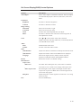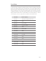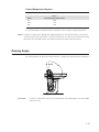
1
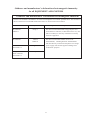
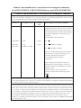
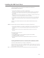
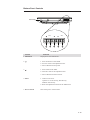
Touchmonitor User Guide
1519LM 15.6” LCD Desktop Touchmonitor
1919LM 18.5” LCD Desktop Touchmonitor
Elo TouchSystems
15.6” and 18.5” LCD Touchmonitor
User Guide
Revision A
SW601463
Elo TouchSystems
1-800-ELOTOUCH
www.elotouch.com
Copyright © 2010 Tyco Electronics. All Rights Reserved.
No part of this publication may be reproduced, transmitted, transcribed, stored in a retrieval
system, or translated into any language or computer language, in any form or by any means,
including, but not limited to, electronic, magnetic, optical, chemical, manual, or otherwise
without prior written permission of Tyco Electronics.
Disclaimer
The information in this document is subject to change without notice. Tyco Electronics makes
no representations or warranties with respect to the contents hereof, and specifically disclaims
any implied warranties of merchantability or fitness for a particular purpose. Tyco
Electronics reserves the right to revise this publication and to make changes from time to time
in the content hereof without obligation of Tyco Electronics to notify any person of such
revisions or changes.
Trademark Acknowledgments
AccuTouch, CarrollTouch, Elo TouchSystems, IntelliTouch, Tyco Electronics and TE (logo) are
trademarks of the Tyco Electronics group of companies and its licensors. Windows is a
trademark of the Microsoft group of companies. Other product names mentioned herein may be
trademarks or registered trademarks of their respective companies.Tyco Electronics claims no
interest in trademarks other than its own.
iii
Warnings and Cautions
!
Warning
• Danger - Explosion hazard. Do not use in the presence of flammable anesthetics, and other flammable materials.
• To prevent fire or shock hazards, do not immerse the unit in water or expose it to rain or moisture.
• Do not use the unit with an extension cord receptacle or other outlets unless the prongs of the power cord can be fully inserted.
• RISK OF ELECTRICAL SHOCK - DO NOT OPEN. To reduce the risk of electrical shock, DO NOT remove the back of the equipment or open the enclosure. No user-serviceable parts are inside. Refer servicing to qualified field service engineers only.
• Uninsulated voltage within the unit may have sufficient magnitude to cause electrical shock. Avoid contact with any part inside the unit.
• This device complies with all applicable electromagnetic emission and immunity standards for medical device equipment. This device is designed to not cause harmful interference, and to accept any interference received, including interference that may cause undesired
operation. The performance of this device is limited to the emission and immunity standards that have been applied. Other device which are not designed to withstand emission levels as specified in the medical device standards may be susceptible to interference from this device.
Subjecting the device to conditions beyond the rated performance capabilities may result in emissions in excess of the standard. If it is determined that this device produces
electromagnetic or other interference it must be disconnected from power until the cause of the problem has been determined and resolved. If it is determined that this device is
functioning improperly due to electromagnetic and other interference it must be
disconnected from power until the cause of the problem has been determined and resolved.
• Elo TouchSystems recommends that after its useful life (or after sustaining unrepairable damage), customers dispose of the touchmonitor and its power supply in an
environmentally sound manner. Acceptable methods include the reuse of parts or whole products and the recycling of products, components, and materials. Please consult and obey national state, and local laws and ordinances governing the safe disposal of electronic
equipment.
Note that the fluorescent lamps inside this product contain mercury and must be recycled or disposed of according to local, state, or national laws. For more information, contact the Electronic Industries Alliance at www.eiae.org.
This product consists of devices that may contain mercury, which must be recycled or disposed
of in accordance with local, state, or federal laws. (Within this system, the backlight lamps in
the monitor display contain mercury.)
iv
Caution
• Power cord is used as a disconnection device. To de-energize equipment, disconnect the power cord.
• This unit must follow the national requirement and local state laws to dispose unit.
• Before connecting the cables to your Elo touchmonitor, make sure all components are
powered OFF.
Only approved components complying with IEC60601-1 series can be connected to
ET1519/
1919LM in Patient Environment. The use of ACCESSORY equipment
not complying with the equivalent safety requirements of this equipment may lead
to a reduced safety of the
resulting system. Consideration relating to the choices of accessory equipment should include:· Use of accessory in the patient environment.· Evidence that the safety
certification of the accessory has been performed in accordance to the appropriate
IEC 60601-1 and/or IEC 60601-1-1 harmonized national standard.
• For continued safety - This unit only complies to the above standards if used with a medical grade power cord.
-A medical grade power supply, such as the one specified, is required for use in a medical application.
!
Note:
• This symbol alerts the user to important information concerning the operation and
maintenance of this unit, which should be read carefully to avoid problems.
• This symbol means DC Current.
• This symbol means ON/OFF stand-by switch.
v
Medical and Healthcare Application Disclaimer: If the Purchaser intends to commercialize, market or
use any product for medical or healthcare applications, it is the sole responsibility of the Purchaser to ensure that
the product is adequate and appropriate for the Purchaser’s intended use and complies with all applicable laws,
regulations, codes and standards including but not limited to the European Union Medical Device Directive, United
States Federal Food, Drug, and Cosmetic Act, regulations of the United States Food and Drug Administration (FDA),
and for obtaining and maintaining any required regulatory approvals including but not limited to any required market
clearances. Tyco Electronics has not sought nor received any rulings from the FDA or any other federal, state, or
local government agency or notified body as to the safety, effectiveness or appropriateness of its product for such
applications. Persons intending to evaluate or use Tyco Electronics’ product for medical or healthcare purposes must
rely on their own medical and legal judgment without any representation on the part of Tyco Electronics.
!
CAUTION-Life Support
Care must be taken when this touchmonitor is a critical component of a life support system or
device. In case of failure of this touchmonitor, appropriate redundant systems should be
incorporated into the system or device to prevent injury to the user or patient.
The following should be an integral part of the safety design of a life support system or device
using this touchmonitor for a critical function.
• An alternate interface or fail-safe must be available should the touchscreen fail to operate.
• The touchscreen interface must not be the only means of control of a critical function.
• An alternate video display should be incorporated into the safety design if used to monitor a critical function.
• The internal speakers of this touchscreen monitor must not be the sole method of warning of a critical function.
Critical functions are:
1. Life support devices or systems are devices or systems which, (a) are intended for
surgical implant into the body, or (b) support or sustain life, or (c) whose failure to perform when properly used in accordance with instructions for use provided in the labeling, can be reasonably expected to result in significant injury to the user.
2. A critical component is any component of a life support device or system whose failure to perform can be reasonably expected to cause the failure of the life support device or system, or to affect its safety or effectiveness.
Definitions:
“ PATIENT ENVIRONMENT”
any environment in which intentional or unintentional contact can occur between a PATIENT
and parts of the ME EQUIPMENT or ME SYSTEM or between a PATIENT and other persons
touching parts of the ME EQUIPMENT or ME SYSTEM.
vi
Classification
E342290
With respect to electrical shock, fire in accordance with UL60601-1 and CAN/CSA C22.2
No. 60601-1
This monitor is a Class I (GROUNDED) DEVICE.
These displays are classified NO APPLIED PARTS EQUIPMENT.
Protection against harmful ingress of water:
INGRESS PROTECTION (IPX0)
This monitor shall be classified as ORDINARY EQUIPMENT, not intended or evaluated for
use in the presence of flammable anesthetic mixture with air, oxygen, or nitrous oxide.
Mode of Operation: CONTINUOUS OPERATION.
Environmental conditions for transport and storage
Temp.
o
o
Operating
0 C to 40 C
o
o
Storage / Transportation -20 C to +60 C
Humidity (non-condensing)
Operating
30% to 70%
Storage / Transportation 10% to 90%
Altitude Operating Storage / Transportation
0 to 3,000m
0 to 40,000ft(12,192m)
Equivalent to 1013-303 hP.A
(14.7 to 4.4 psia)
For full Product Specifications refer to Appendix C
vii
European Standards and Classifications
Standards: EN 60601-1-2: 2007
The EMC limits and test methods are referred to the following standards:
Emission:
Immunity
CISPR 11: 2009+A1:2010
IEC 61000-4-2: 2008
IEC 61000-4-3: 2006+A1:2007+A2:2010
(Group 1, Class B)
IEC 61000-4-4: 2004 + A1:2010
IEC 61000-4-5: 2005
EN55011: 1998+A1: 1999+
IEC 61000-4-6: 2008
A2: 2002, (Group 1, Class B)
IEC 61000-4-8: 2009
IEC 61000-4-11: 2004
IEC 61000-3-2: 2005
IEC 61000-3-3; 2008
viii
Guidance and manufacturer’s declaration-electromagnetic immunityfor all EQUIPMENT AND SYSTEMS
Guidance and manufacturer’s declaration-electromagnetic emissions
The ET1519/1919LM is intended for use in the electromagnetic environment specified below. The customer or
the user of the ET1519/1919LM should assure that it is used in such an environment.
Emissions test
Compliance
Electromagnetic environment-guidelines
RF emissions
Group 1
CISPR 11
The ET1519/1919LM uses RF energy only for its in
ternal function. Therefore, its RF emissions are very low and are not likely to cause any interference in nearby
electronic equipment.
RF emissions
Class B
CISPR 11
Harmonics emissions
Not applicable
IEC 61000-3-2
Voltage fluctuations/
Complies
flicker emissions
IEC 61000-3-3
The ET1519/1919LM is suitabe for use in all establishments, including domestic establishments
and those directly connected to the public low-voltage
power supply network that supplies buildings used
for domestic purposes.
ix
Guidance and manufacturer’s declaration-electromagnetic immunityfor all EQUIPMENT AND SYSTEMS
Guidance and manufacturer’s declaration-electromagnetic immunity
The ET1519/1919LM is intended for use in the electromagnetic environment specified below. The customer or
the user of the ET1519/1919LM should assure that it is used in such an environment.
Immunity test
test level IEC 60601
Compliance level
Electromagnetic environment-
guidelines
Electrostatic
± 6 kV contact
± 6 kV contact
Floors should be wood, concrete or
discharge(ESD)
± 8 kV air
± 8 kV air
ceramic tile. If floors are covered with
IEC 61000-4-2
synthetic material, the relative humidity should be at least 30%.
Electrical Fast
± 2 kV for power
± 2 kV for power
Mains power quality should be that of a
transient/burst
supply lines
supply lines
typical commerical or hospital
environment.
IEC 61000-4-4
± 1 kV for input/output
± 1 kV for input/output
lines
lines
Surge
± 1 kV line(s) to line(s)
± 1 kV line(s) to line(s) Mains power quality should be that of a
IEC 61000-4-5
± 2 kV line(s) to earth
± 2 kV line(s) to earth
typical commerical or hospital
environment.
<5% UT
Voltage dips, short
<5% UT
interruption and
(>95% dip in U )
(>95% dip in U )
typical commerical or hospital
voltage variations
for 0.5 cycle
for 0.5 cycle
environment. If the user of the ET1519/
T
Mains power quality be that of a
T
on power supply
1919LM requires continued operation
40% UT
input lines
40% UT
(60% dip in U )
be powered from an uninterruptible
IEC 61000-4-11
for 5 cycles
for 5 cycles
power supply or a battery.
70% UT
70% UT
(30% dip in UT)
(30% dip in UT)
for 25 cycles
for 25 cycles
<5% UT
<5% UT
(>95% dip in UT)
(>95% dip in UT)
for 25 cycles
for 25 cycles
Power frequency
3 A/m
3A/m
T during power mains interruptions, it is
(60 % dip in U )
T recommended that the ET1519/1919LM
Power frequency magnetic fields
(50/60 Hz)
should be at levels characteristic of a
magnetic field
typical location in a typical commerical
or hospital environment.
IEC 61000-4-8
NOTE UT is the a.c. mains voltage prior to application of the test level.
x
Guidance and manufacturer’s declaration-electromagnetic immunityfor all EQUIPMENT AND SYSTEMS that are not LIFE-SUPPORTING
Guidance and manufacturer’s declaration-electromagnetic immunity
The ET1519/1919LM is intended for use in the electromagnetic environment specified below. The user of the
ET1519/1919LM should assure that it is used in such an environment.
Immunity test IEC 60601 test level Compliance level
Electromagnetic environment-guidelines
Conducted RF
d=1.2 P
3 Vrms
3 Vrms
Radiated RF
3 V/m
3 Vrms
IEC 61000-4-3 80 MHz to 2.5 GHz
Portable and mobile RF communications
equipment should be used no closer to any part of
the ET1519/1919LM, including cables, than the recommended separation distance calculated from
the equation applicable to the frequency of the transmitter.
Recommended separation distance
d=1.2 P 80MHz to 800 MHz
d=2.3 P 800 NHz to 2.5GHz
where P is the maximum output power rating of
the transmitter in watts (W) according to the
transmitter manufacturer and d is the
recommended separation distance
in metres(m)
Filed strengths from fixed RF transmitters, as
determined by an electromagnetic site survey 3, should be less than the compliance level in each
frequency range4.
Interference may occur in the vicinity of
equipment marked with the following symbol:
NOTE 1 At 80 MHz and 800 MHz, the higher frequency range applies.
NOTE 2 These guidelines may not apply in all situation. Electromagnetic propagation is affected by absorption
and reflection from structures, objects and people.
3.
Filed strengths from fixed transmitters, such as base stations for radio (cellular/cordless) telephones and land
mobile radios, amateur radio, AM and FM radio broadcast and TV broadcast cannot be predicted theoretically
with accuracy. To assess the electromagnetic environment due to fixed RF transmitters, an electromagnetic site
survey should be considered. If the measured filed strength in the location in which the ET1519/1919LM is
used exceeds the applicable RF compliance level above, the ET1519/1919LM should be observed to verify
normal operation. If abnormal performance is observed, additional measures may be necessary, such as
reorienting or relocating the ET1519/1919LM.4. Over the frequency range 150 kHz to 80 MHz, field strengths
should be less than 3 Vrms.
xi
Recommended separation distance between portable and mobile
RF communications equipment and the ET1519/1919LM
for all EQUIPMENT AND SYSTEMS that are not LIFE-SUPPORTING
Recommended separation distances between portable
and mobile RF communications equipment and the ET1519/1919LM
The ET1519/1919LM is intended for use in an electromagnetic environment in which radiated RF disturbances
are controlled. The customer or the user of the ET1519/1919LM can help prevent electromagnetic
interference by maintaining a minimum distance between portable and mobile RF communications (equipment)
and the ET1519/1919LM as recommended below according to the maximum output power of the
communications equipment.
Separation distance according to frequency of transmitter
Rated maximum output 150 kHz to 80 MHz
power of transmitter
W
d=1.2 P
80MHz to 800 MHz
800 MHz to 2.5 GHz
d=1.2 P
d=2.3 P
0.01
0.12
0.12
0.23
0.1
0.37
0.37
0.74
1
1.2
1.2
2.3
10
3.7
3.7
7.4
100
12
12
23
For transmitters rated at a maximum output power not listed above, the recommended separation distanced in
metres(m) can be estimated using the equation applicable to the frequency of the transmitter, where P is the
maximum output power rating of the transmitter in watts(W) according to the transmitter manufacturer.
NOTE 1 At 80 MHz and 800 MHz, the separation distance for the higher frequency range applies.
NOTE 2 These guidelines may not apply in all situations. Electromagnetic propagation is affected by
absorption and reflection from structures, objects and people.
xii
Table of Contents
Chapter 1 Introduction 1
Appendix B
Product Description........................................................................ 1 Precautions......................................................................................... 1
Care and Handling of Your Touchmonitor............................... 21
Chapter 2
Installation and Setup Touchmonitor Safety....................................................................... 20
Appendix C
Touchmonitor Specifications....................................................... 22
15.6" LCD Touchmonitor (ET1519LM) Dimensions.............. 25
18.5" LCD Touchmonitor (ET1919LM) Dimensions.............. 26
2
Unpacking Your Touchmonitor................................................... 2
Assembling the stand plate.......................................................... 4
Interface Connection ..................................................................... 5
Speakers and Audio......................................................................... 5
Product Overview............................................................................ 6
Main Unit..................................................................................... 6
Rear View..................................................................................... 6
Installing the Driver Software...................................................... 7
Installing the Serial Touch Driver (not applicable
to Acoustic Pulse Recognition monitor) ......................... 8
Installing the Serial Touch Driver for Windows 7,
Windows Vista, Windows XP, Windows 2000, ME,
Windows 95/98 and NT 4.0............................................ 9
Installing the Serial Touch Driver for MS-DOS
and Windows 3.1...................................................................... 9
Installing the USB Touch Driver........................................... 10
Installing the USB Touch Driver for Windows 7,
Windows Vista, Windows XP, Windows 2000, ME,
and Windows 98................................................................ 10
Installing APR USB Touch Driver for
Windows XP........................................................................ 10
Chapter 3
Operation Regulatory Information
Warranty
11
About Touchmonitor Adjustments............................................ 11
Bottom Panel Controls........................................................... 12
Controls and Adjustment.............................................................. 13
OSD Menu Functions.............................................................. 13
OSD Lock/Unlock...................................................................... 13
OSD Control Options.............................................................. 14
Preset Modes............................................................................. 15
Power Management System................................................ 16
Display Angle..................................................................................... 16
Chapter 4
Troubleshooting
17
Solutions to Common Problems................................................. 17
Appendix A
Native Resolution............................................................................. 18
v
27
30
CHAPTER
1
INTRODUCTION
Product Description
Your new 1519/1919LM touchmonitor combines the reliable performance of touch technology
with the latest advances in LCD display design. This combination of features creates a natural
flow of information between a user and your touchmonitor.
This LCD monitor incorporates a 15.6” or 18.5” color active matrix thin-film-transistor (TFT)
liquid crystal display to provide high quality display performance. A maximum resolution of
WXGA 1366 x 768 is well-suited for displaying both graphics and images. Other features that
enhance the performance of this LCD touchmonitor are Plug & Play compatibility, OSD (On
Screen Display) controls, and Elo’s unique zero-bezel Acoustic Pulse Recognition (APR), AT,
IT touchscreen. In addition, the 1519/1919LM is easily configurable for either portrait or
landscape orientation.
Precautions
Follow all warnings, precautions and maintenance procedure as recommended in this user’s
manual to maximize the life of the touch monitor. See Appendix B for more information on
touchmonitor safety.
1-1
CHAPTER
2
INSTALLATION AND SETUP
This chapter discusses how to install the 1519/1919LM LCD touchmonitor and the driver
software.
Unpacking Your Touchmonitor
Check that the following items are present and in good condition:
LCD monitor
VGA cable
USB cable
Audio cable
Elo QuickStart
CD
Software
CD and Quick Install Guide
Power Brick
Serial Cable
(not included with APR model)
DVI cable
2-2
Power cable for North America models
USA/UL Power cable
Power cable for European models
Europe/VDE power cable
UK power cable
Power cable for Japan models
Japanese/PSE power cable
Adapter/Terminal
2-3
Assembling the stand plate
Pushing the stand plate toward the stand untill it is tight, then fasten the stand plate using
captive screw.
2-4
Interface Connection
Note:
Before connecting the cables to your touchmonitor and PC, be sure that the computer and touchmonitor are turned off.
DVI Cable
Headphone Cable
1
2
2
3
Serial Cable
3
4
Audio Cable
VGA Cable
USB Cable
Power Brick
1.Connect DC cable of the power brick to the monitor and the other end through AC power cable to the AC outlet.
2.Connect one end of either the touchscreen serial (RS232) cable or the touch screen USB cable (but not both) to the rear side of the computer and the other end to the LCD monitor. Tighten by turning the two thumb screws clockwise to ensure proper grounding.
3.Connect one end of the VGA cable or DVI cable to the rear side of computer and the other to the LCD monitor. Tighten by turning the two thumb screws clockwise to ensure proper grounding.
4.Connect one end of the audio cable to the rear side of computer and the other to the LCD monitor.
5. Facing the monitor, press the power button located on the underside of the botom-right
corner of the monitor.
Speakers and Audio
The touchmonitor includes two built-in speakers. To use the speakers, plug in the audio cable
to the Audio Input port and connect the other end to your computer.
To use headphones, plug in the headphones to the Audio Output port shown above. When
headphones are connected, the sound plays through the headphones only.
The volume and muting of the sound can be adjusted by using the “Audio” choice from the
On-Screen Display (OSD) Control panel menu as described on page 3-14.
2-5
Product Overview
Main Unit
Rear View
TM
Kensington Lock
The KensingtonTM lock is a security device that prevents theft. To find out more about this
security device, go to http://www.kensington.com.
2-6
Installing the Driver Software
Elo TouchSystems provides driver software that allows your touchmonitor to work with your
computer. Drivers are located on the enclosed CD-ROM for the following operating systems:
• Windows 7
• Windows Vista
• Windows XP
• Windows 2000
• Windows Me
• Windows 98
• Windows 95
• Windows NT 4.0
• Windows 3.1
• MS-DOS
Additional drivers and driver information for other operating systems are available on the Elo
TouchSystems web site at www.elotouch.com.
The Elo touchmonitor is plug-and-play compliant. Information on the video capabilities of your
touchmonitor is sent to your video display adapter when Windows starts. If Windows detects
your touchmonitor, follow the instructions on the screen to install a generic plug-and-play
monitor.
Refer to the following appropriate section for driver installation instructions.
Depending upon whether you connected the serial communication cable or the USB
communication cable, only the serial driver or the USB driver should be installed.
2-7
Installing the Serial Touch Driver (not applicable to Acoustic
Pulse Recognition monitor)
Installing the Serial Touch Driver for Windows 7, Windows Vista,
Windows XP, Windows 2000, ME, 95/98 and NT4.0.
NOTE: For Windows 2000 and NT4.0 you must have administrator access rights to install the driver. Make sure the serial connector (RS232) is plugged into the monitor and an open com port on the PC.
1 Insert the Elo CD-ROM in your computer's CD-ROM drive.
2 If the AutoStart feature for your CD-ROM drive is active, the system automatically detects the CD and starts the setup program.
3 Follow the directions on the screen to complete the driver setup for your version of
Windows.
4 If the AutoStart feature is not active:
5 Click Start > Run.
6 Click the Browse button to locate the EloCd.exe program on the CD-ROM.
7 Click Open, then OK to run EloCd.exe.
8 Follow the directions on the screen to complete the driver setup for your version of
Windows.
2-8
Installing the Serial Touch Driver for MS-DOS and Windows 3.1
You must have a DOS mouse driver (MOUSE.COM) installed for your mouse if you wish to
continue using your mouse along with your touchmonitor in DOS.
To install Windows 3.x and MS-DOS touch driver from Windows 95/98, follow the directions
below:
1 Insert the CD-ROM in your computer’s CD-ROM drive.
2 From DOS, type d: and press the Enter key to select the CD-ROM (your CD-ROM drive may be mapped to a different drive letter).
3 Type cd\elodos_w31 to change to the correct directory.
4 Type Install and press Enter to start the installation.
5 Calculate the touchscreen.
2-9
Installing the USB Touch Driver
Installing the USB Touch Driver for Windows 7, Windows Vista, Windows XP,
Windows 2000, ME and Windows 98.
1 Insert the Elo CD-ROM in your computer’s CD-ROM drive.
If Windows 98 or Windows 2000 starts the Add New Hardware Wizard, do the following:
2 Choose Next. Select “Search for the best driver for your device (Recommended)” and choose Next.
3 When a list of search locations is displayed, place a checkmark on “Specify a location” and use Browse to select the \EloUSB directory on the Elo CD-ROM.
4 Choose Next. Once the Elo USB touchscreen driver has been detected, choose Next again.
5 You will see several files being copied. Insert your Windows 98 cd if prompted. Choose
Finish.
If Windows 98 or Windows 2000 does not start the Add New Hardware Wizard, do the
following:
NOTE: For Windows 2000 you must have administrator access rights to install the driver.
1 Insert the Elo CD-ROM in your computer’s CD-ROM drive. If the AutoStart feature for your
CD-ROM drive is active, the system automatically detects the CD and starts the setup
program.
2 Follow the directions on the screen to complete the driver setup for your version of
Windows.
If the AutoStart feature is not active:
1 Click Start > Run.
2 Click the Browse button to locate the EloCd.exe program on the CD-ROM.
3 Click Open, then OK to run EloCd.exe.
4 Follow the directions on the screen to complete the driver setup for your version of
Windows.
Installing APR USB Touch Driver for Windows XP and Windows VISTA
Insert the Elo APR CD-ROM in your computer’s CD-ROM driver.
Follow the directions on the screen to complete the APR 3.1 driver setup for your version of
Windows. Do not plug USB cable until software is fully loaded. When finished, plug USB
cable and alignment data is transferred.
Note: For the latest driver, go to elotouch.com and download it from the driver download section.
2-10
CHAPTER
3
OPERATION
About Touchmonitor Adjustments
Your touchmonitor will not likely require adjustment. However, variations in video output and
application may require adjustments to the touchmonitor to optimize the quality of the display.
For best performance, the input video resolution should be the touchmonitors native resolution,
1366 x 768. Use the Display control panel in Windows to choose 1366 x 768 resolution.
Operating in other resolutions will degrade video performance. For further information, please
refer to Appendix A.
All adjustments made to the controls are automatically memorized. This feature saves you from
having to reset the choices every time the touchmonitor is unplugged or powered off and on. If
there is a power failure, the touchmonitor settings will not default to the factory specifications.
3-11
Bottom Panel Controls
SELECT
MENU
Audio Output
SELECT
5
4
MENU
3
2
1
Control
1 Menu/Exit
Function
Display/Exits the OSD menus.
2 1. Enter Luminance of the OSD.
2. Increase value of the adjustment item.
3. Move OSD selection upward.
3
1. Enter Audio of the OSD.
2. Decrease value of the adjustment item.
3. Move OSD selection downward .
4 Select
1. Video source select.
Options are: VGA Priority, DVI Priority.
Default: DVI Priority
2. Select the adjustment item from the OSD menu.
5 Power Switch Switch the power of the monitor.
3-12
Controls and Adjustment
On Screen Display (OSD) Menu Functions
To Display and Select the OSD Functions:
1.Press the Menu key to activate the OSD menu.
2.Use
or
to move upward or downward through the menu. Press the “Select” key,
execute the function or enter the sub-menu.
3.To quit the OSD screen at any time during the operation, press the Menu key. If no keys are pressed for a short time period, the OSD automatically disappears.
NOTE: The OSD screen will disappear if no input activities are detected for at a minimum of 15 seconds or depending on how long the timer is set via the OSD menu. The time ranges from 5 seconds to 60 seconds.
On Screen Display (OSD) Lock/Unlock
The OSD feature can be locked and unlocked. The monitor is shipped in the unlocked position.
To lock the OSD:
1. Press the Menu button and
button simultaneously until a window appears displaying “OSD Unlocked”. Continue to hold the buttons until the window toggles to “OSD Locked”.
2. To unlock the the Power Locking Feature, repeat the procedure until the “OSD Unlocked” is displayed.
To lock the power:
1. Press the menu and
button simultaneously until a window displaying “Power unlocked” appears. Continue to hold the buttons until the “Power Locked”.
2. To unlock the power repeat the procedure until the “Power Unlocked” is displayed.
3-13
On Screen Display(OSD) Control Options
Control Auto-Adjust Luminance
.Brightness .Contrast Image Setting
.H-Position .V-Position .Clock
.Phase
Description
Select “Auto-Adjust” to enable this function. The Auto-Adjust will automatically adjust V-Position, H-Position, Clock and Phase.
Color Audio
.Mute
.Volume
Press or to select 9300, 6500, 5500, 7500 and USER. Only when selecting USER can you make adjustments to the R/G/B content values.
OSD
.OSD Rotation .OSD Timeout
.Language Recall Miscellaneous
.Aspect ratio
..Fill screen
..Fill to Aspect ratio
.Sharpness
Exit
Increases or decreases brightness
Increases or decreases contrast
Moves the screen left or right
Moves the screen up or down
The dot clock is fine-adjusted after auto adjust.
Increases or decreases the video noise of the image after an auto adjustment is made.
Enable/Disable audio mute.
Increase or decrease audio volume.
Adjusts the direction of OSD for Landscape and Portrait mode.
Adjusts the amount of time of the OSD menu is displayed.
Select from English, French, Italian, German, Spanish,
Japanese, Traditional Chinese and Simplified Chinese.
Returns the monitor to its default settings.
No matter what LCD aspect ratio, scales video so it fills the LCD with no over or under scan. Change video aspect ratio.
Sets the height of video equal to the height of LCD. Video
Aspect ratio is preserved. Black bars on left and right side of LCD screen may appear.
Adjusts sharpness of video signals on a scale from 1 to 5 using 4 discrete steps.
Exits the OSD display.
3-14
Preset Modes
To reduce the need for adjustment for different modes, the monitor has default setting modes
that are most commonly used as given in the table below. If any of these display modes are
detected, the monitor automatically adjusts the picture size and centering. When none of the
modes are matched, the user can store their preferred modes in the user modes. The monitor
is capable of storing up to 7 user modes. The only condition to store as a user mode is the new
display information which must have 1 KHz difference for horizontal frequency or 1 Hz for
vertical frequency or the sync signal polarities are different from the default modes.
Resolution
Vertical Frequency 720 x 350 70Hz (may not display at full screen)
720 x 400 70Hz
640 x 480 60 / 72 / 75Hz
800 x 600 56 / 60 / 72 / 75Hz
832 x 624
75Hz
1024 x 768
60 / 70 / 75Hz
1280 x 800
60Hz
1280 x 960 60Hz
1280 x 1024 60 / 75Hz
1360 x 768 60Hz
1366 x 768
60Hz
1440 x 900
60Hz
1600 x 1200 60Hz
1680 x 1050 60Hz
3-15
Power Management System
Mode
On Sleep Off Power
Consumption (12VDC input)
<42W
<4W
<2W
It is recommended to switch the monitor off when it is not in use for a long period of time.
NOTE: Complies to VESA Power Management (DPM) standards. To activate the monitor, press any key on the keyboard or move the mouse or touch the touchscreen. In order for the touchscreen to bring the monitor from the DPM system, the touchscreen function must be fully operational.
Display Angle
For viewing clarity, the LCD can tilt forward (up to -5 degrees) or backward (up to 90 degrees.)
CAUTION
In order to protect the LCD, be sure to hold the base when adjusting the LCD and do not touch the screen.
3-16
CHAPTER
4
TROUBLESHOOTING
If you are experiencing trouble with your touchmonitor, refer to the following table. If the
problem persists, please contact your local dealer or the Elo service center.
Solutions to Common Problems
Problem
Suggestion(s)
The monitor does not respond 1.Check that the monitor’s Power Switch is on.
when turning on the system. 2.Turn off the power and check the monitor’s DC power cord
and signal cable for proper connection.
Characters on the screen are dim
Refer to the About Touchmonitor Adjustments section to
adjust the brightness.
The video is blank
1.During operation, the monitor screen may automatically turn off as a result of the Power Saving feature. Press any key to see if the screen reappears.
2.Refer to the About Touchmonitor Adjustments section to adjust the brightness.
Screen flashes when initialized
Turn the monitor off then turn it on again.
“Out of Range” display
Reconfigure the resolution of your computer to make one of the monitor’s supported video mode (see Appendix C).See Appendix A
for more information on resolution.
Touch doesn’t work
Make sure the touch cable is securely attached at both ends.
4-17
APPENDIX
A
NATIVE RESOLUTION
The native resolution of a monitor is the resolution level at which the LCD panel is designed to
perform best. For the LCD touchmonitor, the native resolution is 1366 x 768 for the 15.6 inch
and 18.5 inch size. In almost all cases, screen images look best when viewed at their native
resolution. The resolution setting of a monitor can be lowered but not increased.
Input Video 1519LM/1919LM monitor
640 x 480 (VGA) Transforms input format to 1366 x 768
800 x 600 (SVGA) Transforms input format to 1366 x 768
1024 x 768 (SVGA) Transforms input format to 1366 x 768
1366 x 768 (WXGA) Displays in Native Resolution
1360 x 768
Displays with scaling
The native resolution of an LCD is the actual number of pixels horizontally in the LCD by the
number of pixels vertically in the LCD. LCD resolution is usually represented by the following
symbols:
VGA SVGA
XGA
SXGA
UXGA
WXGA, avg
SXGA-
WXGA, max
WXGA+
WSXGA+
640 x 480
800 x 600
1024 x 768
1280 x 1024
1600 x 1200
1280 x 800
1280 x 960
1366 x 768
1440 x 900
1680 x 1050
A-18
As an example, a SVGA resolution LCD panel has 800 pixels horizontally by 600 pixels
vertically. Input video is also represented by the same terms. XGA input video has a format of
1024 pixels horizontally by 768 pixels vertically. When the input pixels contained in the video
input format match the native resolution of the panel, there is a one to one correspondence of
mapping of input video pixels to LCD pixels. As an example, the pixel in column 45 and row
26 of the input video is in column 45 and row 26 of the LCD. For the case when the input
video is at a lower resolution than the native resolution of the LCD, the direct correspondence
between the video pixels and the LCD pixels is lost. The LCD controller can compute the
correspondence between video pixels and LCD pixels using algorithms contained on its
controller. The accuracy of the algorithms determines the fidelity of conversion of video pixels
to LCD pixels. Poor fidelity conversion can result in artifacts in the LCD displayed image such
as varying width characters.
A-19
APPENDIX
B
TOUCHMONITOR SAFETY
This manual contains information that is important for the proper setup and maintenance of
your touchmonitor. Before setting up and powering on your new touchmonitor, read through
this manual, especially Chapter 2 (Installation), and Chapter 3 (Operation).
1 To reduce the risk of electric shock, follow all safety notices and never open the
touchmonitor case.
2 Turn off the product before cleaning.
3 The slots located on the sides and top of the touchmonitor case are for ventilation. Do not block or insert anything inside the ventilation slots.
4 It is important that your touchmonitor remains dry. Do not pour liquid into or onto your touchmonitor. If your touchmonitor becomes wet do not attempt to repair it yourself.
B-20
Care and Handling of Your Touchmonitor
The following tips will help keep your touchmonitor functioning at the optimal level.
• To avoid risk of electric shock, do not disassemble the brick power supply or display unit cabinet. The unit is not user serviceable. Remember to unplug the display unit from the
power outlet before cleaning.
• Do not use alcohol (methyl, ethyl or isopropyl) or any strong dissolvent. Do not use thinner or benzene, abrasive cleaners or compressed air.
• To clean the display unit cabinet, use a cloth lightly dampened with a mild detergent.
• Avoid getting liquids inside your touchmonitor. If liquid does get inside, have a qualified
service technician check it before you power it on again.
• Do not wipe the screen with a cloth or sponge that could scratch the surface.
• To clean the touchscreen, use window or glass cleaner. Put the cleaner on a clean cloth and wipe the touchscreen. Never apply the cleaner directly to the touchscreen.
Warning
This product consists of devices that may contain mercury, which must be recycled or disposed
of in accordance with local, state, or federal laws. (Within this system, the backlight lamps in
the monitor display contain mercury.)
Waste Electrical and Electronic Equipment (WEEE) Directive
In the European Union, this label indicates that this product should not be disposed of with
household waste. It should be deposited at an appropriate facility to enable recovery and
recycling.
B-21
APPENDIX
C
TECHNICAL SPECIFICATIONS
C-22
Touchmonitor Specifications
Model LCD Display Display Size Pixel Pitch Native Resolution
Display Mode Contrast Ratio Brightness Response Time Display Color Viewing Angle Input Video
Signal Type
Sync
Connector Bottom Controls Speakers
Audio Input Connector
Headphone Output connector
OSD Plug & Play Touch Panel
Power Adapter Operating Conditions Temperature
Humidity
Altitude Storage Conditions
Temperature
Humidity Altitude
Dimensions (HxWxD) Weight (Net) Certifications 1919LM
18.5” TFT Active Matrix Panel
409.8 (H) x 230.4 (V) mm
0.3 (H) x 0.3 (V) mm
1366 x 768
720 x 350 (70Hz) - (may not display at full screen)
720 x 400 (70Hz)
640 x 480 (60 / 72 / 75Hz)
800 x 600 (56 / 60 / 72 / 75Hz)
832 x 624 (75Hz)
1024 x 768 (60 / 70 / 75Hz)
1280 x 800 (60Hz)
1280 x 960 (60Hz)
1280 x 1024 (60 / 75Hz)
1360 x 768 (60Hz)
1366 x 768 (60Hz)
1440 x 900 (60Hz)
1600 x 1200 (60Hz)
1680 x 1050 (60Hz)
1000 : 1 (typical)
LCD Monitor: typical 300 Cd/m2 ; Min 240 Cd/m2
AccuTouch: typical 240 Cd/m2 ; Min 180 Cd/m2
IntelliTouch: typical 270 Cd/m2 ; Min 204 Cd/m2
Acoustic Pulse Recognition: typical 270 Cd/m2 ; Min 204 Cd/m2
Tr+Tf =5ms (Typ.)
16.7M
o
Vertical ±80
o
Horizontal ±85
R.G.B. Analog 0.7Vp-p, 75 ohm
TTL Positive or Negative, Sync on green or Composite Sync.
Mini D-Sub 15 pin ; DVI-D
Menu,
,
, Select, Power
Two 2W internal speakers
3.5mm TRS jack
Two 3.5m TRS jack Contrast, Brightness, H-Position, V-Position,
Color Temperature, Phase, Clock, OSD Time, Recall,
Language: English, French, Italian, German, Spanish, Japanese,
Traditional Chinese and Simplified Chinese
DDC 2B
AccuTouch /IntelliTouch/Acustic Pulse Recognition
Input: AC 100-240V, 50-60Hz , Output: DC 12V/4A
o
o
0 C ~ 40 C
20% ~ 80% (No Condensation)
0 to 3,000m
o
o
-20 C ~ 50 C
10% ~ 90% (No Condensation)
0 to 12,192m
453.92 x 321.02 x 236.2mm
7.3Kg
CUL, UL, CE, FCC, VCCI, ICES-003
C-23
Touchmonitor Specifications
Model LCD Display Display Size Pixel Pitch Native Resolution
Display Mode Contrast Ratio Brightness Response Time Display Color Viewing Angle Input Video
Signal Type
Sync
Connector Bottom Controls Speakers
Audio Input Connector
Headphone Output connector
OSD Plug & Play Touch Panel
Power Adapter Operating Conditions Temperature
Humidity
Altitude Storage Conditions
Temperature
Humidity Altitude
Dimensions (HxWxD) Weight (Net) Certifications 1519LM
15.6” TFT Active Matrix Panel
344.232 (H) x 193.536 (V) mm
0.252 (H) x 0.252 (V) mm
1366 x 768
720 x 350 (70Hz) - (may not display at full screen)
720 x 400 (70Hz)
640 x 480 (60 / 72 / 75Hz)
800 x 600 (56 / 60 / 72 / 75Hz)
832 x 624 (75Hz)
1024 x 768 (60 / 70 / 75Hz)
1280 x 800 (60Hz)
1280 x 960 (60Hz)
1280 x 1024 (60 / 75Hz)
1360 x 768 (60Hz)
1366 x 768 (60Hz)
1440 x 900 (60Hz)
1600 x 1200 (60Hz)
1680 x 1050 (60Hz)
500 : 1 (typical)
LCD Monitor: typical 250 Cd/m2 ; Min 210 Cd/m2
AccuTouch: typical 200 Cd/m2 ; Min 157.5 Cd/m2
IntelliTouch: typical 225 Cd/m2 ; Min 178.5 Cd/m2
Tr+Tf =8ms (Typ.)
16.7M
o
o
Vertical -45 /+20
o
Horizontal ±45
R.G.B. Analog 0.7Vp-p, 75 ohm
TTL Positive or Negative, Sync on green or Composite Sync.
Mini D-Sub 15 pin; DVI-D
Menu,
,
, Select, Power
Two 2W internal speakers
3.5mm TRS jack
Two 3.5m TRS jack
Contrast, Brightness, H-Position, V-Position,
Color Temperature, Phase, Clock, OSD Time, Recall,
Language: English, French, Italian, German, Spanish, Japanese,
Traditional Chinese and Simplified Chinese
DDC 2B
AccuTouch /IntelliTouch
Input: AC 100-240V, 50-60Hz , Output: DC 12V/4A
o
o
0 C ~ 40 C
20% ~ 80% (No Condensation)
0 to 3,000m
o
o
-20 C ~ 50 C
10% ~ 90% (No Condensation)
0 to 12,192m
383.05 x 276.5 x 213.2mm
5.2Kg
CUL, UL, CE, FCC, VCCI, ICES-003
C-24
15” LCD Touchmonitor (1519LM) Dimensions
C-25
19” LCD Touchmonitor (1919LM) Dimensions
26
REGULATORY INFORMATION
I. Electrical Safety Information:
A) Compliance is required with respect to the voltage, frequency, and current requirements indicated on the manufacturer’s label. Connection to a different power source than those
specified herein will likely result in improper operation, damage to the equipment or pose a fire hazard if the limitations are not followed.
B) There are no operator serviceable parts inside this equipment. There are hazardous
voltages generated by this equipment which constitute a safety hazard. Service should be provided only by a qualified service technician.
C) Contact a qualified electrician or the manufacturer if there are questions about the installation prior to connecting the equipment to mains power.
II. Emissions and Immunity Information
A) Notice to Users in the United States: This equipment has been tested and found to
comply with the limits for a Class B digital device, pursuant to Part 15 of FCC Rules. These limits are designed to provide reasonable protection against harmful interference in
a residential installation. This equipment generates, uses, and can radiate radio frequency energy, and if not installed and used in accordance with the instructions, may cause
harmful interference to radio communications.
B) Notice to Users in Canada: This equipment complies with the Class B limits for radio noise emissions from digital apparatus as established by the Radio Interference
Regulations of Industrie Canada.
C) Notice to Users in the European Union: Use only the provided power cords and
interconnecting cabling provided with the equipment. Substitution of provided cords and
cabling may compromise electrical safety or CE Mark Certification for emissions or
immunity as required by the following standards:
This Electronic Equipment is required to have a CE Mark on the manufacturer’s label which means that the equipment has been tested to the follwing Directives and Standards: This equipment has been tested to the requirements for the CE Mark as
required by 2004/108/EC EMC and LVD 2006/95/EC indicated in European Standard
EN 60601-1 and EN60601-1-2 (including EN55011 Class B)
27
D) General Information to all Users: This equipment generates, uses and can radiate radio
frequency energy. If not installed and used according to this manual the equipment may cause interference with radio and television communications. There is, however, no
guarantee that interference will not occur in any particular installation due to site-specific factors.
1) In order to meet emission and immunity requirements, the user must observe the following:
a) Use only the provided I/O cables to connect this digital device with any computer.
b)To ensure compliance, use only the provided manufacturer’s approved line cord.
c)The user is cautioned that changes or modifications to the equipment not
expressly approved by the party responsible for compliance could void the user’s authority to operate the equipment.
2) If this equipment appears to cause interference with radio or television reception, or any other device:
a) Verify as an emission source by turning the equipment off and on.
b) If you determine that this equipment is causing the interference, try to
correct the interference by using one or more of the following measures:
i) Move the digital device away from the affected receiver.
ii)Reposition (turn) the digital device with respect to the affected receiver.
iii) Plug the digital device into a different AC outlet so the digital device and the receiver are on different branch circuits.
iv) Disconnect and remove any I/O cables that the digital device does not use. (Unterminated I/O cables are a potential source of high RF
emission levels.)
v) Plug the digital device into only a grounded outlet receptacle. Do not use AC adapter plugs. (Removing or cutting the line cord ground may increase RF emission levels and may also present a lethal shock
hazard to the user.)
If you need additional help, consult your dealer, manufacturer, or an experienced radio or television technician.
28
III. Agency Certifications
The following certifications have been issued for this monitor:
•
•
•
•
•
•
Canada CUL
Canada IC
Europe CE
Japan VCCI
FCC
United States UL
29
WARRANTY
Except as otherwise stated herein or in an order acknowledgment delivered to Buyer, Seller
warrants to Buyer that the Product shall be free of defects in materials and workmanship. The
warranty for the touchmonitors and components of the product is 3 (three) years.
Seller makes no warranty regarding the model life of components. Seller’s suppliers may at any
time and from time to time make changes in the components delivered as Products or
components.
Buyer shall notify Seller in writing promptly (and in no case later than thirty (30) days after
discovery) of the failure of any Product to conform to the warranty set forth above; shall
describe in commercially reasonable detail in such notice the symptoms associated with such
failure; and shall provide to Seller the opportunity to inspect such Products as installed, if
possible. The notice must be received by Seller during the Warranty Period for such product,
unless otherwise directed in writing by the Seller. Within thirty (30) days after submitting such
notice, Buyer shall package the allegedly defective Product in its original shipping carton(s) or
a functional equivalent and shall ship to Seller at Buyer’s expense and risk.
Within a reasonable time after receipt of the allegedly defective Product and verification by
Seller that the Product fails to meet the warranty set forth above, Seller shall correct such
failure by, at Seller’s options, either (i) modifying or repairing the Product or (ii) replacing the
Product. Such modification, repair, or replacement and the return shipment of the Product with
minimum insurance to Buyer shall be at Seller’s expense. Buyer shall bear the risk of loss or
damage in transit, and may insure the Product. Buyer shall reimburse Seller for
transportation cost incurred for Product returned but not found by Seller to be defective.
Modification or repair, of Products may, at Seller’s option, take place either at Seller’s facilities
or at Buyer’s premises. If Seller is unable to modify, repair, or replace a Product to conform
to the warranty set forth above, then Seller shall, at Seller’s option, either refund to Buyer or
credit to Buyer’s account the purchase price of the Product less depreciation calculated on a
straight-line basis over Seller’s stated Warranty Period.
30
THESE REMEDIES SHALL BE THE BUYER’S EXCLUSIVE REMEDIES FOR BREACH
OF WARRANTY. EXCEPT FOR THE EXPRESS WARRANTY SET FORTH ABOVE,
SELLER GRANTS NO OTHER WARRANTIES, EXPRESS OR IMPLIED BY STATUTE OR
OTHERWISE, REGARDING THE PRODUCTS, THEIR FITNESS FOR ANY PURPOSE,
THEIR QUALITY, THEIR MERCHANTABILITY, THEIR NONINFRINGEMENT, OR
OTHERWISE. NO EMPLOYEE OF SELLER OR ANY OTHER PARTY IS AUTHORIZED
TO MAKE ANY WARRANTY FOR THE GOODS OTHER THAN THE WARRANTY SET
FORTH HEREIN. SELLER’S LIABILITY UNDER THE WARRANTY SHALL BE
LIMITED TO A REFUND OF THE PURCHASE PRICE OF THE PRODUCT. IN NO EVENT
SHALL SELLER BE LIABLE FOR THE COST OF PROCUREMENT OR INSTALLATION
OF SUBSTITUTE GOODS BY BUYER OR FOR ANY SPECIAL, CONSEQUENTIAL,
INDIRECT, OR INCIDENTAL DAMAGES.
Buyer assumes the risk and agrees to indemnify Seller against and hold Seller harmless from
all liability relating to (i) assessing the suitability for Buyer’s intended use of the Products and
of any system design or drawing and (ii) determining the compliance of Buyer’s use of the
Products with applicable laws, regulations, codes, and standards. Buyer retains and accepts full
responsibility for all warranty and other claims relating to or arising from Buyer’s products,
which include or incorporate Products or components manufactured or supplied by Seller.
Buyer is solely responsible for any and all representations and warranties regarding the
Products made or authorized by Buyer. Buyer will indemnify Seller and hold Seller harmless
from any liability, claims, loss, cost, or expenses (including reasonable attorney’s fees)
attributable to Buyer’s products or representations or warranties concerning same.
31
Check out Elo’s Website!
www.elotouch.com
Get the latest...
• Product information
• Specifications
• News on upcoming events
• Press release
• Software drivers
• Touchmonitor Newsletter
Getting in Touch with Elo
To find out more about Elo’s extensive range of touch solutions, visit our Website at www.elotouch.com or simply call the office
nearest you:
Germany
Belgium
Asian-Pacific
Elo TouchSystems
301 Constitution Drive,
Menlo Park, CA 94025
USA
(800) ELO-TOUCH
(800-557-1458)
Tel 650-361-4800
Fax 650-361-4722
[email protected]
Tyco Electronics Raychem GmbH
(Elo TouchSystems Division)
Finsinger Feld 1
D-85521 Ottobrunn
Germany
Tyco Electronics Raychem GmbH
(Elo TouchSystems Division)
Diestsesteenweg 692
B-3010 Kessel-Lo
Belgium
Sun Homada Bldg. 2F
1-19-20 Shin-Yokohama
Kanagawa 222-0033
Japan
Tel +49(0)(89)60822-0
Fax +49(0)(89)60822-180
[email protected]
Tel +32(0)(16)35-2100
Fax +32(o)(16)35-2101
[email protected]
Tel +81(45)478-2161
Fax +81(45)478-2180
www.tps.co.jp
© 2010 Tyco Electronics. Printed in USA
North America