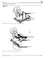
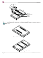
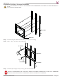
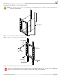
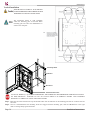
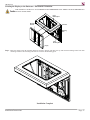
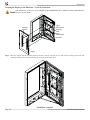
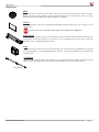
1
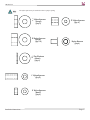
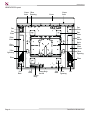
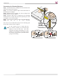
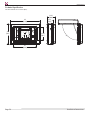
INSTALLATION INSTRUCTIONS
GB-ENCL2
Universal Enclosure
NORTH AMERICA
3130 East Miraloma Avenue
Anaheim, CA 92806 USA
USA and Canada –
Phone: 800-368-9700
Fax: 800-832-4888
Other Locations – Phone: (001)-714-632-7100; Fax: (001)-714-632-1044
©Premier Mounts 2010
9534-00-00-0
EUROPE
Swallow House,
Shilton Industrial Estate,
Shilton, Coventry, England CV79JY
Phone: +44 (0) 2476 614700
Fax: +44 (0) 2476 614710
GB-ENCL2
Table of Contents
Warning Statements
Parts List
Installation Tools
GB-ENCL2 Layout
Thread Depth Indicator
Determining the Center of the Display
Positioning the Mounting Brackets
Securing the Mounting Brackets
Marking the Wall
Securing the Wall Plate - Horizontal Orientation
Horizontal Installation
Securing the Wall Plate - Vertical Installation
Vertical Installation
Securing the Display to the Enclosure - Horizontal Orientation
Securing the Display to the Enclosure - Vertical Orientation
Maintenance
Technical Specifications
Warranty
2
3
3
6
7
8
9
11
12
13
14
15
16
17
18
19
20
21
Warning Statements
PRIOR TO THE INSTALLATION OF THIS PRODUCT, THE INSTALLATION INSTRUCTIONS SHOULD BE READ AND COMPLETELY UNDERSTOOD. THE INSTALLATION INSTRUCTIONS MUST BE READ TO PREVENT PERSONAL INJURY AND
PROPERTY DAMAGE. KEEP THESE INSTALLATION INSTRUCTIONS IN AN EASILY ACCESSIBLE LOCATION FOR FUTURE
REFERENCE.
PREMIER MOUNTS DOES NOT WARRANT AGAINST DAMAGE CAUSED BY THE USE OF ANY PREMIER MOUNTS PRODUCT
FOR PURPOSES OTHER THAN THOSE FOR WHICH IT WAS DESIGNED OR DAMAGE CAUSED BY UNAUTHORIZED ATTACHMENTS OR MODIFICATIONS, AND IS NOT RESPONSIBLE FOR ANY DAMAGES, CLAIMS, DEMANDS, SUITS, ACTIONS OR
CAUSES OF ACTION OF WHATEVER KIND RESULTING FROM, ARISING OUT OF OR IN ANY MANNER RELATING TO ANY
SUCH USE, ATTACHMENTS OR MODIFICATIONS.
THE WALL STRUCTURE MUST BE CAPABLE OF SUPPORTING 160 LBS. IF NOT, THE WALL STRUCTURE MUST BE REINFORCED. PROPER INSTALLATION PROCEDURE BY A QUALIFIED SERVICE TECHNICIAN, AS OUTLINED IN THE INSTALLATION INSTRUCTIONS, MUST BE ADHERED TO. FAILURE TO DO SO COULD RESULT IN SERIOUS PERSONAL INJURY, OR
EVEN DEATH.
SAFETY MEASURES MUST BE PRACTICED AT ALL TIMES DURING THE INSTALLATION OF THIS PRODUCT. USE PROPER
SAFETY GEAR AND TOOLS FOR THE INSTALLATION PROCEDURE TO PREVENT PERSONAL INJURY.
Indicates that the power plug is to be disconnected
from the power outlet.
Contact Premier Mounts with any questions (800) 368-9700.
Safety precautions must be taken at all times.
Warning and Caution statements.
It is recommended that a maximum of 5/8” plaster board be used when mounting to wooden studs.
Do not install on a structure that is prone to vibration, movement or chance of impact. Failure to do so could result in damage to the flat panel
display and/or damage to the mounting surface.
Do not install near heater, fireplace, direct sunlight, air conditioning or any other source of direct heat energy. Failure to do so may result in
damage to the flat panel display and could increase the risk of fire.
At least two qualified people should perform the installation procedure. Injury and/or damage can result from dropping or mishandling the
flat panel display.
Page 2
Installation Instructions
GB-ENCL2
Parts List
This enclosure is shipped with all proper installation hardware and components. Make sure that none of these parts
are missing and/or damaged before beginning installation. If there are parts missing and/or damaged, please stop the
installation and contact Premier Mounts (800-368-9700).
Wall Plate (Qty 1)
GB-ENCL2 (Qty 1)
Mounting Brackets (Qty 2)
5/16” x 3” Lag Bolts - wooden studs only (Qty 6)
2-1/2” Quick Release Pins (Qty 4)
Griplate™ (Qty 8)
5/16” Flat Washers (Qty 6)
Installation Tools
Soft Material/Blanket
Pencil
Tape Measure
Installation Instructions
1/2” Socket and Wrench
Phillips Head Screw Driver
Drill Gun
Thread Depth Indicator (Supplied)
Page 3
GB-ENCL2
M4 x 16
M4 x 25
M5 x 12
M5 x 16
M5 x 20
(Qty 8)
M6 x 20
(Qty 6)
M8 x 20
(Qty 6)
(Qty 4)
(Qty 8)
(Qty 6)
M8 x 25
(Qty 6)
M8 x 30
M5 x 25
Page 4
(Qty 6)
(Qty 4)
M5 x 50
M6 x 12
(Qty 6)
(Qty 4)
M8 x 35
(Qty 8)
M8 x 70
(Qty 4)
(Qty 4)
Installation Instructions
GB-ENCL2
The nylon spacers may be stacked to achieve proper spacing.
1
4"
1
2"
5
16"
Nylon Spacers
(Large)
(Qty 6)
Nylon Spacers
(Large)
(Qty 12)
9
16"
Nylon Spacers
(Qty 6)
Nylon Sleeves
(Qty 4)
Flat Washers
(Metal)
(Qty 6)
1" Nylon Spacers
(Qty 6)
1
4"
Installation Instructions
Nylon Spacers
(Small)
(Qty 6)
Page 5
GB-ENCL2
GB-ENCL2 Layout
Cover J-Box
Lock Opening
Cover
Lock
Cover
Fan
Fan
Plate
Fan
Plate
Fan
Plate
Filter
Cover
Gas
Shock
Gas
Shock
Back
Plate
Filter
Cover
J-Box
Opening
J-Box
Opening
Filter
Filter
Fan
Plate
Fan
Plate
Power
Strip
Page 6
Power Strip
On/Off
Fan
Plate
J-Box
Opening
Fan
Installation Instructions
GB-ENCL2
Determining the Mounting Hardware
Step 1. Insert a small straw or toothpick into the threaded inserts
found on the back of the flat panel.
Step 2. Use a pencil to mark the depth of the threaded insert on
the small straw or toothpick.
Step 3. Mark the straw or toothpick 1/8” above the depth of the
threaded insert, as shown in Figure 1.
Step 4. Insert the small straw or toothpick into the remaining
threaded inserts to compare and verify their depth using the straw
or toothpick’s 1/8” allowance mark.
Step 5. Locate the correct diameter screw for the threaded insert.
Step 6. Test
each
size
of
the
screws
provided.
Marking the 1/8”
Allowance
The correct screws should thread easily into the mounting point
and not pull out when tension is applied.
If your selected screw is longer than the
1/8” allowance marking on the thread depth
indicator, do not use this screw. The screw
length must not bypass the marking. If so, select
another screw size (Figure 2 and 3) until you find
the screw the comes closest to your mark without
going past the marking.
SmallStraworToothpick
Small Straw
or Toothpick
Depth Plus 1/8” Allowance
Mark
Small Straw
or Toothpick
Depth Plus 1/8” Allowance
Mark
GB-ENCL2
Determining the Center of the Display
Proper installation procedure by qualified personnel as outlined in the installation instructions must be adhered to. Failure to do
so could result in serious personal injury and possible damage to the flat panel.
Turn the flat panel over and place it on a soft, flat surface to prevent damage to the flat panel. Use a blanket, foam, etc. Failure
to do so will result in damaging the flat panel. Do not lay the flat panel on the floor without any protection to the glass. The flat
panel is heavy and fragile. At least (3) qualified personnel are strongly recommended for installation of this product. Failure to
do so could result in serious injury and possible damage to the flat panel.
Top of
Flat Panel
Tape
Measure
Inverted
Flat Panel
CL
Bottom of
Flat Panel
Step 1. Once the flat panel is inverted, use a measuring tape to find the center of your flat panel measuring from outside to outside of
the chassis.
Marking the Center
of the Flat Panel
CL
Inverted
Flat Panel
Step 2. Using a pencil lightly mark the center of your flat panel.
Page 8
Installation Instructions
GB-ENCL2
Positioning the Mounting Brackets
If your display has uneven mounting points, or recessed mounting points, please use the provided spacers (Page 5).
Nylon Spacers
Inverted
Flat Panel
Center Mark
Step 1. Install the nylon spacers to the mounting points on the flat panel.
Left Mounting Bracket
Right Mounting Bracket
Bottom of
Flat Panel
Arrows Facing
Out
Step 2. Lay the mounting brackets over the mounting points.
Installation Instructions
Page 9
GB-ENCL2
CL
Align the
Mounting Brackets
Inverted
Flat Panel
Step 3. Before attaching the mounting brackets, center the mounting brackets on the display.
Final mounting bracket positioning will be determined on the desired orientation of the display: horizontal or
vertical.
Portrait Orientation
Landscape Orientation
Page 10
Installation Instructions
GB-ENCL2
Securing the Mounting Brackets
Dimples
M8
M6
M5
M4
The Griplate™ have M4, M5 M6 and M8 hole patterns to fit the hardware that your flat
panel requires.
EXAMPLE:
If your plasma uses M8 x 20 Phillip screws, use the M8 mounting
points.
Phillips Head Screwdriver
DIMPLES
FACING UP
DIMPLES
FACING UP
DIMPLES
FACING DOWN
DIMPLES
FACING DOWN
QUICK RELEASE
PIN
Step 1. Pre-install the four (4) quick release pins to desired height setting (see illustration above).
The quick release pins will be used to adjust the mounting arms. The display must be kept, at a minimum, 1/4”
from the plexiglass front. This distance will allow the 6800 Enclosure Series to properly ventilate. There will be no
overheating as long as this distance is kept permanent.
Step 2. Once the mounting brackets are aligned secure the Griplate™ to the flat panel.
The dimples of the top plates have to be facing up and the bottom dimples must be facing down.
Do not over tighten the mounting hardware.
Installation Instructions
Page 11
GB-ENCL2
Marking the Wall
THE GB-ENCL2 IS HEAVY. IT IS STRONGLY RECOMMENDED THAT THREE PEOPLE PERFORM ALL
INSTALLATION STEPS.
The GB-ENCL2 comes with the option of mounting in horizontal or vertical position. If you decide to mount the
enclosure with either of these orientations, please use the following mounting hardware:
Vertical:
Horizontal:
Use four (4) 5/16” x 3” lag bolts and four (4) 5/16” flat washers.
Use six (6) 5/16” x 3” lag bolts and six (6) 5/16” flat washers.
The stud spacing for each mounting point will be 16” on center.
Electronic Stud Finder
Wood Stud
Pencil
Wood Stud
Pencil Marking
Step 1. Using a (commercially available) wood stud
finder, locate the 16” stud centers behind the
wall.
Step 2. Once found, make a pencil marking on the center
of the wood studs.
Page 12
Step 3. Place the wall plate to the reference line and mark the
six (6) lag bolt mounting points through the wall plate
slots on the wall.
Although not depicted in the illustrations
shown above, the width of this wall mount will
encompass the following studs:
Vertical two studs
Horizontal three studs
Installation Instructions
GB-ENCL2
Securing the Wall Plate - Horizontal Orientation
THE GB-ENCL2 IS HEAVY. IT IS STRONGLY RECOMMENDED THAT THREE PEOPLE PERFORM ALL
INSTALLATION STEPS.
Wood Stud
Wall Plate
Step 1. Level the wall plate with the reference arrow pointing up to the ceiling.
Step 2. Drill six (6) ¼” pilot holes to the marked wall.
1/2" Socket
Wall Plate
Lag Bolt
Flat Washer
Wood Stud
Step 3. Secure the plate using the six (6) 5/16” lag bolts and flat washers.
DO NOT OVERTIGNTEN THE LAG BOLTS WHEN ATTACHING THE MOUNT TO THE WALL. IMPROPER
INSTALLATION MAY RESULT IN PERSONAL INJURY OR DAMAGE TO PROPERTY
Installation Instructions
Page 13
GB-ENCL2
Horizontal Installation
THE GB-ENCL2 IS HEAVY. IT IS STRONGLY RECOMMENDED THAT THREE PEOPLE PERFORM ALL
INSTALLATION STEPS.
The illustration shown above highlights where the mounting pins are located. These mounting pins will allow the
GB-ENCL2 to attach to the wall plate.
Mounting Hooks
Wall Plate
Wood Stud
6800 Series Enclosure
AT LEAST THREE (3) QUALIFIED PERSONNEL ARE STRONGLY RECOMMENDED FOR INSTALLATION
OF THIS PRODUCT. FAILURE TO DO SO COULD RESULT IN SERIOUS INJURY AND POSSIBLE
DAMAGE TO THE FLAT PANEL AND ENCLOSURE.
Step 1. Raise the enclosure and insert the top and bottom hooks from each bracket to the mounting pins that are on the back of the
enclosure.
Page 14
Installation Instructions
GB-ENCL2
Securing the Wall Plate - Vertical Orientation
THE GB-ENCL2 IS HEAVY. IT IS STRONGLY RECOMMENDED THAT THREE PEOPLE PERFORM ALL
INSTALLATION STEPS.
Wood Stud
Wall Plate
Step 1. Level the wall plate with the reference arrow pointing up to the ceiling.
Step 2. Drill four (4) ¼” pilot holes to the marked wall.
1/2" Socket
Wall Plate
Lag Bolt
Wood Stud
Flat Washer
Step 3. Secure the plate using the four (4) 5/16” lag bolts and flat washers.
DO NOT OVERTIGNTEN THE LAG BOLTS WHEN ATTACHING THE MOUNT TO THE WALL. IMPROPER
INSTALLATION MAY RESULT IN PERSONAL INJURY OR DAMAGE TO PROPERTY
Installation Instructions
Page 15
GB-ENCL2
Vertical Installation
THE GB-ENCL2 IS HEAVY. IT IS STRONGLY RECOMMENDED THAT THREE PEOPLE
PERFORM ALL INSTALLATION STEPS.
The illustration shown at right highlights
where the mounting pins are located. These
mounting pins will allow the GB-ENCL2 to
attach to the wall plate.
Mounting Hooks
Wall Plate
Wood Stud
6800 Series Enclosure
AT LEAST THREE (3) QUALIFIED PERSONNEL ARE STRONGLY RECOMMENDED FOR INSTALLATION
OF THIS PRODUCT. FAILURE TO DO SO COULD RESULT IN SERIOUS INJURY AND POSSIBLE
DAMAGE TO THE FLAT PANEL AND ENCLOSURE.
Step 1. Raise the enclosure and insert the top and bottom hooks from each bracket to the mounting pins that are on the back of the
enclosure.
Step 2. Once it is determined that the mounting hooks are engaged with the mounting pins, slide the GB-ENCL2 to the right
until it is resting firmly against the hooks.
Page 16
Installation Instructions
GB-ENCL2
Securing the Display to the Enclosure - Horizontal Orientation
THE GB-ENCL2 IS HEAVY. IT IS STRONGLY RECOMMENDED THAT THREE PEOPLE PERFORM ALL
INSTALLATION STEPS.
Upper
Mounting Rod
Mounting
Brackets
Enclosure
Mounting
Plate
Lower
Mounting Rod
Display
Step 1. Raise the display with the mounting brackets secured to display and insert the top and bottom mounting hooks from each
mounting bracket to the mounting rods that are located on the mounting plate.
Installation Complete
Installation Instructions
Page 17
GB-ENCL2
Securing the Display to the Enclosure - Vertical Orientation
THE GB-ENCL2 IS HEAVY. IT IS STRONGLY RECOMMENDED THAT THREE PEOPLE PERFORM ALL
INSTALLATION STEPS.
Upper
Mounting Rod
Mounting
Brackets
Mounting
Plate
Lower
Mounting Rod
Enclosure
Display
Step 1. Raise the display with the mounting brackets secured to display and insert the top and bottom mounting hooks from each
mounting bracket to the mounting rods that are located on the mounting plate.
Installation Complete
Page 18
Installation Instructions
GB-ENCL2
Maintenance
Filter
To clean the filters, remove the cover plates. The filter will be located on the inside of the cover plate.
Remove the filter be gently pulling it away from the filer housing. To clean the filter, wash it in a soapy
solution. Rinse the filter and let dry completely before re-installing.
Screen
Wash the protective screen with a mild liquid dishwashing soap and warm water. Use a sponge or a very
soft dry towel.
DO NOT USE ANY CLEANING SOLUTION THAT CONTAINS AMMONIA.
Power Strip
While the power strip has no physical moving parts, there are electricalcontacts inside the housing. An
accumulation of dust may prevent a solid contact. It is recommended that the user blow out the fan
assemblies twice a month using compressed air.
Fans
A build up of dust in the fan motor and roller bearings may cause the fan to fail prematurely. To prevent
this from happening, it is recommended that the user blow out the fan assemblies twice a month using
compressed air.
Gas Shocks
Make sure that the metal plunger on the shocks is clear of dust and debris at all times. If dust gets into the
mixing resevoir on the gas shock, the gas shock will fail quicker over a shorter period of time.
Metal Plunger
Installation Instructions
Page 19
GB-ENCL2
Technical Specification
All measurements are in inches(mm).
11.85
[300]
8.93
[227]
45
[1143]
30
[762]
19.75
[501]
90˚
35
[889]
Page 20
Installation Instructions
GB-ENCL2
Warranty
PREMIER MOUNTS
LIMITED LIFETIME WARRANTY
What and Who is Covered by this Limited Warranty and for How Long
Premier Mounts warrants this product to be free from defects in material and workmanship for the lifetime of
the original owner of this product. The limited warranty is valid only for the original purchaser of the product.
What Premier Mounts Will Do
At the sole option of Premier Mounts, Premier Mounts will repair or replace any product or product part that is
defective. If Premier Mounts chooses to replace a defective product or part, a replacement product or part will
be shipped to you at no charge, but you must pay any labor costs.
What is Not Covered; Limitations
PREMIER MOUNTS DISCLAIMS ANY LIABILITY FOR DAMAGE TO MOUNTS, ADAPTERS,
DISPLAYS, PROJECTORS, OTHER PROPERTY, OR PERSONAL INJURY RESULTING, IN WHOLE OR
IN PART, FROM IMPROPER INSTALLATION, MODIFICATION, USE OR MISUSE OF ITS PRODUCTS.
PREMIER MOUNTS DISCLAIMS ALL OTHER WARRANTIES, EXPRESS OR IMPLIED, INCLUDING
WARRANTIES OF MERCHANTABILITY AND FITNESS FOR A PARTICULAR PURPOSE. PREMIER
MOUNTS IS NOT RESPONSIBLE FOR INCIDENTAL OR CONSEQUENTIAL DAMAGES,
INCLUDING BUT NOT LIMITED TO, INABILITY TO USE ITS PRODUCTS OR LABOR COSTS FOR
REMOVING AND REPLACING DEFECTIVE PRODUCTS OR PARTS. SOME STATES DO NOT
ALLOW THE EXCLUSION OR LIMITATION OF INCIDENTAL OR CONSEQUENTIAL DAMAGES, SO
THE ABOVE LIMITATION OR EXCLUSION MAY NOT APPLY TO YOU.
What Customers Must Do for Limited Warranty Service
If you discover a problem that you think may be covered by the warranty you MUST REPORT it in writing to
the address below within thirty (30) days. Proof of purchase (an original sales receipt) from the original
consumer purchaser must accompany all warranty claims. Warranty claims must also include a description
of the problem, the purchaser’s name, address, and telephone number. General inquiries can be addressed to
Premier Mounts Customer Service at 1-800-776-5768. Warranty claims will not be accepted over the phone or
by fax.
Premier Mounts
Attn: Warranty Claim
3130 East Miraloma Ave.
Anaheim, CA 92806
How State Law Applies
THIS WARRANTY GIVES YOU SPECIFIC LEGAL RIGHTS, AND YOU MAY ALSO HAVE OTHER
RIGHTS WHICH VARY FROM STATE TO STATE.
Installation Instructions
Page 21