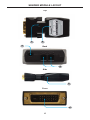
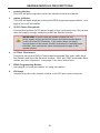
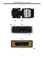
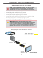
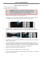
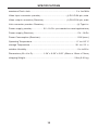
1
EXT-DVI-FM2500
User Manual
www.gefen.com
ASKING FOR ASSISTANCE
Technical Support:
Telephone
Fax
(818) 772-9100
(800) 545-6900
(818) 772-9120
Technical Support Hours:
8:00 AM to 5:00 PM Monday through Friday, Pacific Time
Write To:
Gefen LLC
c/o Customer Service
20600 Nordhoff St
Chatsworth, CA 91311
www.gefen.com
[email protected]
Notice
Gefen LLC reserves the right to make changes in the hardware, packaging, and
any accompanying documentation without prior written notice.
DL DVI 2FO Extender is a trademark of Gefen LLC
© 2012 Gefen, LLC. All rights reserved.
All trademarks are the property of their respective owners.
Rev A1
CONTENTS
1
Introduction
2
Operation Notes
3
Features
4
Sender Module Layout
5
Sender Module Descriptions
6
Receiver Module Layout
7
Receiver Module Descriptions
8
Connecting the DL DVI 2FO Extender
8
Wiring Diagram
9
EDID Programming
10 Specifications
11 Warranty
INTRODUCTION
Congratulations on your purchase of the DL DVI 2FO Extender. Your complete
satisfaction is very important to us.
Gefen
Gefen delivers innovative, progressive computer and electronics add-on solutions
that harness integration, extension, distribution and conversion technologies.
Gefen’s reliable, plug-and-play products supplement cross-platform computer
systems, professional audio/video environments and HDTV systems of all sizes
with hard-working solutions that are easy to implement and simple to operate.
The Gefen DL DVI 2FO Extender
The Dual Link DVI fiber optic module extender with Virtual EDID extends duallink DVI up to 3300 feet (1 kilometer) to a display supporting resolutions up to
3840 x 2400 (WQXGA) using a two-strand 50/125μm laser-optimized multimode
(OM3) LC-terminated fiber optic cable. Optical signal transmission provides
galvanic isolation and immunity to electromagnetic interference compared to
similar copper-based extension modules.
The Virtual EDID feature programs the display EDID into the Sender module to
ensure fast integration and compatibility between the source and the display.
The attractive and compact Sender and Receiver modules fit neatly behind the
equipment for a clean installation, making it a great way to extend dual-link DVI.
How It Works
The Sender module plugs into the DVI source. The Receiver module plugs into
the dual-link display. Connect a two-strand multimode LC-terminated fiber optic
cable from the Sender to the Receiver module. Plug the power supply into the
Receiver module and a vibrant Hi-Def picture will appear on your display.
1
OPERATION NOTES
READ THESE NOTES BEFORE INSTALLING OR OPERATING
THE DL DVI 2FO EXTENDER
•
The fiber optics cable must be treated carefully when connectors are
exposed. They are susceptible to dust which can contribute to loss of pixels.
•
The DL DVI 2FO Extender works for all DVI displays and supports dual link
resolutions up to 3840 x 2400.
•
The Sender module does not need to be powered externally unless the
source does not supply enough power through the DVI connector.
•
Extension distance will depend upon the type of fiber optic cable that is
used:
•
•
Up to 3300 feet (1 kilometer) using two-strand OM3 multimode fiber
optic cable.
•
Up to 1650 feet (500 meters) using two-strand OM2 multimode fiber
optic cable.
•
Up to 1000 feet (300 meters) using two-strand OM1 multimode fiber
optic cable.
Supports DDWG standard for DVI monitors.
2
FEATURES
Features
•
Extends dual-link DVI up to 3300 feet (1 kilometer) over two strands of OM3
(laser-optimized 50/125μm) multimode fiber optic cable
•
Supports resolutions up to 3840 x 2400 (dual-link DVI)
•
Virtual EDID allows EDID copying from the display to the source
•
Fiber optic transmission eliminates electromagnetic interference (EMI)
•
Sturdy metal die-cast enclosures are perfect for professional and industrial
applications
•
Compact Sender and Receiver modules provide a clean, easy installation
•
Use Gefen CAB-2LC-xxx OM1 Fiber Optic Link Cables for distances from
30 - 330 feet (9 - 100 meters)
•
FCC and CE-compliant for EMI/RFI emission
Package Includes
(1)
(1)
(2)
(1)
DL DVI 2FO Extender - Sender module
DL DVI 2FO Extender - Receiver module
5V DC Power supplies
Quick Start Guide
3
SENDER MODULE LAYOUT
Top
1
3
2
Back
4
Side
5
Front
6
4
SENDER MODULE DESCRIPTIONS
1
Power Indicator
This LED will glow bright blue when the Sender module is powered.
2
Status Indicator
This LED will flash bright blue during the EDID programming procedure. See
page 9 for more information.
3
5V DC Power Receptacle
Connect the optional 5V DC power supply to this receptacle only if the source
does not supply enough voltage to power the Sender module.
IMPORTANT: In most cases the Sender module will nott require a
power supply as long as the DVI source provides sufficient power
on pin 14 of the DVI connector. If the source does not supply
enough power to the Sender module (indicated by a flashing power
indicator), then connect the other included power supply to the
Sender module.
4
LC Fiber Connectors
Connect a two-strand OM3 LC-terminated multimode fiber optic cable from
the Sender module to the Receiver module. OM1 and OM2 multimode fiber
cables are also supported. See page 2 for more information.
5
EDID Programming Button
See page 9 for more information on using this feature.
6
DVI Input
Connect this part of the Sender module to the DVI port on the computer.
5
RECEIVER MODULE LAYOUT
Top
1
3
2
Back
4
Front
5
6
RECEIVER MODULE DESCRIPTIONS
1
Power Indicator
This LED will glow bright blue when the Receiver module is powered.
2
Status Indicator
This LED will flash bright blue during the EDID programming procedure. See
page 9 for more information.
3
5V DC Power Receptacle
Connect this cable to the included 5V DC power supply.
4
LC Fiber Connectors
Connect a single strand of OM3 LC-terminated multimode fiber optic cable from
the Sender module to the Receiver module. OM1 and OM2 multimode fiber
cables are also supported. See page 2 for more information.
5
DVI Output
Connect this part of the Receiver module to the DVI display.
7
CONNECTING THE DL DVI 2FO EXTENDER
How to Connect the DL DVI 2FO Extender
STOP: If EDID programming is required, then skip to the EDID
Programming Procedure on the next page. If an EDID is not
required by the DVI source, then programming is not necessary.
1.
Connect the Sender module to the DVI source.
2.
Connect the Receiver module to the DVI display.
3.
Connect the Sender module and Receiver module together using
two-strand multimode LC-terminated fiber optic cable.
4.
Connect the included power supply to the Receiver module.
IMPORTANT: In most cases the Sender module will nott require a
power supply as long as the DVI source provides sufficient power
on pin 14 of the DVI connector. If the source does not supply
enough power to the Sender module (indicated by a flashing power
indicator), then connect the other included power supply to the
Sender module.
Wiring Diagram for the DL DVI 2FO Extender
FIBER OPTIC CABLE
Sender
Dual-Link
DVI Source
Receiver
Dual-Link
DVI Display
8
EXT-DVI-FM2500
EDID PROGRAMMING
EDID Programming Procedure
EDID programming is required
d if the maximum resolution of the display does not
support 2560 x 1600 (WQXGA).
IMPORTANT: The DL DVI 2FO Extender (Sender module) has
a default built-in EDID of 2560 x 1600. If the Sender module is
programmed with another EDID, the default EDID will be erased.
Once the default EDID is erased, it cannot be restored.
1.
Power on the DVI display (or other sink device).
2.
Connect one of the included 5V DC power supplies to the Sender module
and make sure that the status indicator is ON, as shown below.
3.
Use a small pin or paperclip to press the recessed EDID button on the
Sender module. The blue status indicator LED light will blink and then turn
off.
4.
Connect the Sender module to the display (or the sink device containing the
EDID to be recorded).
5.
The status indicator on the top of the Sender module will begin to blink
rapidly, indicating that the EDID is being read from the display and stored by
the Sender module. After about 7 - 8 seconds, the status indicator will stop
flashing, indicating that the EDID programming is complete.
6.
Disconnect the Sender module from the sink.
7.
Disconnect the power supply from the Sender module.
8.
Refer to the instructions on the previous page for information on connecting
the DL DVI 2FO Extender.
9
SPECIFICATIONS
Maximum Pixel Clock.......................................................................... 2 x 165 MHz
Video Input Connector (Sender)......................................... (1) DVI-D 24-pin, male
Video Output Connector (Receiver).................................... (1) DVI-D 24-pin, male
Link Connector (Sender / Receiver)..................................................... (2) Type LC
Power Supply (Sender).................. 5V / 1A DC (not needed for most applications)
Power Supply (Receiver)....................................................................... 5V / 1A DC
Power Consumption (Receiver)........................................................... 1.5W (max.)
Operating Temperature........................................................................ 0° to +50° C
Storage Temperature........................................................................ -30° to +70° C
Relative Humidity................................................................................... 0% to 85%
Dimensions (W x H x D)................. 1.54” x 0.59” x 2.83” (39mm x 15mm x 72mm)
Shipping Weight............................................................................... 2 lbs (0.91 kg)
10
WARRANTY
Gefen warrants the equipment it manufactures to be free from defects in material
and workmanship.
If equipment fails because of such defects and Gefen is notified within two (2)
years from the date of shipment, Gefen will, at its option, repair or replace the
equipment, provided that the equipment has not been subjected to mechanical,
electrical, or other abuse or modifications. Equipment that fails under conditions
other than those covered will be repaired at the current price of parts and labor in
effect at the time of repair. Such repairs are warranted for ninety (90) days from
the day of reshipment to the Buyer.
This warranty is in lieu of all other warranties expressed or implied, including
without limitation, any implied warranty or merchantability or fitness for any
particular purpose, all of which are expressly disclaimed.
1.
Proof of sale may be required in order to claim warranty.
2.
Customers outside the US are responsible for shipping charges to and from
Gefen.
3.
Copper cables are limited to a 30 day warranty and cables must be in their
original condition.
The information in this manual has been carefully checked and is believed to
be accurate. However, Gefen assumes no responsibility for any inaccuracies
that may be contained in this manual. In no event will Gefen be liable for
direct, indirect, special, incidental, or consequential damages resulting from
any defect or omission in this manual, even if advised of the possibility of such
damages. The technical information contained herein regarding the features and
specifications is subject to change without notice.
For the latest warranty coverage information, refer to the Warranty and Return
Policy under the Support section of the Gefen Web site at www.gefen.com.
PRODUCT REGISTRATION
Please register your product online by visiting the Register Product page
under the Support section of the Gefen Web site.
11
Rev A1
20600 Nordhoff St., Chatsworth CA 91311
1-800-545-6900
818-772-9100
www.gefen.com
Pb
This product uses UL or CE listed power supplies.
fax: 818-772-9120
[email protected]