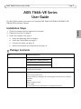
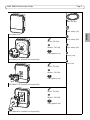
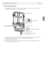
1
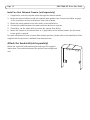
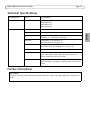
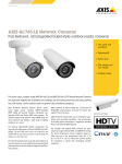
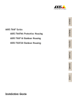
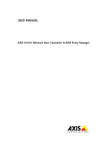
USER GUIDE
AXIS T98A15-VE Surveillance Cabinet
AXIS T98A16-VE Surveillance Cabinet
AXIS T98A17-VE Surveillance Cabinet
AXIS T98A18-VE Surveillance Cabinet
ENGLISH
AXIS T98A-VE Series
Legal Considerations
Video and audio surveillance can be prohibited by laws that
vary from country to country. Check the laws in your local
region before using this product for surveillance purposes.
Equipment Modifications
This equipment must be installed and used in strict
accordance with the instructions given in the user
documentation. This equipment contains no
user-serviceable components. Unauthorized equipment
changes or modifications will invalidate all applicable
regulatory certifications and approvals.
Liability
Every care has been taken in the preparation of this
document. Please inform your local Axis office of any
inaccuracies or omissions. Axis Communications AB cannot
be held responsible for any technical or typographical errors
and reserves the right to make changes to the product and
documentation without prior notice. Axis Communications
AB makes no warranty of any kind with regard to the
material contained within this document, including, but not
limited to, the implied warranties of merchantability and
fitness for a particular purpose. Axis Communications AB
shall not be liable nor responsible for incidental or
consequential damages in connection with the furnishing,
performance or use of this material. This product is only to
be used for its intended purpose.
RoHS
This product complies with both the European RoHS
directive, 2002/95/EC, and the Chinese RoHS
regulations, ACPEIP.
WEEE Directive
The European Union has enacted a Directive
2002/96/EC on Waste Electrical and Electronic
Equipment (WEEE Directive). This directive is
applicable in the European Union member states.
The WEEE marking on this product (see right) or
its documentation indicates that the product must not be
disposed of together with household waste. To prevent
possible harm to human health and/or the environment, the
product must be disposed of in an approved and
environmentally safe recycling process. For further
information on how to dispose of this product correctly,
contact the product supplier, or the local authority
responsible for waste disposal in your area. Business users
should contact the product supplier for information on how
to dispose of this product correctly. This product should not
be mixed with other commercial waste.
Support
Should you require any technical assistance, please contact
your Axis reseller. If your questions cannot be answered
immediately, your reseller will forward your queries through
the appropriate channels to ensure a rapid response. If you
are connected to the Internet, you can:
• download user documentation and firmware updates
• find answers to resolved problems in the FAQ database.
Search by product, category, or phrases
• report problems to Axis support by logging in to your
private support area
Safeguards
Please read through this User Guide carefully before installing the Axis product. Keep the User
Guide for further reference.
•
•
•
The Axis product should be installed by a trained professional. Observe relevant national
and local regulations for the installation.
Transportation
•
When transporting the Axis product, use the original packaging or equivalent to prevent
damage to the product.
ENGLISH
•
Only use applicable tools when installing the Axis product; excessive force could cause
damage to the product.
Do not use chemicals, caustic agents, or aerosol cleaners. Use a damp cloth for cleaning.
Use only accessories that comply with technical specification of the product. These can be
provided by Axis or a third party.
AXIS T98A-VE Series User Guide
Page 5
AXIS T98A-VE Series
User Guide
This User Guide provides instructions for installing AXIS T98A15-VE/T98A16-VE/T98A17-VE/
T98A18-VE Surveillance Cabinet.
Installation Steps
ENGLISH
1. Check the package contents against the list below.
2. Hardware overview. See page 6.
3. Install the hardware. See page 9.
• Install the Mounting Plate, see page 9
• Install the Cabinet Base, see page 11.
• Connect the Cables, see page 12.
• Attach the Sunshield (sold separately), see page 14.
Package Contents
Item
Models/variants/notes
Surveillance Cabinet
AXIS T98A15-VE, including screw kit
See illustrations on page 7
AXIS T98A16-VE, including screw kit
AXIS T98A17-VE, including screw kit
AXIS T98A18-VE, including screw kit
Printed materials
AXIS T98A-VE Series User Guide (this document)
Axis Warranty Document
Optional accessories
Sunshield
Corner mount, pole mount
Electrical safety kit 120/230 V AC, including door switch (for e.g. intrusion
detection)
Midspan
Media converter switch
Power supply
See www.axis.com for information on available accessories
Page 6
AXIS T98A-VE Series User Guide
Hardware Overview
Cabinet base
Dehumidifying
membrane (7x)
Hinge pin
Hinge
Left (2x), right (2x)
DIN rail
Electrical safety
cover
Cable hole and gasket
M25 (3/4”) (2x)
M20 (1/2”) (3x)
Drill-out (5x)
Cut-out (5x)
Mounting plate
Cabinet door
Hook
Slot for door switch
(used for e.g. intruion detection)
Screw hole for
wall mount
ø6.55 mm (0.26”) (6x)
Screw hole for
bracket mount
ø8.55 mm (0.35”) (4x)
Knock-out
M25 (3/4” (5x)
Knock-out
M50 (1 1/2”); M25 (3/4”)
Device mounting bracket
Knock-out
M25 (3/4”) (8x)
AXIS T98A-VE Series User Guide
Page 7
Cable tie (6x)
Cable clamp (1x)
Cable clamp (5x)
Screw, T20 (4x)
Washer, T20 (4x)
Cable gasket (3x)
Cable clamp (2x)
Screw (12x)
AXIS T98A16-VE (bracket sold separately)
Screw (2x)
Screw, T30 (4x)
Washer, T20 (4x)
Cable gasket (2x)
AXIS T98A17-VE (bracket sold separately)
Screw, T30 (6x)
Washer, T20 (6x)
Cable gasket (2x)
AXIS T98A18-VE (bracket sold separately)
ENGLISH
AXIS T98A15-VE
Page 8
AXIS T98A-VE Series User Guide
Screw Torque Guide
Screw
Torque
Secure cabinet base to mounting plate
3.0 Nm ±0.2
2.21 lb-ft ±0.15
Attach electrical safety cover to cabinet base
0.8 Nm ±0.1
0.59 lb-ft ±0.07
Attach cabinet door to cabinet base
3.5 Nm ±0.2
2.58 lb-ft ±0.15
Screws for attaching various items inside the cabinet
0.8 Nm ±0.1
0.59 lb-ft ±0.07
Attach network camera bracket to cabinet cover AXIS T98A16-VE
3.0 Nm ±0.2
2.21 lb-ft ±0.15
Attach network camera bracket to cabinet cover AXIS T98A17-VE
1.2 Nm ±0.2
0.89 lb-ft ±0.15
Attach network camera bracket to cabinet cover AXIS T98A18-VE
3.0 Nm ±0.2
2.21 lb-ft ±0.15
AXIS T98A-VE Series User Guide
Page 9
Install the Hardware
The electrical connections shall be made by a certified electrician.
To avoid condensation, do not assemble or disassemble the product during rain.
•
•
•
The hinges have a stop that locks the cabinet door at 105°.
The cabinet door can be left or right hinged; move the hinge pins to the preferred side.
For easy installation, the cabinet door can be removed while installing the cabinet base.
Install the Mounting Plate
1. Install the selected mounting bracket (corner mount/pole mount — sold separately) according
to the instructions supplied with the mounting bracket. If drilling is required, make sure to use
drill bits, screws, and plugs that are appropriate for the material. See www.axis.com for information on available mounting accessories.
2. Remove knock-outs for the cables in the mounting plate as required.
•
•
For cables routed from below, use the bottom knock-outs. For cables routed from behind,
use the rear knock-outs.
To remove a knock-out, put a screwdriver blade against one of the knock-out tabs and
strike the end of the screwdriver handle lightly with a hammer. Use pliers to break the rest
of the tabs and remove the knock-out.
Hook (4x)
Screw holes for wall mount
ø6.55 mm (0.26”) (6x)
Screw holes for pole and corner mount (sold separately)
ø8.55 mm (0.35”) (4x)
Knock-out M25 (3/4”) (5x)
Knock-out M50 (1 1/2”); M25 (3/4”)
Knock-out M25 (3/4”) (8x)
3. Mount the mounting plate on the wall or the selected bracket.
ENGLISH
•
•
Page 10
AXIS T98A-VE Series User Guide
Install the Devices
1. The included device mounting bracket can be used for attaching devices such as power supplies
or midspans. Attach these devices to the device mounting bracket with the supplied cable ties
or attached them to the DIN rail in the cabinet.
2. If applicable, attach the device mounting bracket to the cabinet base using the supplied screws.
DIN rail
DIN rail
Device mounting
bracket
Screw (2x)
3. Snap on the other devices required for the installation, for example an electrical safety kit (sold
separately), surge protectors, or switches to the DIN rail according to the manufacturers’
instructions. Additional DIN rails (not included) can be attached to the cabinet as required.
AXIS T98A-VE Series User Guide
Page 11
Install the Cabinet Base
1. If required, open drill-outs or cut-outs for extra cable holes in the cabinet base. Markings indicate where these cable holes can be drilled or cut out.
Cabinet base
Drill-out (5x)
Secure screw (2x)
and screw holes
Cut-out (5x)
Alignment indicator
Mounting plate
Conduit for cable protection
(not included)
2. Hang the cabinet base on the hooks of the mounting plate. Align the lower end of the cabinet
with the alignment indicator for easy access while connecting the cables.
3. Connect the cables, see page 12.
4. Slide the cabinet base to the bottom position and secure it to the mounting plate with the
secure screws (torque 3.0 Nm ±0.2).
ENGLISH
Gasket (5x)
Page 12
AXIS T98A-VE Series User Guide
Connect the Cables
The electrical connections and conduit installations shall be made by a certified electrician and
in compliance with local regulations.
To prepare a cable with a gasket, gently force the cable through the gasket provided and attach the
appropriate connector. It may be necessary to pierce a hole in the gasket with a screwdriver.
•
•
Do not force the connector into the gasket.
Do not pierce the gasket with a knife or other sharp object.
1. Route the cables required for the installation through conduits (not included), cable gaskets
and cable holes.
2. Attach the cable gaskets to the cable holes.
Cable gaskets shall be attached to all open cable holes in the cabinet base to maintain the
product’s IP rating. If the holes are not sealed, water may seep into the cabinet and cause
damage to the devices inside.
3. Connect the cables to and between the devices, except the power supply,
according to the manufacturers’ instructions. Use the supplied cable clamps to
keep the cables organized. If installing an Axis network camera on the door,
refer to Install an Axis Network Camera (sold separately), on page 14.
The power supply shall always be connected to the mains supply at the end of the installation.
4. If required, narrow the supplied electrical safety cover by cutting along the perforated line.
5. Open slots in the electrical safety cover as required by breaking the tabs.
6. Connect the power supply to the mains supply.
AXIS T98A-VE Series User Guide
Page 13
7. Attach the electrical safety cover using the supplied screws (torque 0.8 Nm ±0.1).
Screw T20 (2x)
Electrical safety cover
ENGLISH
Perforated line
for narrowing of cover
8. Switch on the mains supply.
9. Move the hinge pins to the preferred side and hang the door on the hinges.
10. Close the cabinet door and secure it with the secure screws (torque 3.5 Nm ±0.2).
Secure screw (4x)
Hinge pin (2x)
Page 14
AXIS T98A-VE Series User Guide
Install an Axis Network Camera (sold separately)
1. If applicable, route the required cables through the camera bracket.
2. Route the required cables trough the supplied cable gaskets. See Connect the Cables, on page
12 for instructions on how to prepare a cable with a gasket.
3. Attach the cable gaskets to the cable holes in the cabinet door.
4. Connect the cables between the camera and the devices as required.
5. If available, use the safety wire to prevent the camera from falling.
6. Attach the camera to the cabinet door or, if applicable, to the camera bracket. See the screw
torque guide on page 8.
For more information on how to install Axis network products, please refer to the Installation Guide
supplied with the product or available from www.axis.com
Attach the Sunshield (sold separately)
Attach the sunshield (sold separately) according to the supplied
instructions. The sunshield protects the cabinet from sunlight and
rain.
AXIS T98A-VE Series User Guide
Page 15
Technical Specifications
Item
Specifications
Surveillance Cabinet
Model
AXIS T98A15-VE
AXIS T98A16-VE
AXIS T98A17-VE
AXIS T98A18-VE
General
Casing
Polycarbonate
Environment
Indoor/outdoor
Operating conditions
-40 ºC to +75 ºC (-40 ºF to 167 ºF)
Humidity 15 – 100% RH (condensing)
Approvals
IEC 60068-2-6, IEC 60068-2-27
IEC 60529 IP66, IEC 62262 IK10
Weight
2.4 kg (5.1 lb.)
AXIS T98A16-VE, AXIS T98A18-VE: 2.5 kg (5.5 lb.)
Dimensions
120 mm x 161 mm x 404 mm (4.7" x 6.4" x 15.9")
Included Accessories
Pre-mounted cable gaskets, pre-mounted DIN rail, mounting
plate, cable clamps, cable straps, electrical safety cover,
device mounting bracket, User Guide
Optional Accessories
Corner bracket, pole mount bracket, sunshield, cable gasket,
electrical safety kit, midspan, media converter switch, power
supply
Further Information
Learn more!
Visit Axis learning center www.axis.com/academy for useful trainings, webinars, tutorials and
guides.
ENGLISH
Function/group
User Guide
AXIS T98A-VE Series
© Axis Communications AB, 2012
Ver.1.0
Printed: June 2012
Part No. 47698