1
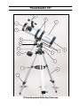
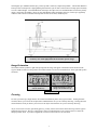
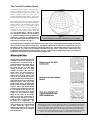
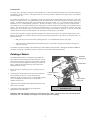
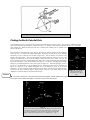
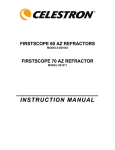
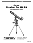
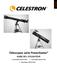
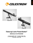
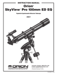
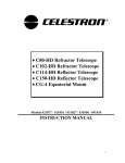
PowerSeeker 127
INSTRUCTION MANUAL
#21049
INTRODUCTION
Congratulations on your purchase and welcome to the Celestron world of amateur astronomy. Some of the terms
and parts described in these instructions may be new to you, so a few commonly used terms you’ll want to be
familiar with are defined below.
Equatorial mount – a type of mounting that allows the telescope to be aligned with the earth's axis in order to
track the motion of the sky.
Focal length - the distance from the optical center of the lens to the point where the incoming light rays converge,
creating a clear, focused image.
Primary Mirror - It gathers incoming light to create a sharply focused image.
Reflecting telescope – an optical design in which light is reflected off of a curved mirror that converges the light
into a small disk that is then magnified using an eyepiece.
First, you need to take the time to familiarize yourself with the parts of your PowerSeeker telescope, then assemble
it, following the easy instructions provided. Next, read over the operating instructions and become familiar with
how your telescope works, to prepare for hours of viewing enjoyment.
CAUTION: READ THIS SECTION BEFORE USING YOUR TELESCOPE
Your PowerSeeker telescope is designed to give you hours of fun and rewarding observing. However, there are a
few things to be aware of before using your telescope that will ensure your safety and protect your equipment.
NEVER LOOK DIRECTLY AT THE SUN WITH THE NAKED EYE OR WITH A TELESCOPE. NEVER POINT
YOUR TELESCOPE AT THE SUN UNLESS YOU’RE USING THE PROPER SOLAR FILTER. PERMANENT
AND IRREVERSIBLE EYE DAMAGE MAY RESULT.
NEVER USE YOUR TELESCOPE TO PROJECT AN IMAGE OF THE SUN ONTO ANY SURFACE, OR USE
AN EYEPIECE SOLAR FILTER OR A HERSCHEL WEDGE. INTERNAL HEAT BUILD-UP CAN DAMAGE
THE TELESCOPE AND/OR ANY ACCESSORIES THAT MAY BE ATTACHED TO IT.
NEVER LEAVE YOUR TELESCOPE UNSUPERVISED, ESPECIALLY WHEN CHILDREN ARE PRESENT.
THIS ALSO HOLDS TRUE FOR ADULTS WHO MAY NOT BE FAMILIAR WITH THE CORRECT
OPERATING PROCEDURES FOR YOUR TELESCOPE.
ALWAYS COVER THE FINDERSCOPE WHEN USING YOUR TELESCOPE WITH THE CORRECT SOLAR
FILTER. ALTHOUGH SMALL IN APERTURE, THIS INSTRUMENT HAS ENOUGH LIGHT GATHERING
POWER TO CAUSE PERMANENT AND IRREVERSIBLE EYE DAMAGE. THE IMAGE PROJECTED BY THE
FINDERSCOPE IS HOT ENOUGH TO BURN SKIN OR CLOTHING.
2
PowerSeeker 127
a
b
c
p
o
n
m
l
e
f
k
g
j
h
i
127mm Newtonian Reflecting Telescope
3
d
THE POWERSEEKER 127 Reflector
The PowerSeeker is a Newtonian reflecting telescope that comes on an equatorial mount. This section instructs you
on the proper assembly and use of your PowerSeeker telescope, which is shipped in one box, containing all the parts
you need to assemble it. Unpack and lay out all of the parts in a large, clear area where you’ll have room to work.
Use the list below and the telescope diagram to confirm you have, and can identify each part.
PowerSeeker 127
a.
b.
c.
d.
e.
f.
g.
h.
Finderscope
Tube Rings
Optical Tube
Collimation Screws
Slow Motion Controls
Equatorial Mount
Latitude Adjustment Screw
Tripod Leg
i.
j.
k.
l.
m.
n.
o.
p.
Tripod Extension Screws
Accessory Tray
Counterweight
Counterweight Bar
Right Ascension Setting Circle
Declination Setting Circle
Focuser
Eyepiece
Assembling Your Telescope
1.
To set up the tripod, spread the legs outward until they are fully extended. Extend the center portion of each of the
three tripod legs down 6-8". Use the three tightening screws located at the bottom of each leg to secure the
extended legs in place.
2.
Place the accessory tray on top of tripod's center leg brace. Thread the tray's threaded post into the threaded hole
in the center of the leg brace.
Attaching the Equatorial Mount
1.
Locate the equatorial mount and place the base of the mount through the hole in the center of the tripod mounting
platform. From underneath the tripod mounting platform, thread the mounting bolt with washer into the threaded
hole on the bottom of the equatorial mount.
2.
Thread the latitude adjustment screws into the equatorial mount until both screws are touching the inside of the
mount and the mount can no longer pivot up and down.
3.
Locate the counterweight bar and counterweight. Thread the threaded end of the counterweight bar into the Dec
axis of the equatorial mount. Remove the safety screw and washer from the other end of the counterweight bar.
Loosen the counterweight locking bolt so that the screw is no longer obstructing the center hole of the
counterweight. Slide the counterweight half way up the counterweight bar and tighten the
locking screw to secure the counterweight in place. Thread the safety screw and washer
on to the end of the counterweight bar.
Before attaching the optical tube, the counterweight and slow motion controls should be added
to the mount:
4.
Slide the chrome end of the slow motion control cables onto the equatorial mount gear
shaft. See Figure 1. The longer cable should attach to the Right Ascension axis and the
shorter cable attaches to the Declination axis.
Figure 1
4
Attaching the Optical Tube
You are now ready to put the telescope optical tube (c) onto the equatorial mount (f).
1.
Slightly loosen the screws that hold the mounting rings on the telescope in place.
2.
Slide the rings apart so that each is at the same distance as the holes in the mounting platform.
3.
Place the telescope tube on the mount so that the treaded post at the bottom of the tube rings go through the
holes on the mounting platform.
4.
Thread a wing nut onto the end of the threaded posts and tighten to secure the tube to the mount.
5.
Tighten the screws that hold the mounting rings in place. This will keep the telescope from sliding back and
forth in the mounting rings.
Attaching the Accessories
Your telescope comes with the following accessories:
•
•
•
•
•
1.
2.
3.
20mm eyepiece 1¼"
4mm eyepiece 1¼ "
3x Barlow Lens 1¼"
5x24 finderscope
The Sky® L1 Planetarium software
Remove the caps from the focuser draw tube (o).
Place the chrome barrel end of the eyepiece into the focuser. Lock it into place with the thumb screw on the
side of the focuser.
Your telescope also comes with a 3x Barlow lens which triples the magnifying power of each eyepiece (see
Magnification section of the manual). To use the barlow lens, insert the barlow lens directly into the focuser.
Then start by using the low power eyepiece such as the 20mm, and insert it directly into the barlow lens.
.
Attaching the Finderscope
1.
Remove the two small, silver thumbscrews located on top of the
telescope tube. See Figure 2.
2. Place the finderscope bracket over the two holes in the telescope tube,
lining up the holes on the finderscope bracket with those in the
telescope tube.
Insert the thumbscrews through the finderscope bracket and thread them into
the telescope tube.
Using your Telescope
Moving Your Telescope:
To change the direction your telescope is pointing:
1.
Figure 2
To move the telescope in declination (north/south) there are two
options. For large and quick movements, loosen the declination knob (see figures 8) when moving the
telescope and then tighten the knob when you are near the position you want. For very small movements and
fine adjustments, use the declination cable. The declination cable has a range of about 30° and if you come to
the stop at the end of its travel, do not try to force movement when the declination cable has reached the
stop. Instead loosen the declination knob and manually move the telescope in declination until you pass the
object in the opposite direction. Then tighten the knob and reverse the direction of the declination cable.
5
2.
To move the telescope in right ascension (east/west) there are two options. For large and quick movements,
loosen the right ascension knob when moving the telescope and then tighten the knob when you are near the
position you want. For very small movements and fine adjustments, turn the right ascension cable. Unlike
the declination cable, the right ascension cable has 360˚ of continuous motion.
Balancing the Telescope in Right Ascension (R.A.):
The telescope should be properly balanced in order for it to move smoothly in both axes. Proper balance is essential if
using an optional motor drive for accurate tracking.
1.
To balance the right ascension axis, move the counterweight shaft so it is parallel (horizontal) to the ground.
(See figure 3). Slowly release the right ascension knob and see if the optical tube moves. If the optical tube
moves, then slide the counterweight up or down the counterweight shaft until the optical tube remains
stationary in the parallel position to the ground. When this happens, make sure the counterweight lock is
tight.
Balancing the Telescope in Declination (DEC):
The telescope should also be balanced on the declination axis to prevent any sudden motions when the DEC clamp is
released. To balance the telescope in DEC:
1.
Release the R.A. clamp and rotate the telescope so that it is on one side of the mount (i.e., as described in the previous
section on balancing the telescope in R.A.).Lock the R.A. clamp to hold the telescope in place. Release the DEC
clamp and rotate the telescope until the tube is parallel to the ground (see figure 4). Release the tube —
GRADUALLY — to see which way it rotates around the declination axis. DO NOT LET GO OF THE
TELESCOPE TUBE COMPLETELY! Loosen the screws that hold the telescope tube inside the mounting rings
and slide the telescope tube either forwards or backwards until it remains stationary when the DEC clamp is released.
Tighten the tube ring screws firmly to hold the telescope in place.
Figure 4 - Balancing in Declination
Figure 3 - Balancing in R.A.
Telescope Basics
A telescope is an instrument that collects and focuses light. The nature of the optical design determines how the light
is focused. Some telescopes, known as refractors, use lenses. Other telescopes, known as reflectors, use mirrors. A
Newtonian reflector uses a single concave mirror as its primary. Light enters the tube traveling to the mirror at the
back end. There light is bent forward in the tube to a single point, its focal point. Since putting your head in front of
the telescope to look at the image with an eyepiece would keep the reflector from working, a flat mirror called a
diagonal intercepts the light and points it out the side of the tube at right angles to the tube. The eyepiece is placed
there for easy viewing.
Newtonian Reflector telescopes replace heavy lenses with mirrors to collect and focus the light, providing much more
light-gathering power for the dollar. Because the light path is intercepted and reflected out to the side, you can have
6
focal lengths up to 1000mm and still enjoy a telescope that is relatively compact and portable. A Newtonian Reflector
telescope offers such impressive light-gathering characteristics you can take a serious interest in deep space astronomy
even on a modest budget. Newtonian Reflector telescopes do require more care and maintenance because the primary
mirror is exposed to air and dust. However, this small drawback does not hamper this type of telescope’s popularity
with those who want an economical telescope that can still resolve faint, distant objects.
Figure 5
A cutaway view of the light path of the Newtonian optical design
Image Orientation
Newtonian reflectors produce a right-side-up image but the image will appear rotated based on the location of the
eyepiece holder in relation to the ground. Newtonian reflectors are best for astronomical use where right-side-up does
not matter.
Actual image orientation as seen
with the unaided eye
Upside-down image, as viewed
though a Newtonian telescope
Figure 6
Focusing
To focus your telescope, simply turn the focus knob located directly below the eyepiece holder. Turning the knob
clockwise allows you to focus on an object that is farther than the one you are currently observing. Turning the knob
counterclockwise from you allows you to focus on an object closer than the one you are currently observing.
•If you wear corrective lenses (specifically glasses), you may want to remove them when observing with an eyepiece
attached to the telescope. However, when using a camera you should always wear corrective lenses to ensure the
sharpest possible focus. If you have astigmatism, corrective lenses must be worn at all times.
7
The Celestial Coordinate System
To help find objects in the sky, astronomers use a
celestial coordinate system that is similar to our
geographical coordinate system here on Earth. The
celestial coordinate system has poles, lines of
longitude and latitude, and an equator. For the most
part, these remain fixed against the background stars.
The celestial equator runs 360 degrees around the
Earth and separates the northern celestial hemisphere
from the southern. Like the Earth's equator, it bears
a reading of zero degrees. On Earth this would be
latitude. However, in the sky this is referred to as
declination, or DEC for short. Lines of declination
are named for their angular distance above and
below the celestial equator. The lines are broken
down into degrees, minutes of arc, and seconds of
arc. Declination readings south of the equator carry
a minus sign (-) in front of the coordinate and those
north of the celestial equator are either blank (i.e., no
designation) or preceded by a plus sign (+).
Figure 7
The celestial sphere seen from the outside showing R.A. and DEC.
The celestial equivalent of longitude is called Right Ascension, or R.A. for short. Like the Earth's lines of longitude, they run from
pole to pole and are evenly spaced 15 degrees apart. Although the longitude lines are separated by an angular distance, they are
also a measure of time. Each line of longitude is one hour apart from the next. Since the Earth rotates once every 24 hours, there
are 24 lines total. As a result, the R.A. coordinates are marked off in units of time. It begins with an arbitrary point in the
constellation of Pisces designated as 0 hours, 0 minutes, 0 seconds. All other points are designated by how far (i.e., how long) they
lag behind this coordinate after it passes overhead moving toward the west.
Motion of the Stars
The daily motion of the Sun across the sky
is familiar to even the most casual observer.
This daily trek is not the Sun moving as
early astronomers thought, but the result of
the Earth's rotation. The Earth's rotation
also causes the stars to do the same,
scribing out a large circle as the Earth
completes one rotation. The size of the
circular path a star follows depends on
where it is in the sky. Stars near the
celestial equator form the largest circles
rising in the east and setting in the west.
Moving toward the north celestial pole, the
point around which the stars in the northern
hemisphere appear to rotate, these circles
become smaller. Stars in the mid-celestial
latitudes rise in the northeast and set in the
northwest. Stars at high celestial latitudes
are always above the horizon, and are said
to be circumpolar because they never rise
and never set. You will never see the stars
complete one circle because the sunlight
during the day washes out the starlight.
However, part of this circular motion of
stars in this region of the sky can be seen by
setting up a camera on a tripod and opening
the shutter for a couple hours.
The
processed film will reveal semicircles that
revolve around the pole. (This description
of stellar motions also applies to the
southern hemisphere except all stars south
of the celestial equator move around the
south celestial pole.)
Figure 8
All stars appear to rotate around the celestial poles. However, the appearance of this motion
varies depending on where you are looking in the sky. Near the north celestial pole the stars
scribe out recognizable circles centered on the pole (1). Stars near the celestial equator also
follow circular paths around the pole. But, the complete path is interrupted by the horizon.
These appear to rise in the east and set in the west (2). Looking toward the opposite pole, stars
curve or arc in the opposite direction scribing a circle around the opposite pole (3).
8
Latitude Scales
The easiest way to polar align a telescope is with a latitude scale. Unlike other methods that require you to find the celestial pole
by identifying certain stars near it, this method works off of a known constant to determine how high the polar axis should be
pointed (see figure 10).
The constant, mentioned above, is a relationship between your latitude and the angular distance the celestial pole is above the
northern (or southern) horizon; The angular distance from the northern horizon to the north celestial pole is always equal to your
latitude. To illustrate this, imagine that you are standing on the north pole, latitude +90°. The north celestial pole, which has a
declination of +90°, would be directly overhead (i.e., 90 above the horizon). Now, let’s say that you move one degree south —
your latitude is now +89° and the celestial pole is no longer directly overhead. It has moved one degree closer toward the northern
horizon. This means the pole is now 89° above the northern horizon. If you move one degree further south, the same thing
happens again. You would have to travel 70 miles north or south to change your latitude by one degree. As you can see from this
example, the distance from the northern horizon to the celestial pole is always equal to your latitude.
If you are observing from Los Angeles, which has a latitude of 34°, then the celestial pole is 34° above the northern horizon. All a
latitude scale does then is to point the polar axis of the telescope at the right elevation above the northern (or southern) horizon. To
align your telescope:
1.
Make sure the polar axis of the mount is pointing due north. Use a landmark that you know faces north.
2.
Adjust the mount in altitude until the latitude indicator points to your latitude. Moving the mount affects the angle the
polar axis is pointing.
This method can be done in daylight, thus eliminating the need to fumble around in the dark. Although this method does NOT put
you directly on the pole, it will limit the number of corrections you will make when tracking an object.
Pointing at Polaris
This method utilizes Polaris as a guidepost to the celestial pole.
Since Polaris is less than a degree from the celestial pole, you can
simply point the polar axis of your telescope at Polaris. Although
this is by no means perfect alignment, it does get you within one
degree. Unlike the previous method, this must be done in the
dark when Polaris is visible.
1.
Set the telescope up so that the polar axis is pointing north. See
Figure 10.
2.
Loosen the DEC clutch knob and move the telescope so that the
tube is parallel to the polar axis. When this is done, the
declination setting circle will read +90°. If the declination setting
circle is not aligned, move the telescope so that the tube is
parallel to the polar axis.
3.
Adjust the mount in altitude and/or azimuth until Polaris is in the
field of view of the finder.
4.
Center Polaris in the field of the telescope using the fine
adjustment controls on the mount.
Declination
Setting Circle
Declination
Lock
Latitude Scale
Right
Ascension
Lock
Latitude Adjustment
Screws
Right Ascension
Setting Circle
Figure 9 – Equatorial Head
PowerSeeker 127
Remember, while Polar aligning, do NOT move the telescope in R.A. or DEC. You do not want to move the telescope itself,
but the polar axis. The telescope is used simply to see where the polar axis is pointing.
9
Figure 10- Aligning the Equatorial mount to the polar axis of the Earth.
Finding the North Celestial Pole
In each hemisphere, there is a point in the sky around which all the other stars appear to rotate. These points are called the celestial
poles and are named for the hemisphere in which they reside. For example, in the northern hemisphere all stars move around the
north celestial pole. When the telescope's polar axis is pointed at the celestial pole, it is parallel to the
Earth's rotational axis.
Many methods of polar alignment require that you know how to find the celestial pole by identifying
stars in the area. For those in the northern hemisphere, finding the celestial pole is not too difficult.
Fortunately, we have a naked eye star less than a degree away. This star, Polaris, is the end star in the
handle of the Little Dipper. Since the Little Dipper (technically called Ursa Minor) is not one of the
brightest constellations in the sky, it may be difficult to locate from urban areas. If this is the case, use
the two end stars in the bowl of the Big Dipper (the pointer stars). Draw an imaginary line through them
toward the Little Dipper. They point to Polaris (see Figure 12). The position of the Big Dipper changes
during the year and throughout the course of the night (see Figure 11). When the Big Dipper is low in
the sky (i.e., near the horizon), it may be difficult to locate. During these times, look for Cassiopeia (see
Figure 12). Observers in the southern hemisphere are not as fortunate as those in the northern
hemisphere. The stars around the south celestial pole are not nearly as bright as those around the north.
The closest star that is relatively bright is Sigma Octantis. This star is just within naked eye limit
(magnitude 5.5) and lies about 59 arc minutes from the pole.
Definition
Figure 11 - The position of
the Big Dipper changes
throughout the year and the
night.
The north celestial pole is the point in the northern hemisphere around which all stars appear to rotate. The
counterpart in the southern hemisphere is referred to as the south celestial pole.
Figure 12
The two stars in the front of the bowl of the Big Dipper point to Polaris which
is less than one degree from the true (north) celestial pole. Cassiopeia, the
“W” shaped constellation, is on the opposite side of the pole from the Big
Dipper. The North Celestial Pole (N.C.P.) is marked by the “+” sign.
10
Using the Setting Circles
Setting Circles are dials (or gauges) for right ascension and declination that allow you to locate celestial objects
easily from their coordinates as listed in a star chart or atlas.
1.
The declination setting circle (see Figure 9) is scaled in degrees and the right ascension setting circle is
incremented in minutes. The circles will get you close to your target but not directly on it. Also, the accuracy of
your polar alignment will affect how accurate your setting circles read.
2.
The declination setting circle is factory set and should not need any adjustment if it reads accurately.
3.
The right ascension setting circle must be aligned. Choose a bright and easy to find star in a star chart and note
the coordinates (right ascension and declination). Find the star in the Star Pointer and then in the telescope.
Now, rotate the right ascension circle to match the coordinates of the star with the indicator mark. If you polar
aligned the telescope accurately, the declination circle should be correctly set to the proper coordinates.
4.
The right ascension setting circle does not move as the telescope moves in right ascension and thus it must by
aligned each time you want to use it to find a new object. However, you do not need to use a bright star each time
but you can use the object you are currently observing.
5.
Now, using a star chart or atlas you can find numerous objects. First move the telescope in declination to the
correct declination coordinate. Then move the telescope in right ascension until the indicator points to the correct
coordinate.
6.
After moving the telescope to the correct celestial coordinates, look through the lower power eyepiece to see if
you have located the object you wish to view. Center the object in eyepiece. If the object is not visible in the
eyepiece, gradually pan the telescope, using the right ascension and declination cables, until the object is visible.
Always start by using your lowest power eyepiece (20mm) then switching to higher power once you have found
the desired object.
Magnification
The magnification (or power) of a telescope varies depending upon the focal length of the eyepiece being used and the
focal length of the telescope.
The PowerSeeker 127 telescope has a focal length of 1000mm and comes with a 20mm 1¼" eyepiece. To calculate
magnification, use the following formula, in which FL = focal length:
Magnification =
Important!
FL (telescope) in mm
FL (eyepiece) in mm
Therefore, if you use the 20mm eyepiece your magnification is 1000/20 = 50x. The same formula can be applied to
any of your eyepieces.
Magnification through any telescope has its limits. These limits are determined by the laws of optics and the nature of
the human eye. Most of your viewing will be done in the range of 50x to 130x. Higher powers are used mainly for
lunar and sometimes planetary observing where you can greatly enlarge the image and the atmospheric conditions are
near perfect. The images at extremely high powers magnify the image, but remember that the contrast will be very
low due to the high magnification. For the brightest images with the most contrast, start by using the lower power
eyepiece with a smaller image scale.
The following magnification levels can be achieved when using the standard eyepieces in conjunction with the 3x
Barlow lens:
11
Eyepiece
Magnification
20mm
4mm
50x
250x
Mag. with 3x Barlow
Lens
150x
750x
TELESCOPE MAINTENANCE
With proper care, your telescope should rarely need any maintenance work. To maintain your telescope in the best
possible condition, observe the follow suggestions:
1.
When your telescope isn’t in use, replace all lens covers to keep dust and contaminants off the optical surfaces.
2.
A small amount of dust on any optical surface isn’t a problem and doesn’t need to be removed. If the dust builds
up, then use a can of compressed air and a camels hair brush to remove the dust. To remove fingerprints or other
contaminants, use an optical cleaning kit or the Celestron Lens Pen (#93575).
3.
If the inside of the objective lens needs cleaning, it should be done by a professional. Either have your instrument
serviced by a telescope repair facility or return it to the factory for servicing.
Collimation
Collimation or alignment of the optical system is done at the factory before shipment.
1.
If your telescope has received very rough handling during transport or is dropped, it may need collimation.
Refer to the following sketch to check if your telescope is in
collimation. If you look into the eyepiece adapter (without an
eyepiece) at the top of the focuser, this is what you should
see. If the reflection of your eye is off center, then
collimation is necessary.
2.
Adjustments to the collimation of the telescope can be made
by turning the collimation adjustment screws (d) located at
the rear of the optical tube.
3.
If your telescope is out of collimation, the best way to recollimate it is with a good collimation tool. Celestron offers a
Newtonian Collimation Tool (#94183) with detailed
instructions that make it an easy chore.
SPECIFICATIONS
Aperture
Focal Length
Focal Ratio
Mounting
Tripod
PowerSeeker 127
127mm
1000mm
f/8
Equatorial
Adjustable Aluminum Tripod
NOTE: Specifications are subject to change without notice.
12
Optional Accessories
Celestron offers a full line of optional accessories for your telescope. Please refer to the Celestron Accessory Catalog
(#93685) for a complete description, or logon to our web site at www.celestron.com.
Eyepieces – An assortment of 1¼” eyepieces are available to give you a wide range of magnifications.
•
OMNI Plössl - Plössl eyepieces have a 4-element lens designed for low-to-high power observing.
The Plössls offer razor sharp views across the entire field, even at the edges! In the 1-1/4" barrel
diameter, they are available in the following focal lengths: 4mm, 6mm, 9mm, 12.5mm, 15mm,
20mm, 25mm, 32mm and 40mm.
•
Ultima – Ultima is not really a design, but a trade name for our 5-element, wide field
eyepieces. In the 1-1/4” barrel diameter, they are available in the following focal
lengths: 5mm, 7.5mm, 10mm, 12.5mm, 18mm, 24mm, 30mm, 35mm, and 42mm.
These eyepieces are all parfocal. The 35mm Ultima gives the widest possible field of
view with a 1-1/4” diagonal.
Filters, Eyepiece - To enhance your visual observations of solar system objects,
Celestron offers a wide range of colored eyepiece filter sets that thread into the 1-1/4"
oculars. Available sets are:
#94119-10 – Orange, Light Blue, ND13%T, Polarizing (#s 21, 80A, 96ND-13, Polarizing)
#94119-20 - Deep Yellow, Red, Light Green, ND25% T (#s 12, 25, 56, 96ND-25)
#94119-30 - Light Red, Blue, Green, ND50% T (#s 23A, 38A, 58, 96ND-50)
#94119-40 - Yellow, Deep Yellow, Violet, Pale Blue (#s 8, 15, 47, 82A)
Flashlight - #93588 LED (light emitting diode) flashlight conveniently allow you to read star maps without diminishing
your night vision. Feature adjustable brightness and is lightweight.
Light Pollution Reduction (LPR) Filter (#94123) - A 1¼” filter that threads into a 1¼” eyepiece, designed to enhance
your views of deep-sky astronomical objects when observed from urban areas. The LPR filter selectively reduces the
transmission of certain wavelengths of light, specifically those produced by artificial lights. This includes mercury, and
high and low pressure sodium vapor lights. Additionally, it blocks unwanted natural light (also known as sky glow).
Sky Maps (#93722) – When learning the night sky, Celestron Sky Maps offer just the
guidance you need. The maps show all the constellations and brighter deep-sky objects
and are printed on heavy, moisture-resistant paper for durability. The front cover
features a rotating planisphere, indicating when specific constellations are visible.
Peterson First Guides® - Astronomy (#93728)
A simplified field guide to the stars, the planets and the universe featuring full color maps showing the positions of the
stars throughout the year. This useful guide also includes beautiful constellation paintings, photographs, and clear,
concise descriptions of stars, the planets, the sun, the moon, comets, black holes, galaxies and more.
Solar Filters, 114/127mm (#94134) - Celestron Solar Filters are made with Baader Astro Solar™ Safety Film. Far
superior than any existing glass, Mylar or polymer filters, they lead to brighter, sharper, and higher contrast images.
The Sun appears in its “real ”color —neutral white, and the sky adjacent to the solar limb is jet black. You can see
detail in sunspots, bright faculae near the limb and the mottled areas known as granules with these filters.
A full description of all Celestron accessories can be found on our web site at www.celestron.com
13
CELESTRON TWO YEAR WARRANTY
A.
Celestron warrants this telescope to be free from defects in materials and workmanship for two years. Celestron will repair or replace such
product or part thereof which, upon inspection by Celestron, is found to be defective in materials or workmanship. As a condition to the
obligation of Celestron to repair or replace such product, the product must be returned to Celestron together with proof-of-purchase
satisfactory to Celestron.
B.
The Proper Return Authorization Number must be obtained from Celestron in advance of return. Call Celestron at (310) 328-9560 to
receive the number to be displayed on the outside of your shipping container.
All returns must be accompanied by a written statement setting forth the name, address, and daytime telephone number of the owner,
together with a brief description of any claimed defects. Parts or product for which replacement is made shall become the property of
Celestron.
The customer shall be responsible for all costs of transportation and insurance, both to and from the factory of Celestron, and shall
be required to prepay such costs.
Celestron shall use reasonable efforts to repair or replace any telescope covered by this warranty within thirty days of receipt. In the event
repair or replacement shall require more than thirty days, Celestron shall notify the customer accordingly. Celestron reserves the right to
replace any product which has been discontinued from its product line with a new product of comparable value and function.
This warranty shall be void and of no force of effect in the event a covered product has been modified in design or function, or
subjected to abuse, misuse, mishandling or unauthorized repair. Further, product malfunction or deterioration due to normal wear
is not covered by this warranty.
CELESTRON DISCLAIMS ANY WARRANTIES, EXPRESS OR IMPLIED, WHETHER OF MERCHANTABILITY OF FITNESS FOR
A PARTICULAR USE, EXCEPT AS EXPRESSLY SET FORTH HEREIN.
THE SOLE OBLIGATION OF CELESTRON UNDER THIS LIMITED WARRANTY SHALL BE TO REPAIR OR REPLACE THE
COVERED PRODUCT, IN ACCORDANCE WITH THE TERMS SET FORTH HEREIN. CELESTRON EXPRESSLY DISCLAIMS
ANY LOST PROFITS, GENERAL, SPECIAL, INDIRECT OR CONSEQUENTIAL DAMAGES WHICH MAY RESULT FROM
BREACH OF ANY WARRANTY, OR ARISING OUT OF THE USE OR INABILITY TO USE ANY CELESTRON PRODUCT. ANY
WARRANTIES WHICH ARE IMPLIED AND WHICH CANNOT BE DISCLAIMED SHALL BE LIMITED IN DURATION TO A
TERM OF TWO YEARS FROM THE DATE OF ORIGINAL RETAIL PURCHASE.
Some states do not allow the exclusion or limitation of incidental or consequential damages or limitation on how long an implied warranty
lasts, so the above limitations and exclusions may not apply to you.
This warranty gives you specific legal rights, and you may also have other rights which vary from state to state.
Celestron reserves the right to modify or discontinue, without prior notice to you, any model or style telescope.
If warranty problems arise, or if you need assistance in using your telescope contact:
Celestron
Customer Service Department
2835 Columbia Street
Torrance, CA 90503 U.S.A.
Tel. (310) 328-9560
Fax. (310) 212-5835
Monday-Friday 8AM-4PM PST
All authorized returns should be shipped to :
Celestron
1380 Charles Willard St
Carson, CA 90747
This warranty supersedes all other product warranties.
NOTE:
This warranty is valid to U.S.A. and Canadian customers who have purchased this product from an Authorized Celestron
Dealer in the U.S.A. or Canada. Warranty outside the U.S.A. and Canada is valid only to customers who purchased from a
Celestron Distributor or Authorized Celestron Dealer in the specific country and please contact them for any warranty
service.
Celestron
2835 Columbia Street
Torrance, CA 90503
Tel. (310) 328-9560
Fax. (310) 212-5835
Web site at http//www.celestron.com
Copyright 2005 Celestron
All rights reserved.
(Products or instructions may change
without notice or obligation.)
Printed in China
#21049 01-05