1
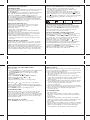
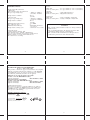
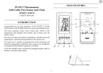
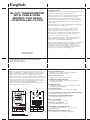
English
IN-OUT THERMOMETER
WITH CABLE FREE
SENSOR AND RADIO
CONTROLLED CLOCK
INTRODUCTION:
Congratulations with the purchase if the In/Out Thermometer
with wireless sensor and radio controlled clock.
The basic package comes with a main unit (the temperature /
clock station) and a remote unit (the thermo sensor).
The main unit has large displays for time/date, indoors
temperature and outdoors temperature as received from the
remote unit. The main unit can receive data from up to 3
remote units.
The main unit has a memory for maximum and minimum
reached temperatures of different sites.
The remote units have a range up to 30 meters, this
range can be influenced by several factors (concrete
walls, electric wires, other sending devices, etc.)
The sensors are weatherproof and can be used outdoors,
but should not be submerged into water or hung in a
place where rain can reach the unit.
The clock/calendar function is radio controlled. The day
can be displayed in 5 languages and the unit has a 2
minute crescendo weekly and daily alarm.
The clock is synchronised with the atom clock in Frankfurt
Germany, this clock has a range of 1.500 km and your
clock will receive the time signal 12 to 24 times a day
and will correct, if necessary. When you first operate
your clock, it can take up to 60 minutes before the radio
signal is received and the correct time is set.
USER'S MANUAL
( TE217/TE217EL)
17
18
NILBRAND TE217/TE217EL & TS02C MANUAL (ENG)
SIZE: W65 X H105 (mm)
BY SHAN WONG 28/11/05
When you put the main unit and the remote unit next toe ach
other, you will notice a minimal difference in temperature.
This is caused by the software used and the insulation of the
outdoors sensor, this sensor is calibrated on the average
outdoors temperature, whereas the main unit is calibrated on
the average indoors temperature. This is no defect in the units
A FOUR-LINE DISPLAY
Facilitates easy reading of remote and indoors
temperatures and calendar clock
At temperatures below freezing point the operation can be
distorted, this is caused because the batteries cannot deliver
the power needed to operate the unit correctly.
You can avoid this by using branded batteries and change
them just before the winter starts.
C MEMORY [MEM] BUTTON
Recalls the maximum or minimum temperature of
main and remote unit
F
G
TREND
A
MIN
MAX
D MODE BUTTON
Toggles the display modes and confirms entry while
setting the values for display
E ALARM BUTTON
Displays the alarm time or sets the alarm status
F SNOOZE BUTTON or SNOOZE/LIGHT BUTTON
Activate the snooze function
RADIO CONTROLLED
CH
B CHANNEL BUTTON
Display different sensor temperature
TREND
G WALL-MOUNT RECESSED HOLE
For mounting the main unit on a wall
IN
AM
ZONE
PM
PRE-AL
AM
PM
M
D
D
M
min
4 3 3 M H z
H UP ( ) BUTTON
Advances the value of a setting
w
s
W I R E L E S S
CHANNEL
MEM
I DOWN ( ) BUTTON
Decreases the value of a setting
H
J BATTERY COMPARTMENTS
Accommodates two UM-3 or “AA” size 1.5V
alkaline batteries
ALARM
ON / OFF
MODE
D
B
C
I
E
J
K REMOVABLE TABLE STAND
For standing the main unit on a flat surface
K
19
20
MAIN FEATURES: REMOTE UNIT
E
WIRELESS THERMOMETER
A
C
D
F
CHANNEL
1 2 3
SIZE AA / UM3
SIZE AA / UM3
B
RESET
A LED INDICATOR
Flashes once when the remote unit transmits a reading
Flashes twice when low battery is detected on sensor unit
B BATTERY COMPARTMENT
Accommodates two AA-size batteries
C RESET BUTTON
Press to reset all setting if you have selected
different channel.
D CHANNEL SELECTOR
Select the channel before you install batteries.
BEFORE YOU BEGIN
For best operation,
1. Insert batteries for remote units before doing so for the
main unit.
2. Place the main unit as close as possible next to the
remote unit.
3. Position the remote unit and main unit within effective
transmission range, which, in usual circumstances, is
20 to 30 meters.
Note that the effective range is vastly affected by the
building materials and where the main and remote units
are positioned. Try various set-ups for best result.
Though the remote units are weather proof, they should
be placed away from direct sunlight, rain or snow.
BATTERY INSTALLATION: REMOTE UNIT
1. Remove the screws on the battery compartment.
2. Select the channel
3. Install 2 batteries (UM-3 or “AA” size 1.5V) strictly
according to the polarities shown.
4. Replace the battery compartment door and secure
its screws.
BATTERY INSTALLATION: MAIN UNIT
1. Open the battery compartment door.
2. Install 2 batteries (UM-3 or “AA” size 1.5V) strictly
according to the polarities shown.
3. Replace the battery compartment door.
E WALL-MOUNT RECESSED HOLE
Supports the remote until in wall-mounting
F ˚C / ˚F BUTTON
21
22
LOW BATTERY WARNING
When it is time to replace batteries, the respective low-battery
indicator will show up on the indoor or outdoor temperature.
Repeat this step whenever you find discrepancies between
the reading shown on the main unit and that on the
remote unit.
HOW TO USE THE TABLE STAND
OR WALL MOUNTING
The main unit has a removable table stand, which when
connected, can support the unit on a flat surface. Or you can
remove the stand and mount the unit on a wall using the
recessed screw hole. As for the remote unit, you can place it
on a flat surface or mount the unit on a wall using the
recessed screw hole.
HOW TO CHECK REMOTE AND
INDOOR TEMPERATURES
The indoors temperature is shown on the second line of
the display. The outdoors temperature is shown on the top
line of the display. The wave display on the outdoors
temperature indicates the reception of the remote unit is
in good order. If no readings are received from the remote
unit for more than two minutes, blanks “
” will be
displayed until further readings are successfully searched.
Check the remote unit is sound and secure. You can wait for
a little while or Hold [ ] for 2 seconds to enforce an
immediate search. If the temperature goes above or below
than the temperature measuring range of the main unit or
the remote unit (stated in specification), the display
will show “ ”
GETTING STARTED
Once batteries are in place for the remote unit, they will start
transmitting temperature readings at around 45 seconds
intervals. The main unit will also start searching for signals
for about two minutes once batteries are installed.
Upon successful reception, the outdoors temperatures will
be displayed on the top line and the indoors temperature
on the bottom line. The main unit will automatically update
its readings at about 45-second intervals.
If no signals are received, blanks “ ” will be displayed.
Hold [ ] for 2 seconds to enforce another search for
about 2 minutes. This is useful in synchronizing the
transmission and reception of the remote and main units.
HOW TO READ THE KINETIC WAVE DISPLAY
The kinetic wave display shows the signal receiving status
of the main unit. There are three possible forms:
The unit is in searching mode.
Temperature readings are
securely registered.
˚C
No signals.
23
24
MAXIMUM AND MINIMUM
TEMPERATURES
The maximum and minimum recorded indoor and outdoor
temperatures will be automatically stored in memory.
To display them,
Press [ MEM ] once to display the maximum temperature
and again the minimum temperature. The respective
indicators, [ MAX ] or [ MIN ] will be displayed.
To clear the memory, hold down [ MEM ] for two seconds.
The maximum and minimum temperatures will be erased.
If you press [ MEM ] now, the maximum and minimum
temperatures will have the same values as the current ones
until different readings are recorded.
DISCONNECTED SIGNALS
If without obvious reasons the display of the outdoor
temperature goes blank, Hold [
] for 2 seconds to
enforce an immediate search.
If that fails, check:
1. The remote unit is still in place.
2. The batteries of both the remote unit and main unit.
Replace as necessary.
Note: When the temperature falls below freezing point,
the batteries of outdoor units will freeze, lowering their
voltage supply and the effective range.
3. The transmission is within range and path is clear of
obstacles and interference. Shorten the distance when
necessary.
TRANSMISSION COLLISION
Signals from other household devices, such as door bells,
home security systems and entry controls, may interfere
with those of this product and cause temporarily reception
failure. This is normal and does not affect the general
performance of the product. The transmission and reception
of temperature readings will resume once the interference
recedes. Different channel may be reduce the interference.
25
HOW TO SET AND ARM THE ALARM
To set an alarm,
1. Press [ALARM] once to display alarm time. If the alarm
is disarmed, the time will be displayed as “ OFF ”.
2. Hold [ALARM] for two seconds. The hour digits
will blink.
3. Enter the hour using [ ] or [ ].
4. Press [ALARM]. The minute digits will blink.
5. Enter the minutes using [ ] or [ ].
6. Press [ALARM] to exit.
7. Repeat the same procedure to set single alarm.
The alarm “ W” “ S ” and “ Pre-AL” icons will be
displayed indicating which alarm is armed. You can also
arm or disarm an alarm by pressing the [Up], [Down] button
at alarm display mode.
Press MODE to return to clock display mode.
SNOOZE FEATURE
When the alarm sound is on, press the snooze key enter
snooze mode. After 8 minutes, it alarm sound will be
wake up automatically. The snooze cycle will be restart if
you press the snooze key again. If you leave the alarm sound
on for 2 minutes, it will enter snooze mode automatically
with maximum 3 times.
HOW TO STOP AN ALARM
Press [ALARM] on the unit to stop an alarm.
27
HOW TO SET THE RADIO CONTROLLED CLOCK
*After the batteries are installed. The clock will
automatically search the radio signal. It takes about
3-5 minutes to finish this process.
*If the radio signal is received, the date & time will be set
automatically with radio control signal icon [ ] turns on.
*If the clock fails to receive the time signal, it will be with
the [ ] icon turns off. Then user can set the time manually.
*Radio-controlled signal will be scheduled to receive
every hour.
- Receiving
- Strong
- No singal
No symbol
-signal recepttion
disabled
CALENDAR CLOCK DISPLAY MODES
The clock and the calendar share the same section of the
display. The calendar is displayed in a day-month format.
Each press on the MODE button will change the display
between clock with second, clock with day of week,
zone time with second and day-month.
HOW TO SET THE CLOCK MANUALLY
To set the clock manually, hold MODE for two seconds it
will show the year. Use [
] or [
] to change it.
Press MODE to confirm. Repeat the same procedure to set
the month, date, date-month format, 12/24, hour, minute,
display language, zone time offset and ˚C/˚F.
During the setting, press and hold [ ] or [
] will
increase or decrease the value rapidly.
For display language, you can choose among English-En,
German-DE, French-Fr, Italian-IT and Spanish-SP.
- in that order. If there is an item you do not wish to change,
simply press [ MODE ] to bypass the item.
When you finished the change, press [ MODE ] to exit.
The display will return to the clock mode.
26
PRECAUTIONS
This product is engineered to give you years of satisfactory
service if you handle it carefully. Here are a few precautions:
1. Do not immerse the unit in water.
2. Do not clean the unit with abrasive or corrosive materials.
They may scratch the plastic parts and corrode the
electronic circuit.
3. Do not subject the unit to excessive force, shock, dust,
temperature or humidity, which may result in malfunction,
shorter electronic life span, damaged battery and
distorted parts.
4. Do not tamper with the unit's internal components. Doing
so will invalidate the warranty on the unit and may cause
unnecessary damage. The unit contains no
user-serviceable parts.
5. Only use fresh batteries as specified in the user's manual.
Do not mix new and old batteries as the old ones may leak.
6. Always read the user's manual thoroughly before
operating the unit.
ALARM FEATURE
* Weekday Alarm
The alarm sound will be activated and the icon will be
flashed on weekday when it is armed and the alarm time
is reach.
* Single Alarm
The alarm sound will be activated and the icon will be
flashed once when it is armed and the alarm time is reach.
Once it finished, it will be disabled automatically.
* Pre-Alarm
The pre-alarm sound will be activated and the icon will be
flashed if outdoor temperature under or equal zero degree.
Which is programmable 15, 30, 45, 60 or 90 minutes
earlier than the weekday alarm or single alarm time.
28
SPECIFICATIONS
Temperature Measurement
- Main unit
Indoor Temperature measurement
Proposed operating range
Temperature resolution
- Remote unit
Proposed operating range
Power
Main unit
: use 2 pcs UM-3 or ”AA” 1.5V battery
Remote sensing unit : use 2 pcs UM-3 or “AA” 1.5V battery
: -10.0°C to +50.0°C
(14.0°F to 122.0°F)
: 0.1°C
(0.2°F)
: -20.0°C to +60.0°C
(-4.0°F to +140.0°F)
: 0.1°C
(0.2°F)
: 433 MHz
:3
: Maximum 30 meters
(open area)
: around 43~47 seconds
Temperature resolution
RF Transmission Frequency
No. of Remote unit
RF Transmission Range
Temperature sensing cycle
Calendar Clock
12/24 h display with hh : mm
Date Format : Day - Month or Month-Day.
Day of week selectable in 5 language (E, F, D, I,S)
Dual 2-minute crescendo alarm with snooze
Pre-alarm for ice warning
29
Weight
Main unit
: 170g (without battery)
Remote sensing unit : 60g (without battery)
Dimension
Main unit
: 81(L) x 165(H) x 47(D) mm
Remote sensing unit : 55.5(L) x 101(H) x 24(D) mm
CAUTION
- The content of this manual is subject to change without
further notice.
- Due to printing limitation, the displays shown in this
manual may differ from the actual display.
- The contents of this manual may not be reproduced
without the permission of the manufacturer.
30
EC-DECLARATION OF CONFORMITY
Product : TE217/TE217EL
This product contains the approved transmitter and complies
with the essential requirements of Article 3 of the R&TTE
1999/5/EC Directives, if used for its intended use and that
the following standard(s) has/have been applied:
Efficient use of radio frequency spectrum
(Article 3.2 of the R&TTE Directive)
applied standard(s)
EN 300 220-1,3:2000
Electromagnetic compatibility
(Article 3.1.b of the R&TTE Directive)
applied standard(s)
EN 301 489-1,3:2000
applied standard(s)
EN 300 339:2000
Additional information:
The product is therefore conform with the Low Voltage
Directive 73/23/EC, the EMC Directive 89/336/EC and
R&TTE Directive 1999/5/EC (appendix II) and carries
the respective CE marking.
RTTE Compliant Countries :
All EU countries, Switzerland CH
And Norway N
0125
QA MANAGER : H.Y.WANG
K.S plastic factory
Guan Lan / Shen Zhen / China
31
32