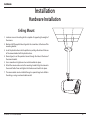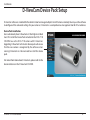
1
Preface Preface D-Link reserves the right to revise this publication and to make changes in the content hereof without obligation to notify any person or organization of such revisions or changes. Manual Revisions Revision Date 1.0 March 7, 2011 Description DCS-7110 Revision A1 with firmware version 1.00 Trademarks D-Link and the D-Link logo are trademarks or registered trademarks of D-Link Corporation or its subsidiaries in the United States or other countries. All other company or product names mentioned herein are trademarks or registered trademarks of their respective companies. Copyright © 2011 by D-Link Systems, Inc. All rights reserved. This publication may not be reproduced, in whole or in part, without prior expressed written permission from D-Link Systems, Inc. D-Link DCS-7110 User Manual 2 Preface Table of Contents Preface..........................................................................................2 Manual Revisions................................................................... 2 Trademarks.............................................................................. 2 Product Overview.......................................................................5 Package Contents.......................................................................... 5 System Requirements.................................................................. 5 Introduction.................................................................................... 6 Features............................................................................................. 7 Hardware Overview...................................................................... 8 Front Panel............................................................................... 8 Cable Connectors.................................................................. 9 Installation................................................................................ 10 Hardware Installation.................................................................10 Ceiling Mount.......................................................................10 Wall Mount.............................................................................11 Cable Connections......................................................................12 Software Installation..................................................................13 Setup Wizard.........................................................................13 Configuration........................................................................... 19 Web-based Configuration Utility...........................................19 Live Video.......................................................................................20 Client Setup...................................................................................24 D-Link DCS-7110 User Manual Setup................................................................................................25 Basic Setup.............................................................................25 Advanced Setup...................................................................26 System Overview.........................................................................27 Video........................................................................................28 Video Settings...................................................................28 Image Settings..................................................................31 Day and Night Settings..................................................33 Network...................................................................................34 IP Settings...........................................................................34 Port and Access Name Settings..................................37 Dynamic DNS....................................................................39 HTTPS...................................................................................40 Access List...........................................................................42 Advanced Settings..........................................................44 Event Management............................................................48 Motion Detection............................................................48 Tamper Detection............................................................49 DI and DO...........................................................................50 Event Settings...................................................................51 Recording...............................................................................57 Recording Settings..........................................................57 PTZ Control............................................................................59 Digital PTZ..........................................................................59 Mechanical PTZ................................................................60 3 Preface User Customization.............................................................62 Live Video Page Configuration....................................62 HTML Code Examples....................................................63 System.....................................................................................64 User Settings.....................................................................64 Device Settings.................................................................65 Time and Date...................................................................66 Maintenance......................................................................67 Parameter List...................................................................69 Logs......................................................................................70 Technical Specifications......................................................... 71 Contacting Technical Support............................................... 73 Warranty.................................................................................... 74 Registration.............................................................................. 80 D-Link DCS-7110 User Manual 4 Product Overview Product Overview Package Contents DCS-7110 HD IR Outdoor Camera Mounting Bracket Power Adapter CAT5 Ethernet Cable User Manual and Software on CD-ROM Quick Install Guide Note: Using a power supply with a different voltage than the one included with the package will cause damage and void the warranty for this product. If any of the above items are missing, please contact your reseller. System Requirements Operating System: Microsoft Windows® 7, Vista®, or XP Memory: At least 256MB of RAM (512MB recommended) Web Browser: Internet Explorer 6.x or higher VGA card resolution: SVGA or XGA (1024x768 or above) CPU: 1.7GHz or above (2.8GHz plus processor with 512MB memory and a 32MB video card is required for multiple camera viewing and recording in IP surveillance program) An available Ethernet connection D-Link DCS-7110 User Manual 5 Product Overview Introduction D-Link DCS-7110 is an all-in-one, outdoor network camera equipped with industry-leading high definition (HD) megapixel resolution and H.264 compression. The DCS-7110 connects to a network to provide high-quality live video over the Internet. This camera is capable of capturing video in both dark and light environments thanks to its built-in IR LEDs and IR-cut removable (ICR) filter. The ICR filter can be manually applied via the web, or set to automatically adjust based on lightning conditions. This feature allows the camera to capture crisp color images during the daytime and detailed grayscale images at night or in or low-light conditions. Note: Use of audio or video equipment for recording the image or voice of a person without their knowledge and consent is prohibited in certain states or jurisdictions. Nothing herein represents a warranty or representation that the D-Link product provided herein is suitable for the end-user’s intended use under the applicable laws of his or her state. D-Link disclaims any liability whatsoever for any end-user use of the D-Link product, which fails to comply with applicable state, local, or federal laws. D-Link DCS-7110 User Manual 6 Product Overview Features Flexible Connectivity The DCS-7110 includes input and output ports for connectivity to external devices such as IR sensors, switches, and alarm relays. It also comes with an RS-485 interface, providing connectivity to an optional pan/tilt scanner. The DCS-7110 also incorporates Power over Ethernet (PoE), allowing it to be easily installed in a variety of locations without the need for supplemental power cabling. High-Quality Video at HD Resolution The DCS-7110 provides real-time video feeds at up to 30 fps with HD resolution. H.264 encoding ensures that images remain crisp, clear, and vivid without taking up too much network bandwidth. Weather-proof with Tamper Detection Designed to be mounted outdoors, the DCS-7110 includes an IP66 certified enclosure which protects against the elements. Anti-tamper features make this camera suitable for tamper-prone locations such as transportation hubs, schools, or correctional facilities. The electronic tamper detection system can sense whenever the camera has been redirected, de-focused, blocked, or spray-painted, and respond promptly with a visible or audible alarm. Advanced Web User Interface The DCS-7110 features D-Link’s latest-generation graphical user interface. This freshly-designed web interface features a clean, compact, and professional home screen which dramatically increases usability. Menu navigation is simplified thanks to a tree view which logically groups functions, helping users to quickly find what they need. Likewise, intuitive graphic icons reduce the amount text and clutter within the browser window. New users will appreciate the convenient contextual help which offers an easy way to find assistance with camera management tasks. 3GPP Mobile Surveillance Support for 3GPP Mobile Surveillance allows users to view a live video feed from a 3GPP compatible Internet-ready mobile device. This extends monitoring capability, allowing users to check the camera’s video feed while on the go without a computer. D-Link DCS-7110 User Manual 7 Product Overview Hardware Overview Front Panel Sunshield Adjustable sunshield protects the camera sensor from direct sunlight Infrared LEDs IR LEDs Illuminate the camera's field of view IR-Cut Removable (ICR) Sensor IR-Cut Removable sensor judges lighting conditions and switches from day mode to night mode accordingly D-Link DCS-7110 User Manual 8 Product Overview Cable Connectors Ethernet (PoE) RJ-45 connector is for Ethernet and can also be used to power the camera using PoE DC Power Connects to the 12 V DC power adapter to power the camera Reset Button Press and hold this button for 10 seconds to reset the camera to the factory default settings AC & RS-485 Connectors 24 V AC power wiring can be connected to the AC connectors to power the camera. An RS-485 scanner can be connected to the RS-485 connectors for mechanical pan and tilt controls. DI/DO Connectors DI/DO connectors provide a physical interface to send and receive digital signals to and from a variety of external devices D-Link DCS-7110 User Manual 9 Installation Installation Hardware Installation Ceiling Mount 1. Locate an area on the ceiling which is capable of supporting the weight of the camera. 2. Mark and drill three pilot holes aligned to the screw holes at the base of the mounting bracket. 3. Insert the plastic anchors into the pilot holes, and align the holes at the base of the camera bracket with the plastic anchors. 4. Once aligned, insert the provided screws through the holes at the base of the camera bracket. 5. Use a screwdriver to tighten and secure the bracket into place. 6. Attach the camera enclosure to the mounting bracket. Align the camera to the correct field of view and tighten the thumbscrew to lock it into place. 7. The camera cables can be installed through a separate large hole drilled in the ceiling, or using an external cable conduit. D-Link DCS-7110 User Manual 10 Installation Wall Mount 1. Locate an area on the wall which is capable of supporting the weight of the camera. 2. Mark and drill three pilot holes aligned to the screw holes at the base of the mounting bracket. 3. Insert the plastic anchors into the pilot holes, and align the holes at the base of the camera bracket with the plastic anchors. 4. Once aligned, insert the provided screws through the holes at the base of the camera bracket. 5. Use a screwdriver to tighten and secure the bracket into place. 6. Attach the camera enclosure to the mounting bracket. Align the camera to the correct field of view and tighten the thumbscrew to lock it into place. 7. The camera cables can be installed through a separate large hole drilled in the wall, or using an external cable conduit. D-Link DCS-7110 User Manual 11 Installation Cable Connections Basic Connection (without PoE) 1. Connect the camera to your switch or router via Ethernet cable. 2. Connect the power cable from the camera to the supplied power adapter. 3. Connect the supplied power adapter to a power outlet. Connection Using a PoE Switch If using a PoE switch or router, connect the network camera via Ethernet cable. PoE will transmit both power and data over a single cable. Note: Once power has been established, the LED will turn red. When the device has obtained an IP address and is accessible, the LED will turn green. D-Link DCS-7110 User Manual 12 Installation Software Installation Setup Wizard Insert the DCS-7110 CD into your computer's CD-ROM drive to begin the installation. If the Autorun function on your computer is disabled, or if the D-Link Launcher fails to start automatically, click Start > Run. Type D:\autorun.exe, where D: represents the drive letter of your CD-ROM drive. Click Setup Wizard to begin the installation. After clicking Setup Wizard, the window on the right will open. Click Next to continue. D-Link DCS-7110 User Manual 13 Installation Click Yes to accept the License Agreement. To start the installation process, click Next. Note: The installation may take several minutes to finish. D-Link DCS-7110 User Manual 14 Installation Click Finish to complete the installation. Click on the D-Link Setup Wizard SE icon that was created in your Windows Start menu. Start > D-Link > Setup Wizard SE D-Link DCS-7110 User Manual 15 Installation The Setup Wizard will appear and display the MAC address and IP address of your camera(s). If you have a DHCP server on your network, a valid IP Address will be displayed. If your network does not use a DHCP server, the network camera's default static IP address 192.168.0.20 will be displayed. Click the Wizard button to continue. Enter the Admin ID and password. When logging in for the first time, the default Admin ID is admin with the password left blank. Click Next to proceed to the next page. D-Link DCS-7110 User Manual 16 Installation Select DHCP if your camera obtains an IP address automatically when it boots up. Select static IP if the camera will use the same IP address each time it is started. Click Next to proceed to the next page. Take a moment to confirm your settings and click Restart. D-Link DCS-7110 User Manual 17 Installation D-ViewCam Device Pack Setup D-ViewCam software is included for the administrator to manage multiple D-Link IP cameras remotely. You may use the software to configure all the advanced settings for your cameras. D-ViewCam is a comprehensive management tool for IP surveillance. Device Pack Installation Users who already have D-ViewCam v3.10 or higher installed must first install the Device Pack included on the DCS-7110 CD-ROM to use the DCS-7110 camera with D-ViewCam. Upgrading D-ViewCam to the latest device pack will ensure that the new camera is recognized by the software. Users running D-ViewCam v3.2 do not need to install this device pack. For more information about D-ViewCam, please refer to the documentation on the D-ViewCam CD-ROM. D-Link DCS-7110 User Manual 18 Configuration Configuration Web-based Configuration Utility This section will show you how to configure your new D-Link Network Camera using the Web-based Configuration Utility. To access the configuration utility, open a web-browser such as Internet Explorer and enter the IP address for your Network Camera (http://192.168.1.179). Note: For example, the address is 192.168.1.179. Your address may differ. Enter Admin for the username and then leave the password blank by default. Click OK to continue. D-Link DCS-7110 User Manual 19 Configuration Live Video When you connect to the camera's web interface you will see the following page. This is the Live Video page which will allow you to view the camera's video feed and control basic camera functions using the icons on the screen. Please refer to the tables on the following pages for detailed information about the icons on this screen. D-Link DCS-7110 User Manual 20 Configuration D-Link Logo Click this logo to visit the D-Link website. The logos and website can be customized to fit your needs. For more information, please refer to User Customization on page 62. Securicam Logo Client Settings Language Setup Setup the stream transmission mode and saving options on the local computer. Select this option to adjust the language settings. Click on the setup icon on the main page to enter the camera setting pages. Note that only Administrators can access the setup page. Two types of user interfaces are available: Advanced Setup for professional users and Basic Setup for entry-level users. Click this button to turn the digital output device on or off. Digital Output Video Stream Global View This camera supports multiple streams (stream 1 ~ 4) simultaneously. You may select one for live viewing. Click on this item to display the Global View window. The Global View window contains a full view image (the largest frame size of the captured video) and a floating frame (the viewing region of the current video stream). The floating frame allows users to control the e-PTZ function (Electronic Pan/Tilt/Zoom). For more information about e-PTZ operation, please refer to PTZ Control on page 21. For more information about how to set up the viewing region of the current video stream, please refer to Video settings on page 28. D-Link DCS-7110 User Manual 21 Configuration This camera supports both “digital“ (e-PTZ) and “mechanical“ pan/tilt/ zoom control. Please refer to PTZ Control for detailed information. Digital PTZ Control Panel Mechanical PTZ Control Panel* Mechanical PTZ: Connect the camera to a PTZ driver or scanner via RS-485 interface. PTZ Control Digital PTZ: Control the e-PTZ operation. It allows users to quickly move the focus to a target area for close-up viewing without physically moving the camera. Home: Move the camera to the preset home position. ePT Direction Direction: Control the camera’s pan or tilt directions (up/down/left/ right). Control camera focus to get a clear image. (Available only under mechanical PTZ mode*) Focus Focus Near Focus Far Zoom in/out to magnify or shrink the digital image. Zoom in: Magnify image Zoom Patrol Auto Pan Go Preset Speed Control Zoom out: Diminish image Patrol: Patrol executes a pre-defined sequence of pan, tilt, zoom, and focus features Before selecting this, users must define at least two preset points. Auto Pan: Auto Pan automatically scans an area horizontally. Select from the preset drop-down list to quickly move the camera to the desired preset position. Control Pan/Tilt/Zoom speed Pan Speed Control Tilt Speed Control Zoom Speed Control *See Mechanical PTZ on page 61 for more information about the installation of a PTZ scanner. D-Link DCS-7110 User Manual 22 Configuration Snapshot Recording Recording Folder Digital Zoom Full Screen Zoom ratio Help Click this button to capture and save still images. The captured images will be displayed in a pop-up window. Right-click the image and select Save Picture As to save it in JPEG (*.jpg) or BMP (*.bmp) format. Click this button to record video clips to your computer. When you exit the web browser, video recording stops. Specify a storage destination for the recorded video files. Uncheck Disable digital zoom to enable the zoom operation. The navigation screen indicates the part of the image being magnified. To control the zoom level, drag the slider bar. To move to a different area you want to magnify, drag the navigation screen. Click this button to switch to full screen mode. Press the Esc key to switch back to normal mode. Auto: The video zoom ratio will be changed automatically according to viewing window size. 100%: Keep the video zoom ratio at 100% 50%: Keep the video zoom ratio at 50% 25%: Keep the video zoom ratio at 25% Click the Help button to learn the detailed information regarding camera setup and solve any problems you encounter. D-Link DCS-7110 User Manual 23 Configuration Client Setup Click on the Client Settings button to bring you to the following screen which allows you to configure the basic protocol options for you camera. H.264/MPEG4 Protocol Options For additional information about streaming options please refer to page 31. UDP Unicast: Stream to a single computer. UDP Multicast: Stream to multiple computers. TCP: Provides higher quality video streaming than UDP and provides error correction. However, transmission speed will be reduced. HTTP: Offers the highest image and video quality. However, packet loss will diminish image quality when bandwidth becomes restricted. If the network is protected by a firewall and it opens only HTTP port (80), HTTP protocol must be selected. In this mode, audio is disabled and only video can be viewed. UDP connections will not be available to remote users if all four ports have not been forwarded. Only the HTTP port must be forwarded for remote users to make an HTTP connection (video only). MP4 Saving Options Folder: Select the folder where you would like the MP4 file saved on your computer. File name prefix: Enter a file name prefix for the MP4 files. Add date and time suffix to file name: Select this checkbox if you would like the date and time to be added to the end of each filename. Local Streaming Buffer Time Enter the buffer time in milliseconds. The buffer will cause a slight delay between live activity and the video of the live stream but may increase the quality of video. D-Link DCS-7110 User Manual 24 Configuration Setup The DCS-7110 includes basic and advanced setup screens. Both screens include a tree view with multiple setup options. This manual includes detailed explanations for all advanced setup screens. Basic Setup Click the setup button to enter the setup screen. Click on the basic button to enter the setup screen. Please click the [+] next to each folder to view the options. Basic setup includes the following options: System Overview Video - Video Settings Network - IP Settings Event Management - Motion Detection, Tamper Detection PTZ Control - Digital PTZ System - User Settings, Device Settings, Time and Date, Maintenance D-Link DCS-7110 User Manual 25 Configuration Advanced Setup Click the Setup button to enter the setup screen. Click on the Advanced button to enter the setup screen. Please click the [+] next to each folder to view the options. Advanced setup includes the following options: System Overview Video - Video Settings, Image Settings, Day and Night Settings Network - IP Settings, Port & Access Name Settings, Dynamic DNS, HTTPS, Access List, Advanced Settings Event Management - Motion Detection, Tamper Detection, DI and DO, Event Settings Recording - Recording Settings PTZ Control - Digtal PTZ, Mechanical PTZ User Customization - Live Video Page Config, HTML Code Examples System - User Settings, Device Settings, Time and Date, Maintenance, Parameter List, Logs D-Link DCS-7110 User Manual 26 Configuration System Overview The system overview page contains a summary of the camera's current settings. For more information about adjusting these settings, please consult the subsequent instructions found in this manual. D-Link DCS-7110 User Manual 27 Configuration Video Video Settings This page allows you to set up 4 video streams to be displayed on a computer, mobile device, or storage system. Each stream has independent options for proper compression type, frame size, frame rate to optimize the bandwidth utilization and video quality. Video Options Viewing Window: The camera supports multiple streams with frame size ranging from 176 x 144 to 1280 x 800. Click Viewing Window to open the viewing region setting page. On this page, you can set the Region of Interest (ROI) and the Output Frame Size for stream 1~3. Please follow the steps below to set up a stream: 1. Select a stream whose viewing region you would like to set. 2. Select a Region of Interest from the drop-down list, the floating frame will resize accordingly. If you want to set up a customized viewing region, you can also resize and drag the floating frame to a desired position with your mouse. 3. Choose a proper Output Frame Size from the drop-down list according to the size of your monitoring device. Note: All the items in the “Output Frame Size” should not be greater than the “Region of Interest “(current maximum resolution). The definition of multiple streams: Stream 1-3: Users can define the "Region of Interest" (viewing region) and the "Output Frame Rate" (size of the live view window). Stream 4: This is global view stream which captures the full view of the video. Users can also define the "Output Frame Rate" (size of the live view window). D-Link DCS-7110 User Manual 28 Configuration Once finished with the setting in the Viewing Window, click Save to enable the settings and click Close to exit the window. The selected Output Frame Size will immediately be applied to the Frame size of video stream. You can then go back to the Live Video to test the new settings. Sensor Setting: Click Sensor Setting to open the Sensor Setting page. On this page, you can set the maximum exposure time, exposure level, and AGC (Auto Gain Control) setting. You can configure two sets of sensor setting: one for normal situations, the other for special situations, such as day/night/schedule mode. Exposure • Maximum Exposure Time: Select a proper maximum exposure time according to the light source of the surroundings. Shorter exposure times result in less light reaching the sensor. The exposure times are selectable for the following durations: 1/30 second, 1/15 second, and 1/5 second. • Exposure level: You can manually set the Exposure level which ranges from 1 to 8 (dark to bright). • Max. Gain (Auto Gain Control): You can manually set the AGC level (2X 4X, or 8X). The higher the value, the brighter the image will be. • Enable BLC (Back Light Compensation): Enable this option when the object is too dark or too bright to recognize. It allows the camera to adjust to the best light conditions in any environment and automatically give the necessary light compensation. You may click Preview to fine-tune the image, or click Restore to recall the original setting without incorporating the changes. When completed with the setting on this page, click Save to enable the setting and click Close to exit the page. If you want to configure another sensor setting for day/night/schedule mode, please click Profile 2 and follow the steps below to setup: 1.Click Enable this profile. 2.Select the applied mode: Day mode, Night mode, or schedule mode. Please manually enter a range of time if you choose Schedule mode. 3.Configure Exposure setting in the second column. 4.Click Save to enable the setting and click Close to exit the page. D-Link DCS-7110 User Manual 29 Configuration Video Quality Setting for Stream 1~4 Compression Type: The compression level affects the amount of bandwidth and storage required. Lower compression uses more bandwidth and storage but delivers better image quality. Of the three options, H.264 consumes much less network bandwidth compared to MPEG4 and JPEG. Frame Size: Select proper frame size for different viewing devices, bigger frame size requires more bandwidth and storage usage. For smaller viewers, such as mobile phones, a smaller frame size and lower frame rate is recommended. There are 5 options you can select: 176x144, 320x240, 640x480, 1280x720 and 1280x800, if there is no viewing window applied. (176x144 for mobile phone, 640x480 for VGA display, 1280x720 for HD display). Frame Rate: This option affects the smoothness of the video. Select higher frame rate for smoother video quality but it requires more storage usage. 10 options for selection: customize, 1, 3, 5, 8, 10, 15, 20, 25, 30 fps (30 fps is recommended real-time video on a computer monitor. 5 fps is ideal for mobile viewers). Intra Frame Period: Determines the frequency and I frame is planted. The shorter the duration, the more likely you will get better video quality, but at the cost of higher network bandwidth consumption. Select the intra frame period from the following durations: 1/4 second, 1/2 second, 1 second, 2 seconds, 3 seconds and 4 seconds. Video Quality: This setting limits the maximum refresh frame rate. • Constant bit rate: To set a fixed bandwidth regardless of the video quality, select Constant bit rate and the desired bandwidth from 20 Kbps to 8 Mbps. You can also select Customize and manually enter a value. • Fixed quality: To optimize the bandwidth utilization and video quality. The video quality can be adjusted to the following setting: Medium, Standard, Good, Detailed and Excellent. You can also select Customize and manually enter a value. D-Link DCS-7110 User Manual 30 Configuration Image Settings This page allows you to tune the white balance, brightness, saturation, contrast, and sharpness settings for the video. Color: Select either a Color or B/W (black and white, monochrome) video display. Power Line Frequency: Select either 50 or 60 Hz depending on your region. Video Orientation: Flip will vertically rotate the video. Mirror will horizontally rotate the video. You may select both options if camera is being installed upside down. White Balance: This adjusts the relative amount of red, green and blue primary colors in the image so that the neutral colors are reproduced correctly. • Auto: The camera automatically adjusts the color temperature of the light in response to different light sources. The white balance setting defaults to Auto and works well in most situations. • Fixed: Follow the steps below to manually set the white balance to compensate for the ambient lighting conditions. 1. Set the White balance to Auto and click Save. 2. Place a sheet of white paper in front of the lens, then allow the camera to adjust the color temperature automatically. 3. Select Fixed to confirm the setting while the white balance is being measured. 4. Click Save to enable the new setting. Brightness: Adjust the image brightness level, which ranges from -5 to +5 Saturation: Adjust the image saturation level, which ranges from -5 to +5 Contrast: Adjust the image contrast level, which ranges from -5 to +5 D-Link DCS-7110 User Manual 31 Configuration Sharpness: Adjust the image sharpness level, which ranges from -3 to +3 Overlay Title and Time Stamp on Video: Select this option to place the video title and time on the video streams. (When the frame size is set to 176 x 144 only the time will be stamped on the video streams.) Privacy Mask: In this page, you can block out certain sensitive zones for privacy concerns. To set up a Privacy Mask Window, follow the steps given below: 1. Click New to add a window. 2. The height and width of the window can be resized and drag-dropped. 3. Enter a Window Name and click Save to apply changes. 4. Select Enable privacy mask to facilitate this function. None: • Up to 5 privacy mask windows can be set up on the same screen. • If you want to delete the privacy mask window, please click the ‘x’ at the upper right-hand corner of the window. D-Link DCS-7110 User Manual 32 Configuration Day and Night Settings Switch to B/W in Night Mode: Select to automatically enable the camera to switch to B/W night mode. IR Cut Filter: The IR-Cut Removable (ICR) filter mechanically switches between two different sensor filters. It provides the best light conditions both during the day and night. The following options are: • Auto Mode: The camera automatically switches between day and night mode by judging the level of ambient light. This mode is accessible only when the exposure mode is set to Auto. • Day Mode: In this mode the camera switches on the IR cut filter at all times, which will block the infrared light from reaching the sensor so that the colors are not distorted. • Night Mode: The camera switches off the IR cut filter to allow the infrared light to pass through. This helps the camera to see more clearly in low light conditions. • Synchronize with Digital Input: The camera automatically removes the IR cut filter when DI triggers. • Schedule Mode: The camera switches between day and night mode based on a specific schedule. Ensure to enter the starting and ending time for the day mode. Note that the time format is [hh:mm] and is expressed in 24-hour clock time. By default, the starting time and ending time of day mode are set to 07:00 and 18:00. Light Sensor Sensitivity: Select Low, Normal, or High sensitivity for the light sensor. Disable IR LED: Select this box to disable the IR LED. The IR LED automatically switches on at night. By default the LED automatically switches on at night. D-Link DCS-7110 User Manual 33 Configuration Network IP Settings IPv4 LAN: Select this option when the camera is deployed on a local area network (LAN) and is intended to be accessed by local computers. The default setting for the Network Type is LAN. Remember to click Save when you complete the Network setting. • Get IP address automatically (DHCP): Select this connection if you have a DHCP server running on your network and would like a dynamic IP address to be assigned to the camera automatically. • Use fixed IP address: You may enter a static or fixed IP address for your camera. IP Address: Enter an IP address. Subnet Mask: The default value is “255.255.255.0.” This helps to determine if the designated IP address is on the same subnet. Default Router: This is the gateway used to forward frames to destinations in a different subnet. (Invalid router setting will cause the transmission to fail if its destination is in a different subnet). Primary DNS: The Primary Domain Name Server (DNS) that translates hostname into IP address. Secondary DNS: Secondary Domain Name Server (DNS) that backups the Primary DNS. Primary WINS Server: The primary WINS server that maintains the database of computer name and IP address. Secondary WINS Server: The secondary WINS server that maintains the database of computer name and IP address. D-Link DCS-7110 User Manual 34 Configuration • Enable UPnP Presentation: Select this option to enable UPnP presentation for the camera so that whenever a camera is presented to the LAN, shortcuts of connected cameras will be listed in My Network Places. You can click the shortcut to link to the web browser. Currently, UPnP is supported by Windows XP or later. Note that to utilize this feature, please make sure the UPnP component is installed on your computer. • Enable UPnP Port Forwarding: To access the camera from the Internet, select this option to allow the camera to open ports on the router automatically so that video streams can be sent out from a LAN. To utilize this feature, make sure that your router supports UPnP and it is activated. How does UPnP work? UPnP networking technology provides automatic IP configuration and dynamic discovery of devices added to a network. Services and capabilities offered by networked devices, such as printing and file sharing, are available among each other without bothersome network configuration. In the case of Network Cameras, you will see Network Camera shortcuts at My Network Places. PPPoE: Select this option to configure the camera to make it accessible from anywhere with an Internet connection. Note that to utilize this feature, it requires an account provided by your ISP. Follow the steps below to acquire the camera’s public IP address. 1. Set up the camera on the LAN 2. Go to Live View > Setup > Event management > Event settings > Server Settings (please refer to Server Settings to add a new e-mail or FTP server) 3. Go to Setup > Event management > Event settings > Media Settings (please refer to Media Settings). Select System log so that you will receive the system log in TXT file format which contains the camera’s public IP address in your e-mail or on the FTP server. 4. Go to Setup > Network > IP settings. Select PPPoE and enter the user name and password provided by your ISP. Click Save to enable the setting. 5. The camera will reboot. 6. Disconnect the power to the camera. Remove it from the LAN environment. D-Link DCS-7110 User Manual 35 Configuration IPv6 Enable IPv6: Select this option and click Save to enable IPv6 setting. Please note that this only works if your network environment and hardware equipment support IPv6. The browser should be Microsoft® Internet Explorer 6.5, Mozilla Firefox 3.0 or above. When IPv6 is enabled, by default, the camera will listen to router advertisements and be assigned a link-local IPv6 address accordingly. IPv6 Information: Click this button to obtain the IPv6 information. If your IPv6 setting are successful, the IPv6 address list will be listed in the pop-up window. Please follow the steps below to link to an IPv6 address: 1. Open your web browser. 2. Enter the link-global or link-local IPv6 address in the address bar of your web browser. 3. Press Enter on the keyboard or click Refresh button to refresh the webpage. Manually Setup the IP Address: Select this option to manually configure IPv6 setting if your network environment does not have DHCPv6 server and advertisementsenabled routers. D-Link DCS-7110 User Manual 36 Configuration Port and Access Name Settings HTTPS By default, the HTTPS port is set to 443. It can also be assigned to another port number between 1025 and 65535. FTP The FTP server allows the user to save recorded video clips. You can utilize D-Link's IP Cam Wizard to upgrade the firmware via FTP server. By default, the FTP port is set to 21. It also can be assigned to another port number between 1025 and 65535. HTTP By default, the HTTP port is set to 80 and the secondary HTTP port is set to 8080. They can also be assigned to another port number between 1025 and 65535. Authentication: Depending on your network security requirements, the camera provides two types of security setting for an HTTP transaction: basic and digest. If basic authentication is selected, the password is sent in plain text format and there can be potential risks of being intercepted. If digest authentication is selected, user credentials are encrypted using MD5 algorithm and thus provide better protection against unauthorized accesses. Access name for stream 1 ~ 5: The Network camera supports multiple streams simultaneously. The access name is used to differentiate the streaming source. Users can click Setup > Video > Video Settings to set up the video quality of linked streams. RTSP To utilize RTSP streaming authentication, make sure that you have set a password for the camera first. Please refer to User Settings for details. Authentication: Depending on your network security requirements, the camera provides three types of security setting for streaming via RTSP Protocol: disable, basic, and digest. If basic authentication is selected, the password is sent in plain text format, but there can be potential risks of it being intercepted. If digest authentication is selected, user credentials are encrypted using MD5 algorithm, thus providing better protection against unauthorized access. D-Link DCS-7110 User Manual 37 Configuration Access Name for Stream 1 ~ 5: This camera supports multiple streams simultaneously. The access name is used to differentiate the streaming source. If you want to use an RTSP player to access the camera, you have to set the video mode to H.264 / MPEG-4 and use the following RTSP URL command to request transmission of the streaming data. Multicast and Unicast Streaming Protocols You may choose to enable multicast or unicast for your camera audio and video streaming so that your cameras (sources) and the receivers (clients) can establish the connection to send and receive contents. Unicast video transmission delivers a stream through point-to-point transmission. Multicast, on the other hand, sends a stream to the multicast group address and allows multiple clients to acquire the stream at the same time by requesting a copy from the multicast group address. Therefore, enabling multicast can effectively save network bandwidth. An IP Multicast group address is used to send and receive content. Sources use this group address as the destination address while sending their data packets. Receivers use this group address to inform the network that they are interested in receiving packets sent to that group. The ports can be changed to values between 1025 and 65535. The multicast RTP port must be an even number, and the multicast RTCP port number is the multicast RTP port number plus one, and thus is always odd. When the multicast RTP port changes, the multicast RTCP port will change accordingly. Multicast TTL [1~255]: The multicast TTL (Time To Live) is the value that tells the router the range a packet can be forwarded. Click the items to display the detailed configuration information. Select the Always multicast option to enable multicast for stream 1 ~ 4. D-Link DCS-7110 User Manual 38 Configuration Dynamic DNS This section explains how to configure the dynamic domain name service for the camera. DDNS is a service that allows your camera, especially when assigned with a dynamic IP address, to have a fixed host and domain name. Enable DDNS: Select this option to enable the DDNS setting. Server Name: Select a DDNS server name from the provider drop-down list. With a Dynamic DNS account, the camera automatically updates your IP address. To enable DDNS, enter your host information. Click Next to continue. Host Name: Enter the host name of the DDNS server. Username: Enter your username or e-mail used to connect to the DDNS Password: Enter your password used to connect to the DDNS server. Status: Indicate the connection status, automatically determined by the system. D-Link DCS-7110 User Manual 39 Configuration HTTPS This section explains how to enable authentication and encrypted communication over SSL (Secure Socket Layer). It helps protect streaming data transmission over the Internet on higher security level. Enable HTTPS Select this item to enable HTTPS communication, then select a connection option: "HTTP & HTTPS" or "HTTPS only". Note that you have to create and install a certificate first in the second column before clicking the Save button. Create and Install Certificate Method Before using HTTPS for communication with the camera, a certificate must be created first. There are three ways to create and install a certificate: Create Self-signed Certificate Automatically 1. Select this option. 2. In the first column, select Enable HTTPS secure connection, then select a connection option: “HTTP & HTTPS” or “HTTPS only”. 3. Click Save to generate a certificate. 4. The Certificate Information will automatically be displayed in the third column. You can click Property to view detailed information about the certificate. 5. Click Live Video to return to the main page. Change the address from “http://” to “https://“ in the address bar and press Enter. Some Security Alert dialogs will pop up. Click OK or Yes to enable HTTPS. Create Self-signed Certificate Manually 1. Click Create to open the Create Certificate page, then click Save to generate the certificate. 2. The Certificate Information will automatically be displayed in the third column as shown below. You can click Property to see detailed information about the certificate. D-Link DCS-7110 User Manual 40 Configuration Create Certificate Request and Install Select this option to create a certificate from a certificate authority. 1. Click Create to open the Create Certificate page, then click Save to generate the certificate. 2. If you see the information bar, click OK and click on the Information bar at the top of the page to allow pop-up. 3. The pop-up window shows an example of a certificate request. 4. Look for a trusted certificate authority that issues digital certificates. Enroll the camera. Wait for the certificate authority to issue a SSL certificate. Click Browse... to search for the issued certificate, then click Upload in the second column. How do I cancel the HTTPS setting? 1. Deselect Enable HTTPS secure connection in the first column and click Save. A warning dialog will pop up. 2. Click OK to disable HTTPS. 3. The webpage will redirect to a non-HTTPS page automatically. If you want to create and install other certificates, please remove the existing one. To remove the signed certificate, deselect Enable HTTPS secure connection in the first column and click Save. Then click Remove to erase the certificate. D-Link DCS-7110 User Manual 41 Configuration Access List This section explains how to control access permissions by verifying the connecting client PC’s IP address. General Settings Maximum number of concurrent streaming connection(s) limited to: Simultaneous live viewing for 1~10 clients (including stream 1 ~ stream 5). The default value is 10. If you modify the value and click Save, all current connections will be disconnected and automatically attempt to re-link (I.E. Explorer or Quick Time Player). View Information: Click this button to display the connection status window showing a list of the current connections. • IP address: Current connections to the camera. • Elapsed time: How much time the client has been at the webpage. • User ID: If the administrator has set a password for the webpage, the clients have to enter a user name and password to access the live video. The user name will be displayed in the User ID column. If the administrator allows client to link to the webpage without a user name and password, the User ID column will be empty. There are some situations which allow clients access to the live video without a user name and password: 1. The administrator did not set up a user password. For more information about how to set up a user password and manage user accounts, please refer to User settings. 2. The administrator has set up a user password, but set RTSP Authentication to “disable“. For more information about RTSP Authentication, please refer to RTSP Streaming. D-Link DCS-7110 User Manual 42 Configuration • Refresh: Click this button to refresh all current connections. • Add to deny list: You can select entries from the Connection Status list and add them to the Deny List to deny access. Please note that the selected connections will only be disconnected temporarily and will automatically try to re-link again (IE Explore or Quick Time Player). If you want to enable the denied list, please select Enable access list filtering and click Save in the first column. Disconnect: If you want to break off the current connections, please select them and click this button. Please note that those selected connections will only be disconnected temporarily and will automatically try to re-link again (IE Explore or Quick Time Player). Enable Access List Filtering: Select this item and click Save if you want to enable the access list filtering function. Filter Type Select Allow or Deny as the filter type. If you choose Allow Type, only those clients whose IP addresses are on the Access List below can access the camera, and the others cannot access. On the contrary, if you choose Deny Type, those clients whose IP addresses are on the Access List below will not be allowed to access the camera, and the others can access. Filter Then you can add a rule to the following Access List. Please note that the IPv6 access list column will not be displayed unless you enable IPv6 on the Network page. For more information about IPv6 Setting, please refer to Enable IPv6 for detailed information. There are three types of rules: Single: This rule allows the user to add an IP address to the Allowed/Denied list. Network: This rule allows the user to assign a network address and corresponding subnet mask to the Allow/Deny List. Range: This rule allows the user to assign a range of IP addresses to the Allow/Deny List (This rule is only applied to IPv4). Administrator IP address Always allow the IP address to access this device: You can select this item and add the Administrator’s IP address in this field to make sure the Administrator can always connect to the device. D-Link DCS-7110 User Manual 43 Configuration Advanced Settings SNMP configuration This section explains how to use the SNMP on the network camera. The Simple Network Management Protocol is an application layer protocol that facilitates the exchange of management information between network devices. It helps network administrators to remotely manage network devices and find, solve network problems with ease. The SNMP consists of the following three key components: 1. Manager: Network-Management Station (NMS), a server which executes applications that monitor and control managed devices. 2. Agent: A network-management software module on a managed device which transfers the status of managed devices to the NMS. 3. Managed device: A network node on a managed network. For example: routers, switches, bridges, hubs, computer hosts, printers, IP telephones, network cameras, web server, and database. Before configuring SNMP setting on this page, please enable your NMS first. Enable SNMPv1, SNMPv2c: Select this option and enter the names of Read/Write community and Read Only community according to your NMS setting. Enable SNMPv3: This option contains cryptographic security, a higher security level which allows you to set the Authentication password and the Encryption password. • Security name: According to your NMS setting, choose Read/Write or Read Only and enter the community name. • Authentication type: Select MD5 or SHA as the authentication method. • Authentication password: Enter the password for authentication (at least 8 characters). • Encryption password: Enter a password for encryption (at least 8 characters). D-Link DCS-7110 User Manual 44 Configuration IEEE 802.1x Enable this function if your network environment uses IEEE 802.1x which is a portbased network access control. The network devices, intermediary switch/access point/hub, and RADIUS server must support and enable 802.1x setting. The 802.1x standard is designed to enhance the security of local area networks, which provides authentication to network devices (clients) attached to a network port (wired or wireless). If all certificates between client and server are verified, a point-to-point connection will be enabled. If authentication fails, access on that port will be prohibited. 802.1x utilizes an existing protocol, the Extensible Authentication Protocol (EAP), to facilitate communication. Please follow the steps below to enable 802.1x setting: 1. Before connecting the camera to the protected network with 802.1x, please apply a digital certificate from a Certificate Authority (ie. MIS of your company) which can be validated by a RADIUS server. 2. Connect the camera to a PC or notebook outside of the protected LAN. Open the configuration page of the camera as shown below. Select EAP-PEAP or EAP-TLS as the EAP method. In the following blanks, enter your ID and password issued by the CA, then upload related certificate(s). 3. When all setting are complete, move the camera to the protected LAN by connecting it to an 802.1x enabled switch. The devices will then start the authentication automatically. QoS (Quality of Service) Quality of Service refers to a resource reservation control mechanism, which guarantees a certain quality to different services on the network. Quality of service guarantees are important if the network capacity is insufficient, especially for realtime streaming multimedia applications. Quality can be defined as, for instance, a maintained level of bit rate, low latency, no packet dropping, etc. The following are the main benefits of a QoS-aware network: The ability to prioritize traffic and guarantee a certain level of performance to the data flow. D-Link DCS-7110 User Manual 45 Configuration The ability to control the amount of bandwidth each application may use, and thus provide higher reliability and stability on the network. Requirements for QoS: To utilize QoS in a network environment, the following requirements must be met: • All network switches and routers in the network must include support for QoS. • The network video devices used in the network must be QoS-enabled. CoS IEEE802.1p defines a QoS model at OSI Layer 2 (Data Link Layer), which is called CoS, Class of Service. It adds a 3-bit value to the VLAN MAC header, which indicates prioritization from 0~7 (Eight different classes of service are available). The priority is set up on the network switches, which then use different queuing disciplines to forward the packets. Please follow the steps below to enable CoS settings: 1. Click Enable CoS 2. Enter the VLAN ID of your switch (0~4095) 3. Choose the priority for each application (0~7). Note: • The VLAN Switch (802.1p) is required. The web browsing may fail if the CoS setting is incorrect. • Class of Service technologies do not guarantee a level of service in terms of bandwidth and delivery time. They only offer a "best-effort." Users can think of CoS as "coarsely-grained" traffic control and QoS as "finely-grained" traffic control. • Though CoS is simple to manage, it lacks scalability and does not offer end-to-end guarantees since it is based on L2 protocol. D-Link DCS-7110 User Manual 46 Configuration QoS/DSCP DSCP-ECN defines QoS at Layer 3 (Network Layer). The Differentiated Services (DiffServ) model is based on packet marking and router queuing disciplines. The marking is done by adding a field to the IP header, called the DSCP (Differentiated Services Code Point). This is a 6-bit field that provides 64 different class IDs. It gives an indication of how a given packet is to be forwarded, known as the Per Hop Behavior (PHB). The PHB describes a particular service level in terms of bandwidth, queuing theory, and dropping (discarding the packet) decisions. Routers at each network node classify packets according to their DSCP value and give them a particular forwarding treatment. For example, how much bandwidth should be reserved. Quality of Service refers to a resource reservation control mechanism, which guarantees a certain quality to different services on the network. Quality of service guarantees are important if the network capacity is insufficient, especially for real-time streaming multimedia applications. Quality can be defined as, for instance, a maintained level of bit rate, low latency, no packet dropping, etc. D-Link DCS-7110 User Manual 47 Configuration Event Management Motion Detection Motion can be detected by measuring change in speed or vector of an object or objects in the field of view. Enable Motion Detection: Select this option to turn on the motion detection feature. Window Name: Create your own name for the monitored area/ window. It will show at the top of the motion window. Sensitivity: Set the measurable difference between two sequential images that would indicate motion. Percentage: Set the amount of motion in the window being monitored that is required to trigger a motion detected alert. If this is set to 100%, this means that motion must be detected within the whole window to trigger a snapshot. Note: Setting a higher sensitivity and a lower percentage will make motion easier to be detected. New: Click to add a new window. A maximum of three motion windows can be opened simultaneously. Use your mouse to drag the window frame to resize or the title bar to move. Clicking on the ‘x’ at the upper right corner of the window will close the window. Save: Save the configured settings. To enable motion detection, follow the steps below: 1. Click New to add a new motion detection window. 2. Enter a name in the Window Name field. 3. Define the sensitivity to moving objects and the space ratio of all alerted pixels by moving the Sensitivity and Percentage slide bar. 4. Click Save to apply the changes. 5. Select Enable motion detection to activate motion detection. D-Link DCS-7110 User Manual 48 Configuration Tamper Detection With tamper detection, the camera is capable of detecting incidents such as redirection, blocking or de-focusing, or even spray paint. To enable tamper detection, follow the steps given below: 1. Select Enable camera tampering detection. 2. Enter the tamper trigger duration (10 sec. ~ 10 min.). The tamper alarm will be triggered only when the tampering factor (the difference between current frame and pre-saved background) exceeds the trigger threshold. Set up the event source as Camera Tampering Detection on Event Settings > Server Settings (how to send alarm message)/ Media Settings (send what type of alarm message)/Event Settings/. Please refer to Event settings for detailed information. D-Link DCS-7110 User Manual 49 Configuration DI and DO Network camera provides a general I/O terminal block with one digital input and digital output for device control. The I/O connector provides the physical interface for digital input (DI+. GND) and digital output (DO-, +12V) that is used for connecting a diversity of external alarm devices to the camera such as IR-Sensors and alarm relays. Once triggered images will be taken and e-mailed. DI/DO Schematics D-Link DCS-7110 User Manual 50 Configuration Event Settings This section explains how to configure the camera to respond to particular situations (event). A typical application is that when a motion is detected, the camera sends buffered images to an FTP server or e-mail address as notifications. Sever Settings Click Add Server on Event Settings page to open the Server Setting page. On this page, you can specify where the notification messages are sent when a trigger is activated. A total of 5 server settings can be configured. Name: Enter a name for the server setting. • Type: There are four choices of server types available: E-mail, FTP, HTTP, and Network storage. Select the item to display the detailed configuration options. You can configure either one or all of them. E-mail: Select to send the media files via e-mail when a trigger is activated. • Sender e-mail address: Enter the e-mail address of the sender. • Recipient e-mail address: Enter the e-mail address of the recipient. • Server address: Enter the domain name or IP address of the e-mail server. • User name: Enter the user name of the e-mail account if necessary. • Password: Enter the password of the e-mail account if necessary. • Server port: The default mail server port is set to 25. You can also manually set another port. If your SMTP server requires a secure connection (SSL), select This server requires a secure connection (SSL). To verify if the e-mail settings are correctly configured, click Test. The result will be shown in a pop-up window. If successful, you will also receive an e-mail indicating the result. Click Save to enable the settings, then click Close to exit the page. D-Link DCS-7110 User Manual 51 Configuration FTP: Select to send the media files to an FTP server when a trigger is activated. • Server address: Enter the domain name or IP address of the FTP server. • Server port: By default, the FTP server port is set to 21. It can also be assigned to another port number between 1025 and 65535. • User name: Enter the login name of the FTP account. • Password: Enter the password of the FTP account. • FTP folder name: Enter the folder where the media file will be placed. If the folder name does not exist, the camera will create one on the FTP server. • Passive mode: Most firewalls do not accept new connections initiated from external requests. If the FTP server supports passive mode, select this option to enable passive mode FTP and allow data transmission to pass through the firewall. To verify if the FTP settings are correctly configured, click Test. The result will be shown in a pop-up window as shown below. If successful, you will also receive a test. txt file on the FTP server. Click Save to enable the settings, then click Close to exit the page. HTTP: Select to send the media files to an HTTP server when a trigger is activated. • URL: Enter the URL of the HTTP server. • User name: Enter the user name if necessary. • Password: Enter the password if necessary. To verify if the HTTP settings are correctly configured, click Test. The result will be shown in a pop-up window as below. If successful, you will receive a test.txt file on the HTTP server. Click Save to enable the settings then click Close to exit the page. Network storage: Select to send the media files to a network storage location when a trigger is activated. Click Save to enable the setting, then click Close to exit the page. When completed, the new server settings will automatically be displayed on the Event Settings page. D-Link DCS-7110 User Manual 52 Configuration Media Settings Click Add Media to open the Media Settings page. On this page, you can specify the type of media that will be sent when a trigger is activated. A total of 5 media settings can be configured. Name: Enter a name for the media setting. Type: There are three choices of media types available: Snapshot, Video Clip, and System log. Select the item to display the detailed configuration options. You can configure either one or all of them. Snapshot: Select to send snapshots when a trigger is activated. Source: Select to take snapshots from stream 1 ~ 4. Send pre-event images: The camera has a buffer area. It temporarily holds data up to a certain limit. Enter a number to decide how many images to capture before a trigger is activated. Up to 7 images can be generated. Send post-event images: Enter a number to decide how many images to capture after a trigger is activated. Up to 7 images can be generated. File name prefix: Enter the text that will be appended to the front of the file name. Add date and time suffix to the file name: Select this option to add a date/time suffix to the file name. Click Save to enable the settings, then click Close to exit the page. Video clip: Select to send video clips when a trigger is activated. Source: Select a source of video clip. Pre-event recording: The camera has a buffer area. It temporarily holds data up to a certain limit. Enter a number to decide the duration of recording before a trigger is activated. Up to 9 seconds can be set. D-Link DCS-7110 User Manual 53 Configuration Maximum duration: Specify the maximum recording duration in seconds. Up to 20 seconds can be set. For example, if pre-event recording is set to 5 seconds and the maximum duration is set to 10 seconds, the camera continues to record for another 4 seconds after a trigger is activated. Maximum file size: Specify the maximum file size allowed. File name prefix: Enter the text that will be appended to the front of the file name. Click Save to enable the settings, then click Close to exit the page. System log: Select to send a system log when a trigger is activated. Click Save to enable the settings, then click Close to exit the page. When completed, click Save to enable the settings and click Close to exit this page. The new media settings will appear on the Event Settings page. Event Settings In the Event Settings column, click Add to open the Event Settings page. On this page, you can arrange three elements -- Trigger, Schedule, and Action to set an event. A total of 3 event settings can be configured. Event name: Enter a name for the event. Enable this event: Select to activate this event. Priority: Set the priority for this event (High, Normal, or Low). The event with higher priority will be executed first Detect next event after * seconds: Select the delay time before selecting the next event. It is being used for both events of motion detection and digital input trigger. Trigger This is the cause or stimulus which defines when to trigger the camera. The trigger source can be configured to use the camera’s built-in motion detection mechanism or external digital input devices. There are several choices of trigger sources as shown below. Select the item to display the detailed configuration options. The input type that triggers the event. D-Link DCS-7110 User Manual 54 Configuration Video motion detection: This option makes use of the built-in motion detection mechanism as a trigger source. To enable this function, you need to configure a Motion Detection Window first. For more information, please refer to Motion Detection for details. Periodically: This option allows the camera to trigger periodically for every other defined minute. Up to 999 minutes are allowed. Digital input: This option allows the camera to use an external digital input device or sensor as a trigger source. Depending on your application, there are many choices of digital input devices on the market which helps to detect changes in temperature, vibration, sound, and light, etc. System boot: This option triggers the camera when the power to the camera is disconnected. Recording notify: This option allows the camera to trigger when the recording disk is full or when recording starts to rewrite older data. Camera tampering detection: This option allows the camera to trigger when the camera detects that it is being tampered with. To enable this function, you need to configure the Tamper detection option first. Please refer to Tamper detection for detailed information. Event Schedule Specify the period for the event 1. Select the days of the week. 2. Select the recording schedule in 24-hr time format. Action Define the actions to be performed by the camera when a trigger is activated. D-Link DCS-7110 User Manual 55 Configuration To set an event with recorded video or snapshots, it is necessary to configure the server and media setting so that the camera will know what action to take (i.e. the server to send the media files to) when a trigger is activated. • Add Server: same as Server Settings • Add Media: same as Media Settings D-Link DCS-7110 User Manual 56 Configuration Recording Recording Settings Click Add to open the recording setting page. In this page, you can define the recording source, recording schedule, and recording capacity. A total of 2 recording setting can be configured. Recording name: Enter a name for the recording setting Enable this recording: Select this option to enable video recording Priority: Select the relative importance of this recording setting (High, Normal, and Low). Source: Select the recording source (stream 1 ~ 4). Trigger: Select a trigger source. Schedule: The server will start to record files on the network storage (NAS). Recording Schedule: Specify the recording duration. 1. Select the days of the week. 2. Select the recording start and end times in 24-hr time format. Destination: You can select the network storage that was set up for the recorded video files. Capacity: You can choose either the entire free space available or limit the reserved space. The recording size limit must be larger than the reserved amount for cyclic recording. File name prefix: Enter the text that will be appended to the front of the file name. D-Link DCS-7110 User Manual 57 Configuration Enable cyclic recording: If you select this item, when the maximum capacity is reached, the oldest file will be overwritten by the latest one. The reserved amount is reserved for cyclic recording to prevent malfunction. This value must be larger than 15 Mbytes. If you want to enable recording notification, please click Application to set up. Please refer to Trigger > Recording notify for detailed information. When completed, select Enable this recording. Click Save to enable the setting and click Close to exit this page. When the system begins recording, it will send the recorded files to the Network Storage. The new recording name will appear in the drop-down list on the recording page. To remove a recording setting from the list, select a recording name from the drop-down list and click Delete. D-Link DCS-7110 User Manual 58 Configuration PTZ Control Digital PTZ You can set a total of 20 preset positions and select preset positions for the camera to patrol. Please follow the steps below to preset a position: 1. Adjust the shooting area to the desired position using the buttons on the right side of the window. 2. Enter a name for the preset position, which allows for up to forty characters. Click Add to enable the Setting. The preset positions will be displayed under the Preset Location list on the left-hand side. 3. To add additional preset positions, please repeat steps 1~2. 4. To remove a preset position from the list, select it from the drop-down list and click Delete. 5. The preset positions will also displayed on the main page. Please refer to the illustration on the next page. 6. Click Save to enable the setting. The Preset Positions will also be displayed on the Live Video. Select one from the drop-down list and the camera will move to the selected preset position. Patrol Setting You can select some preset positions for the camera to patrol. Please follow the steps below to set up a patrol schedule: 1. Click a preset location on the list and click Select. 2. The selected preset location will be displayed on the Source list. 3. Set the Dwelling time for the preset location during auto patrol. You can also manually enter a value in the blank and click Update. 4. Repeat step 1 and 3 to select additional preset locations. 5. If you want to delete a selected location, select it from the Source list and click Remove. 6. Select a location and click Up or Down to rearrange the patrol order. 7. Click Save to enable the setting. D-Link DCS-7110 User Manual 59 Configuration Mechanical PTZ To utilize this feature, please connect the camera to a PTZ driver or scanner via RS485 interface first. Then you can configure the PTZ driver and RS485 port with the following setting. Enable Mechanical PTZ Operation: Select this option to disable this function. Camera ID: The Camera ID is necessary to control multiple cameras. If you click Save to enable this function, the camera control panel will be displayed on the main page. Camera ID: This ID is the identifier for RS-485 devices. IDs range from 1 to 255. PTZ Driver: The camera supports Pelco D & P protocol PTZ driver. If your PTZ scanner does not support above driver, please select Custom camera (scanner). Please refer to the user’s manual of your PTZ scanner to determine the Camera ID, PTZ driver, and Port setting. Baud Rate: Baud Rate is a speed measurement for communication between a transmitter and receiver which indicates the number of bit transfers per second. A higher baud rate will reduce the distance of the two devices (transmitter and receiver). Values range from 2400 (default) to 19200 bps. Data Bits: This value is the number of data bits in a transmission. The data bit can be 7 or 8 (default). Stop Bits: The stop bit is used to signal the end of communication for a single packet. The more bits used for stop bits, the greater the lenience in synchronizing the different clocks but the slower the data transmission rate. The stop bit can be set to 1 or 2. The default value is 1. D-Link DCS-7110 User Manual 60 Configuration Parity Bit: Parity is a form of error checking used in serial communication. For even and odd parities, the serial port sets the parity bit (the last bit after the data bits) to a value to ensure that the transmission has an even or odd number of logic high bits. For example, if the data is 011, for even parity, the parity bit is 0 to keep the number of logic-high bits even. If the parity is odd, the parity bit is 1, resulting in 3 logic-high bits. Parity can be set to No (none), Even, and Odd. Preset Position: Clicking this button returns the camera to a preset position. Custom Command: Clicking this button allows you to define up to five custom commands for your PTZ scanner. D-Link DCS-7110 User Manual 61 Configuration User Customization Live Video Page Configuration Preview: It shows the new layout of Logo/Background/Title based on user setting. Logo Graphic: You can change the logo at the top of your Live Video page. Follow the steps below to upload a new logo: 1. Click Custom and the Browse field will appear. 2. Select a logo from your files. 3. Click Upload to replace the existing logo with a new one. 4. Enter a website link if necessary. 5. Click Save to enable the setting. Background: You can change the color of your Live Video page background. Follow the steps below to set up the customized Live Video page. 1. Click Custom on the left column. 2. Click the field where you want to change the color on the right column. 3. The palette window will pop up as shown below. 4. Drag the slider bar and click on the left square to select a desired color. 5. The selected color will be displayed in the corresponding fields and in the Preview column. Click Save to enable the setting. Title: You can also change the title at the top of your Live Video page. D-Link DCS-7110 User Manual 62 Configuration HTML Code Examples This page can generate example HTML code for you, thus you can paste the code into your own web page and get the embedded live video feed. Stream: Select from stream 1 to 4, it will base on the profile of selected stream to generate the code accordingly. Up to 10 clients are supported for live view. Live Stream: • H.264/MPEG4/MJPEG using ActiveX for IE - If target remote user client use Internet Explorer(IE), then the example code can support H.264, MPEG4 and MJPEG stream. • H.264/MPEG4 using QuickTime plug-in for other browser - If target remote user client use QuickTime plug-in for the browser, then the example code can only support H.264 and MPEG4 stream. • MJPEG using Server Push for other browser - If target remote user client use other browser, then the example code can only support MJPEG stream. Still Image Format: • Refresh interval second - If user only need to embedded still image in the browser, please use this option and setup the refresh interval of the still image. D-Link DCS-7110 User Manual 63 Configuration System User Settings This section explains how to enable password protection and create multiple accounts. Admin Password Setup: The administrator account name is “admin”, which is permanent and cannot be deleted. The default of password is empty. Add user account: Add a new user account. Username: Enter a username for the new account. Password: Enter a password for the new account. Privilege: Select the access rights for the new user. Manage user: Manage the accounts for existing users. Authentication: The access rights for existing users. D-Link DCS-7110 User Manual 64 Configuration Device Settings Turn off the LED indicator: Select this option to turn off the LED next to the lens. This will prevent anyone from observing the operation of the network camera. Camera Name: Create a unique name for your camera and you can access the camera using this name in your web-browser. For example: http://DCS-7110. D-Link DCS-7110 User Manual 65 Configuration Time and Date Automatically or manually configure, update, and maintain the internal system clock for your camera. Current Server Time: Displays camera's current time. Time Zone: Select your time zone from the drop-down menu. Enable Daylight Saving: Select this to enable the daylight saving time (DST). During DST, the system clock moves one hour ahead. (Note: To utilize this feature, be sure to first set the time zone of your network camera. Then starting and ending time of the DST is displayed upon selecting the option.) Daylight Saving Dates: You may configure the daylight saving date and time. Automatic Time Configuration: Enable this feature to obtain time configuration automatically from NTP server. NTP Server: Network Time Protocol (NTP) synchronizes the network camera with an Internet time server. Choose the one that is closest to your location. Update Interval: The time interval for updating the time information from NTP server. Set the date and time manually: This option allows you to set the time and date manually. Copy Your Computer’s Time Setting: This will synchronize the time information from your PC. D-Link DCS-7110 User Manual 66 Configuration Maintenance This chapter explains how to restore the camera to factory default, upgrade firmware version, etc. Reboot: This feature allows you to reboot the camera, which takes about one minute to complete. When completed, the live video page will be displayed in your browser. The following message will be displayed during the reboot process. If the connection fails after rebooting, manually enter the IP address of the camera in the address field to resume the connection. Restore to default: This feature allows you to restore the camera to factory default setting. Export / Upload Files: This feature allows you to Export / Upload daylight saving time rules, custom language files, and setting backup files. Export daylight saving time configuration file: Click to set the start and end time of DST. Follow the steps below to export: 1. In the Export files column, click Export to export the daylight saving time configuration file from the camera. 2. A file download dialog will pop up as shown below. Click Open to review the XML file or click Save to store the file for editing. 3. Open the file with Microsoft® Notepad and locate your time zone. Set the start and end time of DST. 4. When completed, save the file. Upload daylight saving time rule: Click Browse… and specify the XML file to upload. Export language file: Click to export language strings. DCS-7110 provides 5 languages: English, Deutsch, Español, Français, Italiano. D-Link DCS-7110 User Manual 67 Configuration Upload custom language file: Click Browse… and specify your own custom language file to upload. Export setting backup file: Click to export all parameters for the device and user-defined scripts. Upload setting backup file: Click Browse… to upload a setting backup file. Please note that the model and firmware version of the device should be the same as the setting backup file. If you have set up a fixed IP or other special settings for your device, it is not suggested to upload a settings backup file. Firmware upgrade: This feature allows you to upgrade the firmware of your camera. It takes a few minutes to complete the process. Note: Do not power off the camera during the upgrade! Follow the steps below to upgrade the firmware: 1. Download the latest firmware file from the D-Link website. The file is in .pkg file format. 2. Click Browse… and specify the firmware file. 3. Click Upgrade. The camera starts to upgrade and will reboot automatically when the upgrade completes. If the upgrade is successful, you will see “Reboot system now!! This connection will close”. After that, re-access the camera. D-Link DCS-7110 User Manual 68 Configuration Parameter List The Parameters List page lists the camera's parameter settings in alphabetical order. Refer to the list of variables to troubleshoot and debug code. D-Link DCS-7110 User Manual 69 Configuration Logs This section explains how to configure the camera to send the system log to the remote server as backup. Remote Log: You can configure the camera to send the system log file to a remote server as a log backup. Before utilizing this feature, it is suggested that the a log recording tool be first installed on the remote server to receive system log messages from the camera. Be sure to note the IP address of the remote server. Follow the steps below to set up the remote log: 1. Check the Enable remote log box. 2. In the IP address text box, enter the IP address of the remote server. 3. In the port text box, enter the port number of the remote server. 4. When completed, click Save to enable the setting. Current Log: This column displays the system log in chronological order. The system log is stored in the camera’s buffer area and will be overwritten when reaching a certain limit. D-Link DCS-7110 User Manual 70 Technical Specifications Technical Specifications Camera Hardware Profile Image Features 1/4” Megapixel progressive CMOS sensor 4 mm fixed lens , F1.5 with 65.4 degree horizontal viewing angle 15 meter IR illumination distance 256 Mbytes SDRAM Built-in Infrared-Cut Removable (ICR) Filter module 128 Mbytes of flash memory Configurable image size, quality, frame rate, and bit rate 5 configurable privacy masks Time stamp and text overlays Flip & mirror 3 configurable motion detection windows Configurable white balance, shutter speed, brightness, saturation, contrast, sharpness Min Illumination: 0.26 Lux (day mode), 0 Lux (night mode) with IR LED Video Compression H.264/MPEG4/MJPEG format compression simultaneously H.264/MPEG-4 multicast streaming JPEG for still image Network Video Resolution 1280x800 @ 30 fps, 1280x720 @ 30 fps, 640x480 @ 30 fps, 320x240 @ 30 fps, 176x144 @ 30 fps Network Protocols IPv4, IPv6, TCP/IP, UDP, ICMP, DHCP Client, NTP Client (D-Link), DNS Client, DDNS Client (D-Link), SMTP Client, FTP Client, HTTP / HTTPS, Samba Client, PPPoE, UPnP Port Forwarding, RTP / RTSP/ RTCP, IP filtering, 3GPP, LLTD, CoS/QoS, SNMP, IGMP, 802.1x, ONVIF Compliant Security Administrator and user group protection HTTPS streaming Password authentication Remote client access control HTTP and RTSP digest encryption System Integration System Requirements Operating System: Microsoft Windows, 2000, XP, Vista, 7 Web Browser: Internet Explorer, Firefox, Netscape, Mozilla Event Management Motion detection Multiple event notification Event notification and upload snapshots/video clips via HTTP, SMTP or FTP Multiple recording methods for easy backup Supports multiple HTTP, SMTP and FTP servers Remote Management Configuration accessible via web browser Take snapshots/video clips and save to local hard drive or NAS via web browser Surveillance Software Function Remote management/control of up to 32 cameras Supports all management functions provided in web interface Viewing of up to 32 cameras on one screen Scheduled motion triggered, or manual recording options Supported PDA, Mobile Phones, and Software Handsets with 3GPP player, Packet Video Player 3.0, QuickTime 6.5, Real Player 10.5, Windows 2000, XP External Device Interface DI and DO for external sensor and alarm D-Link DCS-7110 User Manual RS485 for pan/tilt scanner 71 Technical Specifications General Power Input 12 V DC 1.25 A, 24 V AC, 50/60 Hz, 802.3af PoE Max. Power Consumption 6W Operating Temperature -20 to 50 ˚C (-4 to 122 ˚F) Storage Temperature -20 to 70 ˚C (-4 to 158 ˚F) Humidity 90% non-condensing Weight 783 g Certifications CE (Class A), CE LVD (EN60965-1), FCC (Class A), ICES-003, ICES-006, C-Tick Dimensions D-Link DCS-7110 User Manual 72 Contacting Technical Support Contacting Technical Support U.S. and Canadian customers can contact D-Link technical support through our web site or by phone. Before you contact technical support, please have the following ready: • Model number of the product (e.g. DCS-7110) • Hardware Revision (located on the label on the bottom of the Network Camera (e.g. rev A1)) • Serial Number (s/n number located on the label on the bottom of the Network Camera) You can find software updates and user documentation on the D-Link website as well as frequently asked questions and answers to technical issues. For customers within the United States: Phone Support: (877) 354-6555 Internet Support: http://support.dlink.com D-Link DCS-7110 User Manual For customers within Canada: Phone Support: (877) 354-6560 Internet Support: http://support.dlink.ca 73 Warranty Warranty Subject to the terms and conditions set forth herein, D-Link Systems, Inc. (“D-Link”) provides this Limited Warranty: • Only to the person or entity that originally purchased the product from D-Link or its authorized reseller or distributor, and • Only for products purchased and delivered within the fifty states of the United States, the District of Columbia, U.S. Possessions or Protectorates, U.S. Military Installations, or addresses with an APO or FPO. Limited Warranty: D-Link warrants that the hardware portion of the D-Link product described below (“Hardware”) will be free from material defects in workmanship and materials under normal use from the date of original retail purchase of the product, for the period set forth below (“Warranty Period”), except as otherwise stated herein. • Hardware (excluding power supplies and fans): One (1) year • Power supplies and fans: One (1) year • Spare parts and spare kits: Ninety (90) days The customer’s sole and exclusive remedy and the entire liability of D-Link and its suppliers under this Limited Warranty will be, at D-Link’s option, to repair or replace the defective Hardware during the Warranty Period at no charge to the original owner or to refund the actual purchase price paid. Any repair or replacement will be rendered by D-Link at an Authorized D-Link Service Office. The replacement hardware need not be new or have an identical make, model or part. D-Link may, at its option, replace the defective Hardware or any part thereof with any reconditioned product that D-Link reasonably determines is substantially equivalent (or superior) in all material respects to the defective Hardware. Repaired or replacement hardware will be warranted for the remainder of the original Warranty Period or ninety (90) days, whichever is longer, and is subject to the same limitations and exclusions. If a material defect is incapable of correction, or if D-Link determines that it is not practical to repair or replace the defective Hardware, the actual price paid by the original purchaser for the defective Hardware will be refunded by D-Link upon return to D-Link of the defective Hardware. All Hardware or part thereof that is replaced by D-Link, or for which the purchase price is refunded, shall become the property of D-Link upon replacement or refund. D-Link DCS-7110 User Manual 74 Warranty Limited Software Warranty: D-Link warrants that the software portion of the product (“Software”) will substantially conform to D-Link’s then current functional specifications for the Software, as set forth in the applicable documentation, from the date of original retail purchase of the Software for a period of ninety (90) days (“Software Warranty Period”), provided that the Software is properly installed on approved hardware and operated as contemplated in its documentation. D-Link further warrants that, during the Software Warranty Period, the magnetic media on which D-Link delivers the Software will be free of physical defects. The customer’s sole and exclusive remedy and the entire liability of D-Link and its suppliers under this Limited Warranty will be, at D-Link’s option, to replace the non-conforming Software (or defective media) with software that substantially conforms to D-Link’s functional specifications for the Software or to refund the portion of the actual purchase price paid that is attributable to the Software. Except as otherwise agreed by DLink in writing, the replacement Software is provided only to the original licensee, and is subject to the terms and conditions of the license granted by D-Link for the Software. Replacement Software will be warranted for the remainder of the original Warranty Period and is subject to the same limitations and exclusions. If a material non-conformance is incapable of correction, or if D-Link determines in its sole discretion that it is not practical to replace the non-conforming Software, the price paid by the original licensee for the non-conforming Software will be refunded by D-Link; provided that the non-conforming Software (and all copies thereof ) is first returned to D-Link. The license granted respecting any Software for which a refund is given automatically terminates. Non-Applicability of Warranty: The Limited Warranty provided hereunder for Hardware and Software portions of D-Link’s products will not be applied to and does not cover any refurbished product and any product purchased through the inventory clearance or liquidation sale or other sales in which D-Link, the sellers, or the liquidators expressly disclaim their warranty obligation pertaining to the product and in that case, the product is being sold “As-Is” without any warranty whatsoever including, without limitation, the Limited Warranty as described herein, notwithstanding anything stated herein to the contrary. Submitting A Claim: The customer shall return the product to the original purchase point based on its return policy. In case the return policy period has expired and the product is within warranty, the customer shall submit a claim to D-Link as outlined below: • The customer must submit with the product as part of the claim a written description of the Hardware defect or Software nonconformance in sufficient detail to allow D-Link to confirm the same, along with proof of purchase of the product (such as a copy of the dated purchase invoice for the product) if the product is not registered. • The customer must obtain a Case ID Number from D-Link Technical Support at 1-877-354-6555, who will attempt to assist the customer in resolving any suspected defects with the product. If the product is considered defective, the customer must obtain a Return Material Authorization (“RMA”) number by completing the RMA form and entering the assigned Case ID Number at https://rma.dlink.com/. D-Link DCS-7110 User Manual 75 Warranty • After an RMA number is issued, the defective product must be packaged securely in the original or other suitable shipping package to ensure that it will not be damaged in transit, and the RMA number must be prominently marked on the outside of the package. Do not include any manuals or accessories in the shipping package. D-Link will only replace the defective portion of the product and will not ship back any accessories. • The customer is responsible for all in-bound shipping charges to D-Link. No Cash on Delivery (“COD”) is allowed. Products sent COD will either be rejected by D-Link or become the property of D-Link. Products shall be fully insured by the customer and shipped to D-Link Systems, Inc., 17595 Mt. Herrmann, Fountain Valley, CA 92708. D-Link will not be held responsible for any packages that are lost in transit to D-Link. The repaired or replaced packages will be shipped to the customer via UPS Ground or any common carrier selected by D-Link. Return shipping charges shall be prepaid by D-Link if you use an address in the United States, otherwise we will ship the product to you freight collect. Expedited shipping is available upon request and provided shipping charges are prepaid by the customer. D-Link may reject or return any product that is not packaged and shipped in strict compliance with the foregoing requirements, or for which an RMA number is not visible from the outside of the package. The product owner agrees to pay D-Link’s reasonable handling and return shipping charges for any product that is not packaged and shipped in accordance with the foregoing requirements, or that is determined by D-Link not to be defective or non-conforming. What Is Not Covered: The Limited Warranty provided herein by D-Link does not cover: Products that, in D-Link’s judgment, have been subjected to abuse, accident, alteration, modification, tampering, negligence, misuse, faulty installation, lack of reasonable care, repair or service in any way that is not contemplated in the documentation for the product, or if the model or serial number has been altered, tampered with, defaced or removed; Initial installation, installation and removal of the product for repair, and shipping costs; Operational adjustments covered in the operating manual for the product, and normal maintenance; Damage that occurs in shipment, due to act of God, failures due to power surge, and cosmetic damage; Any hardware, software, firmware or other products or services provided by anyone other than D-Link; and Products that have been purchased from inventory clearance or liquidation sales or other sales in which D-Link, the sellers, or the liquidators expressly disclaim their warranty obligation pertaining to the product. While necessary maintenance or repairs on your Product can be performed by any company, we recommend that you use only an Authorized D-Link Service Office. Improper or incorrectly performed maintenance or repair voids this Limited Warranty. Disclaimer of Other Warranties: EXCEPT FOR THE LIMITED WARRANTY SPECIFIED HEREIN, THE PRODUCT IS PROVIDED “AS-IS” WITHOUT ANY WARRANTY OF ANY KIND WHATSOEVER INCLUDING, WITHOUT LIMITATION, ANY WARRANTY OF MERCHANTABILITY, FITNESS FOR A PARTICULAR PURPOSE AND NONINFRINGEMENT. D-Link DCS-7110 User Manual 76 Warranty IF ANY IMPLIED WARRANTY CANNOT BE DISCLAIMED IN ANY TERRITORY WHERE A PRODUCT IS SOLD, THE DURATION OF SUCH IMPLIED WARRANTY SHALL BE LIMITED TO THE DURATION OF THE APPLICABLE WARRANTY PERIOD SET FORTH ABOVE. EXCEPT AS EXPRESSLY COVERED UNDER THE LIMITED WARRANTY PROVIDED HEREIN, THE ENTIRE RISK AS TO THE QUALITY, SELECTION AND PERFORMANCE OF THE PRODUCT IS WITH THE PURCHASER OF THE PRODUCT. Limitation of Liability: TO THE MAXIMUM EXTENT PERMITTED BY LAW, D-LINK IS NOT LIABLE UNDER ANY CONTRACT, NEGLIGENCE, STRICT LIABILITY OR OTHER LEGAL OR EQUITABLE THEORY FOR ANY LOSS OF USE OF THE PRODUCT, INCONVENIENCE OR DAMAGES OF ANY CHARACTER, WHETHER DIRECT, SPECIAL, INCIDENTAL OR CONSEQUENTIAL (INCLUDING, BUT NOT LIMITED TO, DAMAGES FOR LOSS OF GOODWILL, LOSS OF REVENUE OR PROFIT, WORK STOPPAGE, COMPUTER FAILURE OR MALFUNCTION, FAILURE OF OTHER EQUIPMENT OR COMPUTER PROGRAMS TO WHICH D-LINK’S PRODUCT IS CONNECTED WITH, LOSS OF INFORMATION OR DATA CONTAINED IN, STORED ON, OR INTEGRATED WITH ANY PRODUCT RETURNED TO D-LINK FOR WARRANTY SERVICE) RESULTING FROM THE USE OF THE PRODUCT, RELATING TO WARRANTY SERVICE, OR ARISING OUT OF ANY BREACH OF THIS LIMITED WARRANTY, EVEN IF D-LINK HAS BEEN ADVISED OF THE POSSIBILITY OF SUCH DAMAGES. THE SOLE REMEDY FOR A BREACH OF THE FOREGOING LIMITED WARRANTY IS REPAIR, REPLACEMENT OR REFUND OF THE DEFECTIVE OR NONCONFORMING PRODUCT. THE MAXIMUM LIABILITY OF D-LINK UNDER THIS WARRANTY IS LIMITED TO THE PURCHASE PRICE OF THE PRODUCT COVERED BY THE WARRANTY. THE FOREGOING EXPRESS WRITTEN WARRANTIES AND REMEDIES ARE EXCLUSIVE AND ARE IN LIEU OF ANY OTHER WARRANTIES OR REMEDIES, EXPRESS, IMPLIED OR STATUTORY. Governing Law: This Limited Warranty shall be governed by the laws of the State of California. Some states do not allow exclusion or limitation of incidental or consequential damages, or limitations on how long an implied warranty lasts, so the foregoing limitations and exclusions may not apply. This Limited Warranty provides specific legal rights and you may also have other rights which vary from state to state. Trademarks: D-Link is a registered trademark of D-Link Corporation/D-Link Systems, Inc. Other trademarks or registered trademarks are the property of their respective owners. Copyright Statement: No part of this publication or documentation accompanying this product may be reproduced in any form or by any means or used to make any derivative such as translation, transformation, or adaptation without permission from D-Link Corporation/D-Link Systems, Inc., as stipulated by the United States Copyright Act of 1976 and any amendments thereto. Contents are subject to change without prior notice. Copyright ©2011 by D-Link Corporation/D-Link Systems, Inc. All rights reserved. D-Link DCS-7110 User Manual 77 Warranty CE Mark Warning: This is a Class B product. In a domestic environment, this product may cause radio interference, in which case the user may be required to take adequate measures. FCC Statement: This equipment has been tested and found to comply with the limits for a Class B digital device, pursuant to part 15 of the FCC Rules. These limits are designed to provide reasonable protection against harmful interference in a residential installation. This equipment generates, uses, and can radiate radio frequency energy and, if not installed and used in accordance with the instructions, may cause harmful interference to radio communication. However, there is no guarantee that interference will not occur in a particular installation. If this equipment does cause harmful interference to radio or television reception, which can be determined by turning the equipment off and on, the user is encouraged to try to correct the interference by one or more of the following measures: • Reorient or relocate the receiving antenna. • Increase the separation between the equipment and receiver. • Connect the equipment into an outlet on a circuit different from that to which the receiver is connected. • Consult the dealer or an experienced radio/TV technician for help. FCC Caution: Any changes or modifications not expressly approved by the party responsible for compliance could void the user’s authority to operate this equipment. This device complies with Part 15 of the FCC Rules. Operation is subject to the following two conditions: (1) This device may not cause harmful interference, and (2) this device must accept any interference received, including interference that may cause undesired operation. If this device is going to be operated in 5.15 ~ 5.25GHz frequency range, then it is restricted in indoor environment only. IMPORTANT NOTICE: FCC Radiation Exposure Statement: This equipment complies with FCC radiation exposure limits set forth for an uncontrolled environment. This equipment should be installed and operated with minimum distance 20cm between the radiator & your body. This transmitter must not be co-located or operating in conjunction with any other antenna or transmitter. The availability of some specific channels and/or operational frequency bands are country dependent and are firmware programmed at the factory to match the intended destination. The firmware setting is not accessible by the end user. D-Link DCS-7110 User Manual 78 Warranty For detailed warranty information applicable to products purchased outside the United States, please contact the corresponding local D-Link office. Industry Canada Notice: This device complies with RSS-210 of the Industry Canada Rules. Operation is subject to the following two conditions: (1) This device may not cause harmful interference, and (2) this device must accept any interference received, including interference that may cause undesired operation. IMPORTANT NOTE: Radiation Exposure Statement: This equipment complies with IC radiation exposure limits set forth for an uncontrolled environment. This equipment should be installed and operated with minimum distance 20cm between the radiator and your body. This device has been designed to operate with an antenna having a maximum gain of 2 dB. Antenna having a higher gain is strictly prohibited per regulations of Industry Canada. The required antenna impedance is 50 ohms. D-Link DCS-7110 User Manual 79 Registration Registration Register your product at registration.dlink.com Product registration is entirely voluntary and failure to complete or return this form will not diminish your warranty rights. Version 1.0 March 7, 2011 D-Link DCS-7110 User Manual 80