1
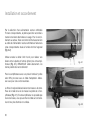
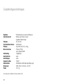
TD 700
Bedienungsanleitung
User Manual
Mode d Emploi
www.thorens.com
TD 700
Bedienungsanleitung
User Manual
Mode d Emploi
Inhalt
SICHERHEITSHINWEISE
6
AUSPACKEN UND MONTAGE
7
AUFSTELLUNG UND ANSCHLUSS
8
TONARM UND TONABNEHMERSYSTEM
10
AUFLAGEKRAFT
11
ANTISKATINGKRAFT
12
BETRIEB DES PLATTENSPIELERS
13
TECHNISCHE DATEN
14
SERVICEINFORMATIONEN
15
Table of Contents
Table des matiéres
SAFETY INSTRUCTIONS
17
INSTRUCTIONS DE SECURITE
28
UNPACKING AND SET UP
18
DEBALLAGE ET MONTAGE
29
PLACEMENT AND CONNECTIONS
19
INSTALLATION ET RACCORDEMENT
30
TONEARM AND PICKUP CARTRIDGE
21
BRAS ET TETE DE LECTURE
32
TRACKING FORCE
22
FORCE D‘APPUI
33
ANTI-SKATING FORCE
23
FORCE ANTISKATING
34
OPERATION OF RECORD PLAYER
24
UTILISATION DE LA PLATINE
35
TECHNICAL SPECIFICATIONS
25
CARACTERISTIQUES TECHNIQUES
36
CUSTOMER SERVICE
26
INFORMATIONS SERVICE APRES-VENTE
37
Sicherheitshinweise
BITTE VOR DER ERSTMALIGEN INBETRIEBNAHME
AUFMERKSAM LESEN!
VORSICHT
Um einen elektrischen Schlag zu vermeiden, darf das Gehäuse nicht geöffnet werden. Im Geräteinneren befinden sich keine vom Benutzer zu
wartenden Teile.
WARNUNG
UM DER GEFAHR VON FEUER UND EINES ELEKTRISCHEN SCHLAGES VORZUBEUGEN, DARF DAS GERÄT WEDER REGEN NOCH
FEUCHTIGKEIT AUSGESETZT WERDEN.
ERLÄUTERUNG DER GRAFISCHEN SYMBOLE
Das Blitz-Symbol mit dem nach unten weisenden
Pfeil im gleichseitigen Dreieck warnt vor “gefährlicher Spannung” im Gehäuseinneren, deren Höhe für
eine Gefährdung von Personen durch einen Stromschlag ausreichend ist.
Das Ausrufezeichen innerhalb des gleichseitigen
Dreiecks macht auf wichtige Bedienungs- und Wartungshinweise in der beiliegenden Bedienungsanleitung aufmerksam.
6
Dieses Elektronikprodukt entspricht den gültigen Richtlinien
zur Erlangung des CE-Zeichens. Alle notwendigen Prüfungen
wurden mit positivem Ergebnis vorgenommen.
WICHTIG: ENTSORGUNG VON ELEKTROGERÄTEN DURCH VERBRAUCHER IN PRIVATEN
HAUSHALTEN INNERHALB DER EU
Dieses Symbol auf dem Produkt oder dessen Verpackung gibt an, dass dieses Produkt nicht zusammen
mit dem Restmüll entsorgt werden darf. Es obliegt
daher Ihrer Verantwortung, das Gerät an einer entsprechenden Stelle für die Entsorgung oder Wiederverwertung von Elektrogeräten aller Art abzugeben
(z.B. ein Werkstoffhof). Die separate Sammlung und
das Recyceln Ihrer alten Elektrogeräte zum Zeitpunkt
ihrer Entsorgung trägt zum Schutz der Umwelt bei
und gewährleistet, dass sie auf eine Art und Weise
recycelt werden, die keine Gefährdung für die Gesundheit von Mensch und Umwelt darstellt. Weitere Informationen darüber, wo Sie alte Elektrogeräte
zum Recyceln abgeben können, erhalten Sie bei
den örtlichen Behörden, Werkstoffhöfen oder dort,
wo Sie das Gerät erworben haben.
Auspacken und Montage
Nehmen Sie das Gerät und die mitgelieferten Einzelteile
vorsichtig aus der Verpackung.
Lieferumfang:
1 x Bedienungsanleitung
1 x Chassis mit Innenteller und Tonarm
1 x Thorens Antriebsriemen
1 x Plattenteller mit Filzmatte
1 x Staubschutzhaube
1 x Tonarmgegengewicht
1 x Steckernetzteil
1 x Cinchkabel mit Erdungslitze
1 x Adapter für 17 cm Schallplatten
Abbildung 1
Legen Sie den Gummiantriebsriemen um den inneren
Plattenteller und die Riemenscheibe (Abb. 1). Platzieren
Sie danach den äußeren Plattenteller mit der Vertiefung
nach unten auf dem inneren Teller.
Vermeiden Sie Öl- oder Fettspuren auf Antriebsriemen,
Motor-Riemenscheibe und der Lauffläche des inneren
Plattentellers. Falls notwendig, können Sie diese Teile
mit einem in reinem Alkohol getränkten, nicht fasernden Tuch oder Lappen reinigen.
Setzen Sie anschließend die Staubschutzhaube in die
Scharniere auf der Rückseite des Chassis ein.
Der Plattenspieler ist nun vollständig montiert.
WICHTIG: Bitte bewahren Sie die Verpackung auf, falls
das Gerät einmal zum Transport verpackt werden muss.
Für Transportschäden durch unsachgemäße Verpackung
wird keine Haftung übernommen!
7
Aufstellung und Anschluss
Durch die Auswahl eines entsprechenden Thorens Netzteils kann der Plattenspieler an allen Netzspannungen betrieben werden. Zum Anschluss an das Stromnetz wird
der Niederspannungsstecker am Kabel des Steckernetzteils mit der entsprechenden Buchse rechts unten an der
Geräterückseite verbunden (Abb. 2.1).
Verwenden Sie anschließend das mitgelieferte Cinchkabel um eine Verbindung zwischen dem Plattenspieler und
dem (Phono-)Eingang Ihres Verstärkers herzustellen (Abb.
2.2). HINWEIS: Achten Sie hierbei unbedingt auf eine korrekte Verpolung der Anschlüsse!
Abbildung 2.1
Für Verstärker mit einer 5-poligen Eingangsbuchse nach
DIN benötigen Sie ein spezielles Adapterkabel. Bitte wenden Sie sich hierfür an Ihren Fachhändler.
Die getrennt geführte Litze stellt die Erd- bzw. Masseverbindung her. Verbinden Sie diese mit der Masseschraube
an Plattenspieler und Verstärker (Abb. 2.2). Besitzt Ihr Verstärker keine Masseschraube, so können Sie das Kabel
auch am Außenrand einer nicht verwendeten Eingangsbuchse anklemmen.
8
Abbildung 2.2
Ein Brummgeräusch in den Lautsprechern, dessen
Laustärke sich mit dem Lautstärkeregler beeinflussen
lässt, kann ein Zeichen für eine fehlerhafte Erdverbindung sein. Zunächst sollte untersucht werden, ob die
Masseverbindung einen sicheren Kontakt aufweist und
die Litze ggf. an einer anderen Stelle befestigt werden.
Sollte sich das Brummgeräusch hierdurch nicht beseitigen lassen, setzen Sie sich bitte mit Ihrem Fachhändler in Verbindung.
Achten Sie bei der Aufstellung Ihres neuen Plattenspielers
darauf, einen Mindestabstand zu anderen elektronischen
Geräten (z.B. Verstärker, Reciever oder CD-Spieler) einzuhalten, da es sonst zu magnetischen Einstrahlungen
auf das Tonabnehmersystem kommen kann, welche sich
durch Brummstörungen in der Wiedergabe äußern.
Thorens Plattenspieler sind relativ unempfindlich gegenüber Erschütterungen. Dennoch stellen diese ein generelles
Problem bei der Plattenwiedergabe mit hochwertigen Tonabnehmern dar. Wählen Sie deshalb ein möglichst stabiles
Möbelstück zur Aufstellung und vermeiden Sie die Nähe
zu Lautsprechern.
Leider reicht dies in älteren Häusern mit Holzbalkendecken bisweilen nicht aus. In der Regel hilft hier allerdings
die Aufstellung des Plattenspielers auf einer Konsole, die
mit geeigneten Konsolenträgern an einer tragenden Zimmerwand befestigt wird.
Magnetische Störungen kann man leicht ermitteln und
beseitigen, indem man Aufstellung und Position der
Geräte zueinander verändert.
9
Tonarm und Tonabnehmersystem
Ihr neuer Thorens TD 700 wurde mit vorinstalliertem Tonarm Thorens TP 42 und dem Tonabnehmersystem Audio
Technica AT-95E geliefert (Abb. 3).
Die vier farblich gekennzeichneten Anschlußlitzen werden
auf die entsprechenden Anschluß-Stifte (identische Farbe)
des Tonabnehmersystems geschoben.
HINWEIS: Die nachfolgenden Installationshinweise sind
nur von Bedeutung, falls Sie das Tonabnehmersystem
wechseln möchten.
Ältere Tonabnehmer weisen diese Farbkennung manchmal leider nicht auf. Verbinden Sie in diesem Fall nach folgendem Schema:
Am Tonarm TP 42 können nahezu alle auf dem Markt befindlichen Tonabnehmersysteme mit einem standardisierten Abstand der Befestigungslöcher von 12,5 mm (1/2 ”)
montiert werden.
R
G
L
G
Tonarm TP 42 mit Tonabnehmersystem AT-95E
Auflagekraft: 1,5 - 2,5 g / Empfohlene Auflagekraft: 2,0 g
10
rechter Kanal, rot (Signal)
rechter Kanal, grün (Masse)
linker Kanal, weiß (Signal)
linker Kanal, blau (Masse)
Abbildung 3
Auflagekraft
Das Gegengewicht wird von hinten auf das Tonarmrohr
geschoben und im Uhrzeigersinn aufgedreht (Abb. 4.1).
Abbildung 4.1
Der Tonarm wird anschließend bei abgesenkten Lift (siehe
Seite 12) zwischen Tonarmstütze und Plattenteller positioniert. Durch verdrehen des Gegengewichts kann der Tonarm nun ausbalanciert werden. HINWEIS: Entfernen Sie
hierzu unbedingt die Schutzhaube des Tonabnehmers!
Der Tonarm wird danach wieder in die Tonarmstütze eingerastet. Zur Einstellung der Auflagekraft wird nun das
Gegengewicht mit einer Hand am Verdrehen gehindert,
während mit der anderen Hand die vorne am Gewicht
befindliche Skalenscheibe so gedreht wird, dass die Nullmarke senkrecht über der Strichmarkierung des Tonarmrohres steht (Abb. 4.2).
Die Auflagekraft kann nun anhand dieser Skala (durch Verdrehen des Gegengewichts im Uhrzeigersinn) auf den vom
Hersteller des Tonabnehmersystems empfohlenen Wert
eingestellt werden, z.B. „20“ ( = 20 mN = 2,0 g – empfohlener Wert für den Tonabnehmer AT-95E).
Abbildung 4.2
11
Antiskatingkraft
Durch Zusammenwirken der Reibungskraft der Plattenrillen mit den Lagerkräften am Tonabnehmer wird beim Abspielen einer Schallplatte eine Kraftkomponente erzeugt,
die den Tonarm nach innen zieht: Die Skatingkraft.
Zu ihrer Kompensation dient die Antiskatingkraft, welche
beim Tonarm TP 42 durch einen eingebauten Magneten
erzeugt wird.
Die Einstellung der Antiskatingkraft erfolgt über einen
Drehregler (Abb.5). Folgende Werte können eingestellt
werden:
0
1
2
3
4
12
kein Antiskating
5 - 10 mN
10 - 15 mN
15 - 20 mN
> 20 mN
Abbildung 5
Betrieb des Plattenspielers
Der links vom Plattenteller angeordnete Schalter dient zur
Geschwindigkeitsauswahl. Es stehen zwei Geschwindigkeiten zur Verfügung, 33 U/min für Langspielplatten und
45 U/min für kleine Schallplatten. Rechts neben diesem
Schalter befindet sich die Start/Stop Taste (Abb. 6).
Zum Abspielen einer Platte wird der Plattenspieler zunächst
mit der entsprechenden Geschwindigkeit gestartet. Dann
wird der Tonarmlift (Abb. 7) angehoben, hierzu muss der
Hebel nach hinten bewegt werden. Nun wird der Tonabnehmer über der Einlaufrille oder über dem gewünschten
Stück positioniert und anschließend mithilfe des Lifts auf
die Platte abgesenkt (Hebel nach vorne bewegen).
Abbildung 6
Der Plattenspieler besitzt keine automatische Endabschaltung. Sobald die Auslaufrille erreicht ist, muss der Tonarm
mittels Handlift von der Platte gehoben und die Start/Stop
Taste betätigt werden.
Abbildung 7
13
Technische Daten
Antriebssystem
Antrieb
Geschwindigkeiten
Geschw.umschaltung
Plattenteller
Tonarm
Antiskating
Automatik
Endabschaltung
Kabelkapazität
Stromversorgung
Abmessungen
Gewicht
Riemenantrieb (innenliegend)
elektronisch geregelter
AC-Synchronmotor
33, 45 U/min
elektronisch
Acryl 300 mm (12”), 2,4 kg
Thorens TP 42
mit AT-95E Tonabnehmersystem
magnetisch
keine
keine
160 pF
landesspezifisches Steckernetzteil
465 x 350 x 145 mm (B x T x H)
10,1 kg
Technische Änderungen vorbehalten. Made in EEC.
14
Serviceinformationen
Ihr Fachhändler oder Vertrieb sind jederzeit kompetente
Ansprechpartner, die Ihnen bei sämtlichen Fragen rund
um Ihr Thorens Produkt gerne zur Verfügung stehen.
Sie können Thorens auch direkt kontaktieren:
Thorens Export Company AG
Im Huebel 1, CH-4304 Giebenach, Schweiz
www.thorens.com, [email protected]
HINWEIS: Bitte kontaktieren Sie im Garantiefall immer
zuerst Ihren Fachhändler oder Vertrieb!
Weitere Informationen unter:
www.thorens.com/de
15
Notizen
16
Safety instructions
PLEASE READ THIS PAGE CAREFULLY BEFORE
OPERATING YOUR UNIT!
CAUTION
To reduce risk of electric shock, do not remove the cover (or back).
No user-serviceable parts inside.
WARNING
TO PREVENT FIRE OR SHOCK HAZARD, DO NOT EXPOSE THIS
APPLIANCE TO RAIN OR MOISTURE.
EXPLANATION OF GRAPHICAL SYMBOLS
The lightning flash with arrowhead symbol, within
an equilateral triangle, is intended to alert you to
the presence of uninsulated ‘dangerous voltage’
within the product’s enclosure that may be of sufficient magnitude to constitute an electric shock to
persons.
The exclamation point within an equilateral triangle
is intended to alert you to the presence of important
operating and maintenance (servicing) instructions in
the literature accompanying the appliance.
This product was tested and complies with all the
requirements for the CE Mark.
IMPORTANT: DISPOSAL OF WASTE EQUIPMENT BY USERS IN PRIVATE HOUSEHOLDS
IN THE EUROPEAN UNION
This symbol on the product or on its packaging indicates that this product must not be disposed off
with your other household waste. Instead, it is your
responsibility to dispose of your waste equipment by
handing it over to a designated collection point for
the recycling of waste electrical and electronic equipment. The separate collection and recycling of your
waste equipment at the time of disposal will help to
conserve natural resources and ensure that it is recycled in a manner that protects human health and
the environment. For more information about where
you can drop off your waste equipment for recycling,
please contact your local city office, your household
waste disposal service or the shop where you purchased the product.
17
Unpacking and set-up
Carefully take the record player and its accessories out
of the carton and check if each of the following items has
been supplied:
1 x User manual
1 x Plinth with sub-platter and tonearm
1 x Thorens drive belt
1 x Platter with felt mat
1 x Dust cover
1 x Tonearm counterweight
1 x External mains adapter
1 x RCA interconnecting leads with
ground wire
1 x Adaptor for single records
Loop the drive belt around the sub-platter and motor
pulley (Fig. 1). Carefully put the main platter, depression
beneath, onto the sub-platter.
Please make sure that no oil or greasy substances can
get onto the belt and the transmission area of the subplatter. If necessary, both parts may be cleaned with an
alcoholic dilution added to a lint-free cloth.
18
Fig. 1
Attach dust cover to the hinges at the rear side of the
plinth – Your record player is now completely mounted.
IMPORTANT: It is highly recommended to save the shipping box and all packing material in case the record player
needs to be packed again for transportation. Thorens cannot be held responsible for any damage that may occur
during transport on the ground that the record player has
not been properly packed.
Placement and connections
By employing the appropriate (country-specific) Thorens
mains adapter this record player can be connected to
nearly any mains voltage supply. The low-tension plug of
the cord coming from the mains adaptor is to be inserted
into the respective socket at the rear side (right) of the
record player (Fig. 2.1).
Use the supplied RCA leads to connect the record player
to the phono input jack (RCA) of your amplifier or receiver
(Fig. 2.2). HINT: Make sure that the polarity is correct, i.e.
right/left channel output at the record player is to correspond with the right/left channel input.
Fig. 2.1
For amplifiers/receivers featuring a 5-pin DIN-socket at the
phono input section you will need a special adaptor (RCA
to DIN) which may be acquired from your Thorens dealer.
The separate thinner lead is used to make a connection
to ground. Connect this lead between the ground post
of the record player (Fig. 2.2) and the respective ground
post (GND) of your amplifier/receiver. If your amplifier does
not feature a separate ground post you may alternatively
attach the lead to the outer part of an unused RCA input
jack at the amplifier.
Fig. 2.2
19
The many possibilities of grounding an audio chain may
sometimes cause trouble in so far that a certain hum
can be heard through the speakers. This humming
noise becomes louder if the volume knob is turned
up. If there is audible hum we advise to re-check the
ground connection if it is securely fixed, or if perhaps
an alternative ground spot may remedy the problem.
In the event that causes for hum cannot be localised
and eventually eliminated please contact your Thorens
dealer for help.
When placing the record player onto its final position make
sure that it is a fair distance away from your other audio
devices, such as amplifier, receiver or CD player. This
measure is to avoid electro-magnetic interferences which
can yield a distorting effect in the sensitive pickup cartridge. This may be audible as hum during playback.
Electro-magnetic interferences however can be disclosed and eliminated by simply changing the position
of the record player with respect to the other devices.
20
Thorens record players are relatively insensitive when subject to foot-fall shocks or airborne resonance. Nevertheless, a general problem remains when it comes to playing
back vinyl records with a high-quality pickup cartridge. It
is therefore highly recommended to choose a sturdy piece
of furniture for placement and to avoid the proximity of the
record player to the loudspeakers.
Under certain circumstances all these precautions may not
be good enough in older houses with wooden floor construction. Here, in most cases a solid shelf firmly mounted
to a supporting wall can be very beneficial for the sonic
properties of the record player if it is placed on such a shelf
or console.
Tonearm and pickup cartridge
Your new Thorens TD 700 is supplied with pre-mounted
tonearm Thorens TP 42 and pickup cartridge Audio Technica AT-95E (Fig. 3).
The four colour-coded litz wires of the tonearm’s headshell
are attached to the respective pins (identical colours) at
the rear side of the cartridge.
HINT: the following mounting procedures are applicable
only in case you want to change to an other cartridge.
Some cartridges of yesterday however may not have colour-coded pins but show letters instead. We therefore advise to connect the litz wires as follows:
The tonearm TP 42 is made to accept nearly any pickup
cartridge with standardised 12.5 mm (1/2”) fixing holes.
Tonearm TP 42 with pickup cartridge AT-95E
Tracking force: 1.5 - 2.5 g / recommended: 2.0 g
R
G
L
G
right channel = red wire (signal)
right channel = green wire (ground)
left channel = white wire (signal)
left channel = blue wire (ground)
Fig. 3
21
Tracking force
The counterweight is attached to the rear end of the tonearm tube by carefully rotating it clockwise onto the tube
(Fig. 4.1).
Fig. 4.1
Lower the lift lever (see page 12) and move the tonearm
to a position in between the tonearm rest and the outer
rim or the platter. Now balance the tonearm by rotating
the counterweight either clockwise or counter-clockwise
until total equilibrium has been achieved. HINT: before doing so please remove the (detachable) stylus guard of the
cartridge.
Move the tonearm back to its rest and lock. In order to
adjust tracking force hold the main piece of the counterweight tight with the fingers of one hand to prevent it
from turning whilst the fingers of your other hand rotate
the tracking force dial until “0” on the dial is flush with the
white line on the rear tonearm tube (Fig. 4.2).
Tracking force can now be adjusted by slowly rotating the
counterweight clockwise (the dial is coupled to the weight)
until you have reached the tracking force recommended by
the manufacturer of the pickup cartridge, “20” for instance
( = 20 mN = 2.0 g – recommended for the AT-95E).
22
Fig. 4.2
Anti-skating force
The friction of the pickup stylus in the record groove and
the geometrical off-set position of the pickup in the headshell are generating a so-called skating force while playing
a record. This force tends to drag the tonearm towards the
centre of the record.
The TP 42 however features a built-in magnet for the compensation (anti-skating) of this unavoidable movement.
Anti-skating force is adjusted by a control knob at the base
of the tonearm (Fig. 5) whereby the settings correspond to
the applied tracking force (in mN), thus:
0
1
2
3
4
no effective anti-skating force
5 - 10 mN
10 - 15 mN
15 - 20 mN
> 20 mN
Fig. 5
23
Operation
The lever switch situated at the left side of the platter selects the platter speed. There are two speeds provided: 33
(rpm) for LPs and 45 (rpm) for singles. Next to this switch
on the right is the Start/Stop button (Fig. 6).
For playing back a record select the appropriate speed
and press the Start/Stop button. Then lift the tonearm up
by slowly pushing the lift lever up and back (Fig. 7). Move
the tonearm from its rest and position it above the leadin groove or above the desired piece/track to be played.
Slowly move the lift lever down whereupon the tonearm is
smoothly descending.
Fig. 6
This record player does not feature any automatic end-ofrecord shut-off facility. Therefore, as soon as the stylus has
reached the lead-out groove, the tonearm is to be lifted up
manually by the lever and the motor switched of by pressing the Start/Stop button.
Fig. 7
24
Technical specifications
Drive system
Motor
Speed
Speed change
Platter
Tonearm
Anti-skating
Automatic functions
Automatic shut-off
Capacity of leads
Voltage/Power supply
Dimensions
Weight
belt drive (beneath platter)
electronically controlled
AC synchronous motor
33 and 45 rpm
electronically
Acryl 300 mm (12”) 2.4 kg
Thorens TP 42
with pickup cartridge AT-95E
magnetic
n/a
n/a
160 pF
country-specified mains adapter
465 x 350 x 145 mm (W x D x H)
10,1 kg
Technical modifications subject to change without notice. Made in EEC.
25
Customer Service
Your Thorens dealer or distribution partner shall be
pleased to assist you in the event that you have any further
queries or need additional information concerning Thorens
products.
You may contact Thorens also directly:
Thorens Export Company Ltd.
Im Huebel 1, CH-4304 Giebenach, Switzerland
www.thorens.com, [email protected]
HINT: In case of warranty claims, you are kindly requested to contact your Thorens dealer or distribution partner
first
Further information may also be obtained from:
www.thorens.com
26
Notes
27
Instructions de sécurité
A LIRE ATTENTIVEMENT AVANT LA PREMIERE
MISE EN SERVICE!
ATTENTION
Le châssis ne doit pas être ouvert, afin d‘éviter tout choc électrique.
Aucune pièce nécessitant un entretien de la part de l‘utilisateur ne se
trouve à l‘intérieur de l‘appareil.
AVERTISSEMENT
POUR EVITER TOUT DANGER D‘INCENDIE ET DE CHOC ELECTRIQUE, L‘APPAREIL NE DOIT PAS ETRE EXPOSE A LA PLUIE ET A L‘HUMIDITE.
EXPLICATION DES SYMBOLES GRAPHIQUE
Le symbole éclair avec flèche vers le bas dans le
triangle avertit d‘une „tension dangereuse“ à l‘intérieur de l‘appareil, dont le niveau est suffisant pour
présenter un danger de choc électrique aux personnes.
Le point d‘exclamation à l‘intérieur du triangle indique des instructions de commande et d‘entretien
figurant dans le présent mode d‘emploi.
28
Ce produit électronique est conforme aux directives européennes pour l‘obtention de la marque CE. Tous les essais
nécessaires ont été effectués avec un résultat positif.
IMPORTANT:
ELIMINATION
D‘APPAREILS
ELECTRIQUES PAR LES UTILISATEURS PARTICULIERS RESIDANT DANS LA CE
Ce symbole, figurant sur le produit ou sur son emballage, indique que ce produit ne doit pas être éliminé avec les ordures ménagères. Il est de votre responsabilité de remettre ce produit à une entreprise
d‘élimination ou de recyclage d‘appareils électriques
de tous types (par ex. une décharge spécialisée)
La collecte sélective et la réutilisation de tous vos
anciens appareils électroniques à l‘occasion de leur
élimination, contribuent à la protection de l‘environnement et assure qu‘il soient recyclés de manière à
éviter de porter atteinte à la santé humaine et à la
protection de la nature. Pour obtenir de plus amples informations sur les dépôts et le recyclage des
appareils électroniques usagés, adressez-vous aux
autorités locales, aux déchèteries ou au distributeur
qui vous a vendu l‘appareil.
Déballage et montage
Sortez avec précaution l‘appareil et les pièces détachées
livrées de son emballage.
Contenu de 1 x mode d‘emploi
la livraison : 1 x châssis avec plateau intérieur
et bras de lecture
1 x courroie d‘entraînement Thorens
1 x plateau avec feutre
1 x capot de protection contre la poussière
1 x contrepoids de bras de lecture
1 x alimentation secteur enfichable
1 x câble Cinch avec tresse de mise à la terre
1 x adaptateur pour disques 17 cm
Fig. 1
Posez la courroie d‘entraînement en caoutchouc sur
le pourtour du plateau intérieur et de la poulie. (Fig. 1).
Positionnez ensuite le plateau extérieur sur le plateau
intérieur avec la partie creuse vers le bas.
Insérez ensuite le capot de protection contre la poussière
dans les charnières à l‘arrière du châssis.
Evitez toute trace d‘huile ou de graisse sur la courroie
d‘entraînement, sur la poulie moteur et sur la surface d‘entraînement du plateau intérieur. Si nécessaire,
vous pouvez nettoyer ces pièces à l‘aide d‘un chiffon
doux non pelucheux imprégné d‘alcool pur.
IMPORTANT: veuillez conserver l‘emballage, utile dans le
cas où l‘appareil devrait être remballé pour le transport.
Aucune garantie ne peut être accordée en cas d‘emballage non conforme!
La platine est maintenant entièrement montée.
29
Installation et raccordement
Par la sélection d‘une alimentation secteur enfichable
Thorens correspondante, la platine peut être raccordée à
toutes les tensions alternatives en usage. Pour le raccordement au secteur, il faut raccorder la fiche basse tension
au câble de l‘alimentation secteur enfichable à l‘aide de la
prise correspondante située à l‘arrière droit de l‘appareil
(Fig. 2.2).
Utilisez ensuite le câble Cinch fourni pour réaliser une
liaison entre la platine et l‘entrée (phono) de votre amplificateur (Fig. 2.1). REMARQUE: veillez absolument à la
bonne polarité des raccordements!
Fig. 2.1
Pour les amplificateurs avec une prise d‘entrée à 5 pôles
selon DIN, procurez-vous un câble d‘adaptation. Adressez-vous pour cela à votre revendeur.
Le fil de Litz séparé réalise la liaison de masse ou de terre.
Fixez-le à l‘aide de la vis de masse à la platine et à l‘amplificateur (Fig. 2.1). Si votre amplificateur ne possède pas
de vis de masse, vous pouvez fixer le câble au bord extérieur d‘une prise d‘entrée non utilisée.
30
Fig. 2.2
Un bourdonnement dans les haut-parleurs, dont le
niveau peut être influencé par le réglage du volume,
peut être le signe d‘une mauvaise liaison à la terre. Vérifiez d‘abord si la liaison de masse est assurée par un
bon contact et si le fil de Litz peut être fixé à un autre
endroit. Si le bourdonnement ne peut être éliminé par
ces essais, prenez contact avec votre revendeur spécialisé.
Lors du placement de votre nouvelle platine, veillez à respecter une distance minimale par rapport à d‘autres appareils électroniques (par ex. amplificateurs, récepteurs ou
lecteur de CD), car le système de lecture pourrait recevoir
des rayonnements électromagnétiques, qui pourraient se
traduire par des bourdonnements en cours de reproduction.
Les platines Thorens sont relativement insensibles aux vibrations. Cependant, celles-ci posent en général un problème pour la reproduction des disques avec des cellules
de lecture de qualité supérieure. Choisissez un meuble
stable comme support et évitez la proximité des hautparleurs.
Mais ceci n‘est pas suffisant dans le cas d‘anciennes demeures avec poutraison de plancher en bois. Dans ce
cas, il est utile de placer la platine sur une console qui est
elle-même vissée au mur porteur de la pièce à l‘aide de
ses propres supports de console.
De telles perturbations magnétiques peuvent être facilement identifiées et éliminées, en modifiant la position
de la platine par rapport aux autres appareils.
31
Bras et tête de lecture
Votre nouveau Thorens TD 700 vous a été livré avec un
bras de lecture Thorens TP 42 préinstallé et une cellule de
lecture Audio Technica AT 95E (Fig. 3).
Les quatre cosses de raccordement avec repères couleurs doivent être connectées aux picots correspondants
(même couleur) de la tête de lecture.
REMARQUE: les instructions d‘installation suivantes ne
sont importantes, que si vous voulez changer la cellule
de lecture.
Certaines têtes de lecture anciennes ne comportent malheureusement pas toujours ces codes couleurs. Dans ce
cas effectuer la connexion selon le schéma suivant:
Vous pouvez monter sur le bras de lecture TP 42 presque
toutes les têtes de lecture existantes sur le marché avec
écartement standard des trous de fixation de 12,5 mm
(1/2 pouce).
R
G
L
G
Bras de lecture TP 42 avec tête de lecture AT-95E
Force d‘appui: 1,5 - 2,5 g / force d‘appui recommandée: 2,0 g
32
canal droit, rouge (signal)
canal droit, vert (masse)
canal gauche, blanc (signal)
canal gauche, bleu (masse)
Fig. 3
Force d appui
Le contrepoids est monté sur le tube du bras de lecture
par l‘arrière et vissé dans le sens horaire (Fig. 4.1).
Fig. 4.1
Le bras est ensuite placé entre le support de bras et le plateau avec le lève-bras en position basse (voir page 12). Le
bras de lecture peut maintenant être équilibré par rotation
du contrepoids. REMARQUE: pour effectuer ce réglage,
il faut absolument retirer le capot de protection de la tête
de lecture!
Le bras de lecture est ensuite de nouveau encliqueté dans
le support de bras de lecture. Pour régler la force d‘appui,
empêchez la rotation du contrepoids d‘une main, en tournant le disque gradué se trouvant sur l‘avant du contrepoids sur le repère zéro à l‘aide de l‘autre main, de façon
à ce que la marque zéro se trouve au-dessus du trait du
bras de lecture (Fig. 4.2).
La force d‘appui peut maintenant être réglée (par rotation du contrepoids dans le sens horaire) à l‘aide de cette
échelle. Respectez les valeurs recommandées par le fabricant. Pour l‘utilisation de l‘AT-95E choissez «20» ( = 20 mN
= 2,0 g).
Fig. 4.2
33
Force antiskating
Pendant la lecture d‘un disque, la combinaison de la force
de frottement des sillons du disque avec les forces de la
tête de lecture génère une composante, qui tire le bras de
lecture vers le centre: la force skating.
Cette dernière est compensée par la force antiskating,
qui est produite par un aimant intégré au bras de lecture
TP 42
Le réglage de la force antiskating s‘effectue à l‘aide de
la rotation d‘une molette (Fig. 5). Les valeurs suivantes
peuvent être réglées:
0
1
2
3
4
34
pas d‘antiskating
5 - 10 mN
10 - 15 mN
15 - 20 mN
> 20 mN
Fig. 5
Utilisation de la platine
Le commutateur situé à gauche du plateau sert à la sélection de la vitesse de rotation. Deux vitesses de rotation sont possibles, 33 t/mn pour disque longue durée et
45 t/mn pour disques de petit diamètre. A la droite de ce
commutateur se trouve le bouton Start/Stop (marche/arrêt – Fig. 6).
Pour la lecture d‘un disque, démarrez d‘abord la platine
à la vitesse de rotation correspondante. Levez ensuite le
bras de lecture (Fig. 7), déplacez pour cela le levier vers
l‘arrière. Positionnez ensuite le bras de lecture au-dessus
du sillon de début du disque ou au début du sillon du
morceau souhaité, puis abaissez-le sur le disque à l‘aide
du levier (déplacez le levier vers l‘avant).
Fig. 6
La platine n‘est pas équipée d‘un arrêt automatique de fin
de disque. Dès que le sillon de fin de disque est atteint, le
bras de lecture doit être dégagé du disque manuellement
à l‘aide du levier et il faut actionner le bouton Start/Stop.
Fig. 7
35
Caractéristiques techniques
Système
d‘entraînement
Vitesses
Commutation vitesse
Plateau
Bras de lecture
Antiskating
Automatisme
Arrêt disque
Capacité câble
Alimentation
Dimension
Poids
Entraînement par courroie (intérieure)
Moteur synchrone CA avec
régulation électronique
33, 45 t/mn
électronique
Acryl 300 mm (12“), 2,4 kg
Thorens TP 42
avec cellule AT-95E
magnétique
sans
sans
160 pF
Alimentation enfichable spécifique pays
465 x 350 x 145 mm (L x P x H)
10,1 kg
Sous réserve de modification technique. Made in EEC.
36
Informations service après-vente
Votre distributeur spécialisé ou votre magasin sont des interlocuteurs compétents, qui sont à tout moment à votre
entière disposition pour toute question concernant votre
produit Thorens.
Vous pouvez également prendre directement contact
avec Thorens:
Thorens Export Company S.A.
Im Huebel 1, CH-4304 Giebenach, Suisse
www.thorens.com, [email protected]
REMARQUE: pour les questions de garantie, veillez toujours d‘abord contacter votre distributeur spécialisé ou
votre magasin!
Pour plus d‘information voir:
www.thorens.com
37
Notes
38
© 2006 Thorens Export Company AG
Im Huebel 1, CH-4304 Giebenach
E-Mail: [email protected]
Internet: www.thorens.com
analog high fidelity
Printed in Germany · UM700-0906-A