1
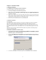
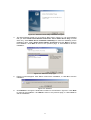
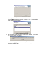
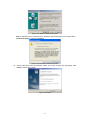
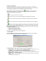
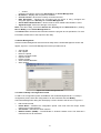
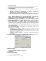
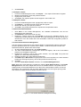
CMP-WNPCI10 Wireless LAN PCI 54 Mbps Manual ENGLISH Package Contents The following contents should be found in your box: One 54 Wireless Adapter One Resource CD including: • Wireless Client Utility (WCU) and Drivers • User Guide • Network cable Note: If any of the listed contents are damaged or missing, please contact the retailer from whom you purchased the Wireless Adapter for assistance. Chapter 1: Introduction 1.1 Overview of the product The Wireless Adapter gives you the flexibility to install your PC in the most convenient location available, without the cost of running network cables. The adapter's auto-sensing capability allows high packet transfer rate of up to 54Mbps for maximum throughput, or dynamic range shifting to lower speeds due to distance or operating limitations in an environment with a lot of electromagnetic interference. It can also interoperate with all 11Mbps wireless (802.11b) products. Your wireless communications are protected by up to 152-bit WEP and WPA encryption for high security. Transmission distance is 2-3 times further than of traditional 11g/b solutions, up to 855.36m. Transmission range is extended to 4-9 times. 1.2 Features Complies with IEEE802.11g, IEEE802.11b standards Transmission distance 2-3 times further than traditional solutions Supports WPA data security, IEEE802.1x authentication, TKIP/AES encryption, 64/128/152-bit WEP encryption Supports 108/54/48/36/24/18/12/9/6/11/5.5/3/2/1Mbps wireless LAN data transfer rates Provides 32-bit PCI interface (54M Wireless PCI Adapter) or 32-bit CardBus interface (54M Wireless CardBus Adapter) Supports Ad-Hoc and Infrastructure modes Supports roaming between access points when configured in Infrastructure mode Eases to configure and provides monitoring information Supports Windows 98, Me, 2000, XP 1 1.3 LED Status 1.3.1 54M Wireless PCI Adapter LED Indications LED Indications Status Status Green Intermittently Status Green Status Green Light up Flashing Working Status The adapter is in an electricity saving status or the adapter is already connected but is not transmitting or receiving data. The adapter is on wake up status. The adapter is transmitting and receiving data. 2 Chapter 2: Installation Guide 2.1 Hardware Installation 2.1.1 54M Wireless PCI Adapter Hardware Installation To install the adapter, follow these steps listed below: 1. Turn off your desktop PC and disconnect the power. 2. Open your PC case and locate an available PCI slot on the motherboard. Remove the metal slot cover on the back of the PC. Check with your computer manufacturer for instructions if needed. 3. Slide the PCI Adapter into the PCI slot. Make sure that all of its pins are touching the slot's contacts. Once the adapter is firmly in place, secure its fastening tab to your PC's chassis with a mounting screw. Then, close your PC case. 4. Reconnect your PC’s power and turn on your desktop PC. 2.2 Software Installation 2.2.1 Overview The Adapter’s Setup Wizard will guide you through the Installation procedure for Windows 2000, XP. The Setup Wizard will install the Wireless Client Utility (WCU) and drivers. When you install the hardware before installing the software, the system will prompt “Found New Hardware Wizard” window, click Cancel, and run the Setup Wizard program on the CDROM. The Setup steps for Windows 2000 and Windows XP are very similar. The following setup steps are for Windows 2000. 2.2.2 Software Installation for Windows 2000 1. Insert the Resource CD into your CD-ROM drive, click Start and choose Run. In the field that appears, enter F:\WNPCI10\Win2000_XP\Setup.exe (if “F” is the letter of your CDROM drive), figure 2-1 should then appear. 2. You can click Cancel to end the installation on the Preparing Setup screen, figure 2-1. Otherwise, the Setup Wizard will display a screen similar to that shown in figure 2-2 after a moment. Figure 2-1 Wireless Client Utility – Install Shield Wizard 3. To continue, click Next on the screen, figure 2-2. Click Cancel to end the Installation. 3 Figure 2-2 Wireless Client Utility Installation Program 4. The Setup Wizard will ask you to choose a Setup type in figure 2-3. It is recommended that you select Install Client Utilities and Driver. Select Install Driver Only to install driver only, select Make Driver Installation Diskette(s) to make the diskette(s) as the installation driver. Select Install Client Utilities and Driver and click Next to continue the Installation. Click Back to return to the previous page, or click Cancel to end the Installation. Figure 2-3 Select the setup type 5. Figure 2-4 should appear. Click Yes to continue the Installation, or click No to end the Installation. Figure 2-4 Question 6. Click Browse to change the destination location for the software in figure 2-5. Click Next to continue the Installation. Click Back to return to the previous page, or click Cancel to end the Installation. 4 Figure 2-5 Choose Destination Location 7. The Setup Wizard will ask you to create a new folder name or select one from the Existing Folders list shown in figure 2-6. It is recommended that you keep the default value. Click Next to continue the Installation. Click Back to return to the previous page, or click Cancel to end the Installation. Figure 2-6 Select a Program Folder 8. The Setup Wizard will notify you of how to proceed with the installation, shown in figure 2-7. Click OK to continue the Installation. Figure 2-7 Information prompt 9. While files are copying, you will see a warning box, shown in figure 2-8. Please select YES to continue installation. Our drivers have been tested thoroughly, and are able to work with the operating system. 5 Figure 2-8 Widows 2000 Warning Box Note: In Windows XP, the warning box is similar to that shown figure 2-8a. Please select Continue Anyway to continue installation. Figure 2-8a Windows XP Warning Box 10. After the files have been successfully copied, the screen in figure 2-9 will appear. Click Finish to reboot the system. Figure 2-9 Finish 6 Chapter 3: Configuration The Wireless Adapter can be configured by Wireless Client Utility (WCU). This chapter describes how to configure your Wireless Adapter for wireless connectivity on your Wireless Local Area Network (WLAN) and use the data security encryption features. After Installing the Adapter, the Adapter’s tray icon will appear in your system tray. It appears at the bottom of the screen, and shows the signal strength using color and the received signal strength indication (RSSI). If the icon is gray, there is no connection. If the icon is red, there is poor signal strength and the RSSI is less than 5dB. If the icon is yellow, there is poor signal strength and the RSSI is between 5dB and 10dB. If the icon is green, there is good signal strength and the RSSI is between 10dB and 20dB. If the icon is green, there is excellent signal strength and the RSSI is more than 20dB. Double-click the icon and the WCU utility will run. You can also run the utility by clicking the Start>Program>Wireless>Wireless Client Utility. The WCU utility provides a complete and easy to use set of tools to: Display current status information Edit and add configuration profiles Display current diagnostics information The section below introduces these above capabilities. 3.1 Current Status The Current Status tab contains general information about the program and its operations. The Current Status tab does not require any configurations. Figure 3-1 Current Status The following table describes the items found on the Current Status screen. Profile Name - The name of current selected configuration profile. Set up the configuration name on the General tab of Profile Management. Link Status - Shows whether the station is associated to the wireless network. Wireless Mode - Displays the wireless mode. Configure the wireless mode on the Advanced tab of Profile Management. Network Type - The type of network and the station currently connected. The options include: • Infrastructure (access point) 7 • Ad Hoc Configure the network type on the Advanced tab of Profile Management. IP Address - Displays the computer’s IP address. Current Channel - Shows the currently connected channel. Data Encryption - Displays the encryption type the driver is using. Configure the encryption type on the Security tab of Profile Management. Server Based Authentication - Shows whether server based authentication is used. Signal Strength - Shows the strength of the signal. Note: In the WCU utility, access the General tab, Security tab and Advanced tab by clicking New or Modify on the Profile Management tab. Click Advanced to see advanced information about the program and its operations. For more information, Please refer to the help file of the utility. 3.2 Profile Management Click the Profile Management tab of the WCU Utility and the Profile Management screen will appear, figure 3-2. The Profile Management screen provides tools to: Add a profile Edit a profile Remove a profile Switch to another Profile Import a Profile Export a Profile Scan Available Networks Order profiles Figure 3-2 Profile Management tab 3.2.1 Add or Modify a Configuration Profile To add a new configuration profile, click New on the Profile Management tab. To modify a configuration profile, select the configuration from the Profile list and click Modify. The Profile Management dialog box will display a screen similar to that shown in Figure 3-3. 1. Edit the General tab Profile Name - Identifies the configuration profile. This name must be unique. Profile names are not case-sensitive. Client Name - Identifies the client machine. Network Names (SSIDs) - The IEEE 802.11 wireless network name. This field has a maximum limit of 32 characters. 8 Figure 3-3 General Tab of Profile Management 2. Edit the Security tab Edit the fields in the Security tab of Profile Management to configure the profile. To define the security mode, select the radio button of the desired security mode. WPA - Wi-Fi Protected Access WPA Passphrase - Wi-Fi Protected Access Passphrase 802.1x - Enables 802.1x security. Shared Key (Static WEP) - Enables the use of shared keys that are defined on both the access point and the station. To define shared encryption keys, choose the Shared Key radio button and click Configure to fill in the Define Shared Keys window. None: No security (not recommended). Note: If the access point that the wireless adapter is associating to has WEP set to Optional and the client has WEP enabled, make sure that Allow Association to Mixed Cells is checked on the Security Tab to allow association. To complete WEP encryption configuration, you must select the 802.11 Authentication Mode as appropriate on the Advanced tab of this Profile Management dialog. Figure 3-4 Security tab of Profile Management Figure 3-5 Define Shared Keys 9 3. Edit the Advanced tab Transmit Power Level - Selects the transmit power level for 802.11b/g in mW. Actual transmit power may be limited by regulatory domain or hardware limitations. Power Save Mode • Maximum - Selects maximum mode to let the access point buffer incoming messages for the wireless adapter. The adapter will detect the access point if any messages are waiting periodically. • Normal - In Normal mode, the adapter will be switched to maximum mode automatically when no large packets are retrieved. • Off - turns power saving off, thus powering up the wireless adapter continuously for a short message response time. 802.11b Preamble - Specifies the preamble setting in 802.11b. The default setting is Short & Long (access point mode), which allows both short and long headers in the 802.11b frames. The adapter can only use short radio headers if the access point supports and uses them. Set to Long Only to override allowing short frames. Wireless Mode - Specifies 2.4 GHz 54 Mbps, 2.4 GHz 11 Mbps operation in an access point network. The wireless adapter must match the wireless mode of the access point with which it associates Wireless Mode when Starting an Ad Hoc Network - Specifies 2.4 GHz 54/11Mbps to start an Ad Hoc network if no matching network name is found after scanning all available modes. This mode also allows the selection of the channel the wireless adapter uses. The channels available depend on the regulatory domain. If the adapter finds no other ad hoc adapters, the channel that the adapter starts the ad hoc network with will be selected automatically. The wireless adapter must match the wireless mode and channel of the clients it associates. 802.11 Authentication Mode - Select which mode the wireless adapter uses to authenticate to an access point: • Automatic causes the adapter to attempt authentication using shared, but switches it to open authentication if shared fails. • Open System enables an adapter to attempt authentication regardless of its WEP settings. It will only associate with the access point if the WEP keys on both the adapter and the access point match. • Shared-key only allows the adapter to associate with access points that have the same WEP key. For infrastructure (access point) networks, click Preferred APs… to specify up to four access points to the client adapter that attempts to be associated to the access points. Figure 3-6 Advanced tab of Profile Management 3.2.2 Remove a profile 1. 2. 3. Go to the Profile Management tab. Select the profile name to remove in the Profiles List. Click Remove. 3.2.3 Switch another Profile 1. 2. Go to the Profile Management tab. Click on the profile name in the Profiles List. 10 3. Click Activate. 3.2.4 Import a Profile 1. 2. 3. 4. From the Profile Management tab, click Import…. The Import Profile will then appear. Browse to the directory where the profile is located. Highlight the profile name. Click Open, the imported profile will then appear in the Profiles List. 3.2.5 Export a Profile 1. 2. 3. 4. From the Profile Management tab, highlight the profile to export. Click Export…, the Export Profile window will then appear. Browse the directory to export the profile to. Click Save. The profile should then be exported to the specified location. 3.2.6 Scan Available Networks 1. 2. 3. Click Scan on the Profile Management, the Available Infrastructure and Ad Hoc Networks window will appear. Click Refresh to refresh the list at any time. Highlight a network name and click Activate to connect an available network. If no configuration profile exists for that network, the Profile Management window will open the General tab. Fill in the Profile name and click OK to create the configuration profile for that network. 3.2.7 Auto Profile Selection Management The auto selection feature allows the wireless adapter to automatically select a profile from the list of profiles and use it to connect to the network. To add a new profile into the Auto Selected Profiles list, please follow these steps. 1. On the Profile Management tab, click Order Profiles…. 2. The Auto Profiles Selection management window will appear, with a list of all created profiles in the Available Profiles box. 3. Highlight the profiles to add to auto profile selection, and click Add. The profile will appear in the Auto Selected Profiles box. 4. Highlight a profile in the Auto Selected Profiles box. 5. Click Move Up or Move Down as appropriate. Note: The first profile in the Auto Selected Profiles box has highest priority, and the last profile has lowest priority. 6. Click OK. 7. Check the Auto Select Profiles checkbox on the Profile Management tab. Note: When auto profile selection is enabled by checking Auto Select Profiles on the Profile Management tab, the client adapter will scan for an available network. The profile with the highest priority and the same SSID as one of the found networks will be used to connect to the network. If the connection fails, the client adapter will try the next highest priority profile that matches the SSID until an available network is found. Figure 3-7 Auto Profile Selection Management Dialog 11 DECLARATION OF CONFIRMITY We declare under our responsibility that the product; Brand name: KÖNIG Model: CMP-WNPCI10 Description: Wireless PCI adapter Is in conformity with the following standards; EN 300 328 V.1.4.1 (2003) EN 301 489-1 V.1.4.1 (2002) / EN 301 489-17 V.1.2.1 (2002) EN 60950-1: 2001 Following the provisions of the 1999/5/EC R&TTE Directive. Conform this regulation it’s allowed to use this product in all European Community & EFTA countries. Nedis BV is not responsible for the use of this product outside the European Community & EFTA countries. WARNING: Disconnect the product from mains and other equipment if a problem should occur. Do not expose the product to water of moisture. WARRANTY: No guarantee or liability can be accepted for any changes and modifications of the product or damage caused due to incorrect use of this product. GENERAL: Designs and specifications are subject to change without a notice. 12 www.konigcomputer.com 13