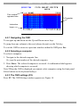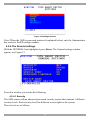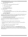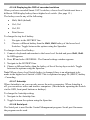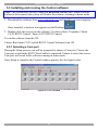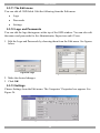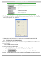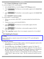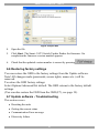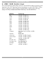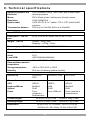
1
Smart CAT5 Switch 108 and 116 User Guide 1111 W. 35th Street, Chicago, IL 60609 USA www.tripplite.com/support Copyright ©2012 Tripp Lite. All rights reserved. SMART CAT5 SWITCH – 108/116 Table of Contents 1. Welcome ................................................................................................................................ 4 2. Introduction........................................................................................................................... 5 2.1 Features............................................................................................................................................. 5 2.2 System components ......................................................................................................................... 5 2.3 Compatibility ..................................................................................................................................... 6 2.4 The Smart CAT5 system configuration............................................................................................ 6 2.5 The Smart CAT5 models................................................................................................................... 7 2.6 Pre-installation guidelines................................................................................................................ 7 3. Connecting the Smart CAT5 system ................................................................................... 8 3.1 Connecting a ROC/RICC PS/2 .......................................................................................................... 8 3.2 Connecting a ROC/RICC USB .......................................................................................................... 9 3.3 Connecting a RICC SUN ................................................................................................................. 10 3.4 Connecting the CAT5 cables.......................................................................................................... 10 3.5 Connecting the KVM console ......................................................................................................... 10 3.6 Connecting the power supply ........................................................................................................ 10 3.6.1 Avoiding general rack mounting problems ................................................................................... 11 3.6.2 Rack mounting the Smart CAT5................................................................................................... 11 3.6.3 Rack mounting the RICCs ........................................................................................................... 12 3.6.4 Cascading Smart CAT5 switches................................................................................................. 12 4. Operating the Smart CAT5 system.....................................................................................14 4.1 The keyboard hotkeys .................................................................................................................... 14 4.2 Displaying the OSD......................................................................................................................... 14 4.2.1 Navigating the OSD ..................................................................................................................... 15 4.2.2 Selecting a computer ................................................................................................................... 15 4.2.3 The OSD settings (F2) ................................................................................................................. 15 4.2.4 The General settings ................................................................................................................... 16 4.2.4.1 Security .................................................................................................................................. 16 4.2.4.2 Administrator (Status A) ......................................................................................................... 17 4.2.4.3 Supervisor (Status S) ............................................................................................................. 17 4.2.4.4 User (Status U) ...................................................................................................................... 17 4.2.4.5 Activating password protection ............................................................................................... 17 4.2.4.6 Displaying the OSD of cascaded switches.............................................................................. 18 4.2.4.7 Autoskip ................................................................................................................................. 18 4.2.4.8 Serial port............................................................................................................................... 18 4.2.4.9 Changing the Keyboard language .......................................................................................... 19 4.2.4.10 Editing the Switch name ....................................................................................................... 19 4.2.5 F7 Defaults .................................................................................................................................. 19 4.2.6 The Ports settings........................................................................................................................ 19 4.2.6.1 Editing the computer name..................................................................................................... 20 4.2.6.2 Keyboard (KB)........................................................................................................................ 20 4.2.6.3 (HKEY) hotkey - Cascading.................................................................................................... 20 4.2.7 The Time settings ........................................................................................................................ 20 4.2.7.1 Scan (SCN) - Label (LBL) - Time out (T/O)............................................................................. 21 4.2.8 Users........................................................................................................................................... 21 1 USER GUIDE 4.2.9 Security ....................................................................................................................................... 22 4.2.10 The OSD HELP window – F1..................................................................................................... 23 4.2.11 Scanning computers– F4 ........................................................................................................... 24 4.2.12 Tuning – F5 ............................................................................................................................... 24 4.2.13 Moving the label – F6................................................................................................................. 24 4.2.14 Sending monitor emulation information to ROC/RICCs – F10 .................................................... 24 4.2.14.1 Updating the DDC information .............................................................................................. 25 5. Using the Control software .................................................................................................26 5.1 Control software system requirements ......................................................................................... 26 5.2 Connecting the RS232 Serial cable................................................................................................ 26 5.3 Installing and running the Control software.................................................................................. 27 5.3.1 Selecting a Com port ................................................................................................................... 27 5.3.2 Computer icons ........................................................................................................................... 28 5.3.3 Communication Error................................................................................................................... 28 5.3.4 The View menu............................................................................................................................ 28 5.3.5 Selecting a computer ................................................................................................................... 29 5.3.6 The toolbar buttons...................................................................................................................... 29 5.3.7 Get Status ................................................................................................................................... 29 5.3.8 Read Configuration...................................................................................................................... 29 5.3.9 Write Configuration ...................................................................................................................... 29 5.3.10 Renaming a computer................................................................................................................ 29 5.3.11 The Edit menu ........................................................................................................................... 30 5.3.12 Logo and Passwords ................................................................................................................. 30 5.3.13 Settings ..................................................................................................................................... 30 5.3.13.1 Single computer settings ...................................................................................................... 31 5.3.14 Loading a saved configuration ................................................................................................... 31 5.3.15 Reminder! .................................................................................................................................. 31 5.3.16 The factory default settings ........................................................................................................ 31 5.4 Password protection....................................................................................................................... 32 5.4.1 Administrator (Status A)............................................................................................................... 32 5.4.2 Supervisor (Status S)................................................................................................................... 32 5.4.3 User (Status U)............................................................................................................................ 32 6. Upgrading the Smart CAT5 firmware .................................................................................33 6.1 Obtaining the Update software and latest firmware...................................................................... 33 6.2 System requirements for the Smart CAT5 Update software......................................................... 33 6.3 Connecting the Smart CAT5 system.............................................................................................. 33 6.4 Installing the software .................................................................................................................... 34 6.4.1 Connecting the RS232 Serial cable ............................................................................................. 34 6.5 Starting and configuring the Smart CAT5 Update......................................................................... 34 6.5.1 Verifying the version numbers...................................................................................................... 35 6.5.1.1 OSD version number.............................................................................................................. 35 6.5.1.2 Smart CAT5 Manager version number ................................................................................... 36 6.5.1.3 ROC/RICC version number .................................................................................................... 36 6.5.2 Updating the firmware.................................................................................................................. 36 6.6 Restoring factory settings .............................................................................................................. 37 6.7 Update software - Troubleshooting ............................................................................................... 37 6.7.1 Resetting the units ....................................................................................................................... 38 2 SMART CAT5 SWITCH – 108/116 6.7.2 Getting the current status............................................................................................................. 38 6.7.3 Communication Error message.................................................................................................... 38 6.7.4 Electricity failure........................................................................................................................... 39 7. RICC SUN keyboard emulation...........................................................................................40 8. USB / SUN Combo keys ......................................................................................................41 9. Technical specifications .....................................................................................................42 9.1 Safety............................................................................................................................................... 43 9.2 WEEE compliance........................................................................................................................... 43 3 USER GUIDE 1 . We l c om e Thank you for buying the Smart CAT5 Switch system. This system is produced by Minicom Advanced Systems Limited. Technical precautions This equipment generates radio frequency energy and if not installed in accordance with the manufacturer’s instructions, may cause radio frequency interference. This equipment complies with Part 15, Subpart J of the FCC rules for a Class A computing device. This equipment also complies with the Class A limits for radio noise emission from digital apparatus set out in the Radio Interference Regulation of the Canadian Department of Communications. These above rules are designed to provide reasonable protection against such interference when operating the equipment in a commercial environment. If operation of this equipment in a residential area causes radio frequency interference, the user, and not Minicom Advanced Systems Limited, will be responsible. Changes or modifications made to this equipment not expressly approved by Minicom Advanced Systems Limited could void the user’s authority to operate the equipment. Minicom Advanced Systems Limited assumes no responsibility for any errors that appear in this document. Information in this document is subject to change without notice. No part of this document may be reproduced or transmitted in any form or by any means, electronic or mechanical, for any purpose, without the express written permission of Minicom Advanced Systems Limited. Trademarks PS/2 is a registered trademark of International Business Machines Corporation. All other trademarks and registered trademarks are the property of their respective owners. 4 SMART CAT5 SWITCH – 108/116 2 . I nt r od u c t i on Access and control multiple multi-platform computers from one Keyboard Video Mouse (KVM) console with the Smart CAT5 Switch (Smart CAT5) system. The Smart CAT5 comes in 108 and 116 models. Connect up to 8 computers to the 108 model, and up to 16 to the 116 model. The Smart CAT5 is based on Minicom’s innovative ROC technology in which each computer/ server is directly connected to the switch via RIC on Cable (ROC) using standard CAT5 cable at a distance of up to 30m/99ft in a star configuration. The system also works with Minicom’s RICCs using standard CAT5 cable up to 10m/33ft. The system can contain a mixture of ROCS and RICCs. No external power is needed at the remote ROC/RICCs. 2.1 Features Hot-Swap - disconnect and reconnect computers without rebooting Scan-mode operation with variable time interval 1U Rack mountable Operate the system using an On Screen Display (OSD) or Control software or front panel push buttons or keyboard hotkeys Create multi-level cascade arrangements. For example by cascading the Smart CAT5 116, connect up to up to 256 computers in the system The computers can be placed up to 10m/33ft from the Smart CAT5 Multi-platform — supports PS/2, SUN, and USB computers/servers 2.2 System components The Smart CAT5 system consists of: Smart CAT5 Switch 108 or 116 Remote Interface Connection cables (RICCs) – PS/2, SUN, USB RICC on Cable (ROCs) - PS/2, USB CAT5 cables (1.5m provided) RS232 Serial cable Rack mounts for the Smart CAT5 and the ROC/RICCs 5 USER GUIDE 2.3 Compatibility The Smart CAT5 is compatible with: PS/2, SUN and USB computers/servers VGA, SVGA, or XGA monitors DOS, Windows, LINUX, UNIX, MAC and all other major operating systems 2.4 The Smart CAT5 system configuration Figure 1 illustrates the basic configuration of the Smart CAT5 system. Workstation SMART CAT5 SWITCH 116 www.minicom.com 11 12 13 14 15 16 1 2 3 4 5 6 7 8 h p w o r k s ta ti on b 2 6 0 0 To servers IC OM 100-240 VAC 50/60 Hz 10 MIN POWER COMPUTER 9 h p w o r k s ta ti on b 2 6 0 0 RoC/RICCs h p w o r k s ta ti on b 2 6 0 0 h p w o r k s ta ti on b 2 6 0 0 h p w o r k s ta ti on b 2 6 0 0 h p w o r k s ta ti on b 2 6 0 0 h p w o r k s ta ti on b 2 6 0 0 Figure 1 Smart CAT5 system configuration 6 SMART CAT5 SWITCH – 108/116 2.5 The Smart CAT5 models Figure 2 illustrates the front panel of the Smart CAT5 116 model. The 108 model is the same but with only 8 columns of LEDs. MINICOM SELECT SMART CAT5 SWITCH Selected CPU on 1 2 3 4 5 6 7 8 9 10 11 12 13 14 15 16 Figure 2 Smart CAT5 116 front panel The figure below illustrates the rear panel of the Smart CAT5 116 unit. The 108 model is the same but with only 8 Computer ports. www.minicom.com COMPUTER POWER 100-240 VAC 50/60 Hz 9 10 11 12 13 14 15 16 1 2 3 4 5 6 7 8 Figure 3 Smart CAT5 116 rear panel 2.6 Pre-installation guidelines Switch off all computers Place cables away from fluorescent lights, air conditioners, and machines that are likely to generate electrical noise Ensure that the maximum distance between each computer and the Smart CAT5, does not exceed 10m/33ft 7 USER GUIDE 3 . C o n ne c t i n g t he S m a r t C AT 5 s ys t e m Each computer/ server is directly connected to the Smart CAT5 via the appropriate ROC or RICC using CAT5 cable in a star configuration. The system can contain a mixture of RoCs and RICCs. No external power is needed at the remote ROC/RICCs. The ROC/RICCs draw their power from the computer’s keyboard port (ROC/RICC PS/2, SUN) or from the USB port (ROC/RICC USB). The figures below illustrate the ROC PS/2 and ROC USB. To computer’s Video card To computer’s keyboard port To computer’s mouse port Figure 4 ROC PS/2 To computer’s Video Card To computer’s USB Port Figure 5 ROC USB (SUN) 3.1 Connecting a ROC/RICC PS/2 The connections for ROC/RICC PS/2 are exactly the same. Figure 6 illustrates the RICC PS/2. You can connect the ROC/RICC PS/2 to a powered on computer, but it must be in the following order: 1. Connect the Mouse connector to the computer’s Mouse port. 2. Connect the Keyboard connector to the computer’s Keyboard port. 3. Connect the Screen connector to the computer’s Video port. Failure to connect in the above order while the server is running, may lead to the mouse malfunctioning until the server is rebooted. 8 SMART CAT5 SWITCH – 108/116 NetServer tc2100 To Keyboard port Mouse Keybd 100T To Mouse port Parallel Serial A RICC PS/2 Video Serial B To Video port SCSI CAT5 cable to Smart CAT5 Computer port PCI 33Mx32b PCI 33Mx32b PCI 33Mx32b PCI 33Mx32b Figure 6 RICC PS/2 connections 3.2 Connecting a ROC/RICC USB The ROC/RICC USB supports Windows 98 SE and later, MAC, SUN, SGI and all modern Linux distributions. The connections for ROC/RICC USB are exactly the same. Figure 7 illustrates the RICC USB and its connections. To connect the ROC/RICC USB: 1. Connect the Screen connector to the computer’s Video port. 2. Connect the USB connector to the computer’s USB port. To Video port RICC USB CAT5 cable to Smart CAT5 Computer port Figure 7 RICC USB 9 To USB Port USER GUIDE 3.3 Connecting a RICC SUN Figure 8 illustrates the RICC SUN and its connections. To connect the RICC SUN: 1. Connect the Screen connector to the computer’s Video port. 2. Connect the Keyboard connector to the computer’s Keyboard port. To Video port To Keyboard Port RICC SUN CAT5 cable to Smart CAT5 Computer port Figure 8 RICC SUN 3.4 Connecting the CAT5 cables 1. Connect one connector to the ROC/RICCs RJ45 port. 2. Connect the other connector to one of the Smart CAT5’s Computer ports. 3. Follow the above 2 steps for each computer. 3.5 Connecting the KVM console To connect a KVM console to the Smart CAT5: 1. Connect the monitor’s connector to the Smart CAT5’s Monitor port. 2. Connect the keyboard’s connector to the Smart CAT5’s Keyboard port. 3. Connect the mouse’s connector to the Smart CAT5’s Mouse port. 3.6 Connecting the power supply 1. Connect the Smart CAT5 to the power supply using the Power cable provided. Use only power cord supplied with the unit. 2. Switch on the computers. 10 SMART CAT5 SWITCH – 108/116 3.6.1 Avoiding general rack mounting problems Elevated operating ambient temperature The operating ambient temperature of the rack environment may be greater than the room ambient when installing into a closed or multi-unit rack assembly. So install the equipment in an environment compatible with the maximum rated ambient temperature. Reduced airflow Install the equipment in a rack in such a way that the amount of airflow required for safe operation is not compromised. Mechanical loading Mount the equipment in the rack in such a way that a hazardous condition is not achieved due to uneven mechanical loading. Circuit overloading When connecting the equipment to the supply circuit, consider the effect that overloading of circuits might have on over-current protection and supply wiring. Reliable earthing of rack-mounted equipment should be maintained. Give attention to supply connections other than direct connections to the branch circuit (e.g. use of power strips). 3.6.2 Rack mounting the Smart CAT5 The Smart CAT5 comes with screw holes on the side for easy rack mounting, see figure below. Screw holes for bracket Figure 9 Screw holes for rack mounting Use the L-shaped brackets and screws provided to mount the Smart CAT5 on a server rack as illustrated below. The length of the screws used for connecting the brackets to the Smart CAT5 unit must not exceed 5 mm. 11 USER GUIDE Screw the bracket into the side of the unit Screw to the rack here Figure 10 Connecting the L-shaped bracket 3.6.3 Rack mounting the RICCs You can attach the RICCs to a server rack or computer using the Velcro strips provided. Or connect it using the bracket provided. The figure below illustrates the bracket. Insert screws through bracket and into the rack Insert screw through bracket and into the back of a computer Insert screws through bracket and into the back of the RICC Insert screws through bracket and into the back of the RICC Figure 11 Rack mounting the RICC 3.6.4 Cascading Smart CAT5 switches You can cascade the Smart CAT5 system. You do so by connecting the lower level Smart CAT5 Switches to ROC/RICCs. Follow the connections as illustrated in the figure below. 12 SMART CAT5 SWITCH – 108/116 With the Smart CAT5 116 model, connect up to up to 256 computers through cascading. A lower level Switch must have a different hotkey to display its OSD than a higher level switch. Changing the OSD display hotkey is explained on page 18 below. P110 SD KVM Console Top level Smart CAT5 Switch ww w.minicom.c om COMPUTER 9 10 11 12 13 14 15 16 1 2 3 4 5 6 7 8 POWER 100-250 VAC 50/60 Hz Set Switch Hotkey to Ctrl-Ctrl MINICOM To RoC/RICCs Second level Smart CAT5 Switch 8 MINICOM MINICOM MINICOM Parallel 7 Serial A 6 100T 5 Mouse 4 K eybd 3 Parallel 2 Serial A 1 POWER 100-250 VAC 50/60 Hz Video Video Video S erial B S erial B S erial B Switch Hotkey Shift-Shift (default) 100T 16 Mouse 15 K eybd 14 Parallel 13 Serial A 12 100T 11 Mouse 10 K eybd www.minicom.com COMPUTER 9 To RoC/ RICCs MINICOM Mous e Keybd Mous e Keybd Mous e Keybd Second level 100T 100T 100T MINIC OM MINICOM Parallel Serial A Parallel Serial A Parallel Serial A Smart CAT5 Switch V ideo V ideo Serial B Serial B Serial B COMPUTER 9 10 11 12 13 14 15 16 1 2 3 4 5 6 7 8 POWER 100-250 VAC 50/60 Hz www.m inicom.com V ideo Switch Hotkey Shift-Shift (default) To RoC/ RICCs Figure 12 Cascading Smart CAT5 switches 13 USER GUIDE 4 . O pe r a t i n g t he S m a r t C AT 5 s ys t e m Switch between the connected computers by either The front panel Select buttons Keyboard hotkeys The OSD (On Screen Display) or Control software The OSD is also the place to adjust various settings as explained below. When switching computers the illuminated LED of the top bank indicates which computer is currently selected. 4.1 The keyboard hotkeys To switch to the next computer forwards press Shift then, +. Release Shift, before pressing +. To switch to the next computer backwards press Shift then, -. Release Shift, before pressing -. Note! With a US English keyboard you can use the + key of the alphanumeric section or of the numeric keypad. With a Non-US English keyboard only use the + key of the numeric keypad. 4.2 Displaying the OSD To display the OSD: Press Shift twice. The OSD Main window appears. See Figure 13. Lines with yellow text show active computers. Lines with blue text show inactive computers. The Type column indicates whether a computer “C” or another switch “S” is connected to the port. 14 SMART CAT5 SWITCH – 108/116 Port number appears here C=Computer Instruction keys Figure 13 OSD Main window 4.2.1 Navigating the OSD To navigate up and down use the Up and Down arrow keys. To jump from one column to the next (when relevant) use the Tab key. To exit the OSD or return to a previous window within the OSD press Esc. 4.2.2 Selecting a computer To select a computer: 1. Navigate to the desired computer line. Or, type the port number of the desired computer. 2. Press Enter. The selected computer is accessed. A confirmation label appears showing which computer is accessed. Note! When the OSD is displayed you cannot select computers using the front panel Select buttons or the keyboard hotkeys. 4.2.3 The OSD settings (F2) Press F2. The OSD Settings window appears see Figure 14. 15 USER GUIDE Figure 14 Settings window Note! When the OSD is password protected (explained below) only the Administrator has access to the F2 settings window. 4.2.4 The General settings With the GENERAL line highlighted, press Enter. The General settings window appears see Figure 15. Figure 15 General Settings window From this window you can do the following: 4.2.4.1 Security The OSD comes with an advanced password security system that contains 3 different security levels. Each security level has different access rights to the system. These levels are as follows: 16 SMART CAT5 SWITCH – 108/116 4.2.4.2 Administrator (Status A) The Administrator can: Set and modify all Passwords and security profiles Fully access any computer Use all OSD functions 4.2.4.3 Supervisor (Status S) The Supervisor can: Fully access any computer Access the following OSD functions only –F4 Scan, F5 Tune and F6 Moving the Confirmation label. 4.2.4.4 User (Status U) There are 6 different Users in the Smart CAT5 system. Each User has a Profile set by the Administrator that defines the access level to different computers. There are 3 different access levels; these are explained on page 21. 4.2.4.5 Activating password protection By default OSD access is not password protected. Only the Administrator can password-protect the OSD or disable password protection. To do so: 1. In the General settings window navigate to the Security line. 2. Press the Spacebar to toggle between Security On and Off. The password box appears. 3. Type the Administrator’s password (default is “admin”). 4. Press Enter. The new security status is set. If you forget the Administrator's password, go to www.minicom.com. From the Support menu select Smart Switches. There you will find information that explains how to restore a lost password or reset the switch to its default settings including the default password. 17 USER GUIDE 4.2.4.6 Displaying the OSD of cascaded switches When you have cascaded Smart CAT5 switches, a lower level Switch must have a different OSD display hotkey than a higher level switch. (See page 12.) The hotkeys can be any of the following: Shift, Shift (default) Ctrl, Ctrl Ctrl, F11 Print Screen To change the top level hotkey: 1. Navigate to the HOTKEY line. 2. Choose a different hotkey than the Shift, Shift hotkey of the lower level Switches. Toggle between the options using the Spacebar. To change a lower level hotkey: 1. Connect a keyboard and monitor to the lower level Switch and press Shift, Shift. Its OSD appears. 2. Press F2 and select GENERAL. The General settings window appears. 3. Navigate to the HOTKEY line. 4. Choose a different hotkey than the hotkey of the of the top layer switch. Toggle between the options using the Spacebar. Note! When a lower level Switch hotkey is changed, there is an adjustment to be made in the higher level Switch’s OSD: This is explained on page 20-(HKEY) hotkey - Cascading. 4.2.4.7 Autoskip When Autoskip is on, you can only access the active computers. When Autoskip is off, you can access active and inactive computers. (This includes operating the Switch via the OSD, front panel buttons or hotkeys). To change the Autoskip setting: 1. Navigate to the Autoskip line. 2. Toggle between the options using the Spacebar. 4.2.4.8 Serial port The Serial port is used for the Control Management program. Serial port On means the program can be used. 18 SMART CAT5 SWITCH – 108/116 To change the Serial port setting: 1. Navigate to the Serial port line. 2. Toggle between the options using the Spacebar. 4.2.4.9 Changing the Keyboard language In the OSD the names of the computers can be written in 3 different languages – English (EN), German (DE), and French (FR). The keyboard is preset to English; this can be changed as follows: 1. Navigate to the Keyboard language line. 2. Toggle between the options using the Spacebar. 4.2.4.10 Editing the Switch name You can substitute up to 18 characters in the line. A space constitutes a character. When there is more than one switch in the system give each Switch’s OSD a different name. 4.2.5 F7 Defaults Press F7 to return the OSD to the factory default settings. Note! All changes made will be removed. 4.2.6 The Ports settings From the General Settings, return to the Settings window by pressing Esc. Navigate to the Ports line and press Enter. The Ports settings window appears see Figure 16. Figure 16 Ports Settings window 19 USER GUIDE 4.2.6.1 Editing the computer name In this window you can edit the computer names with up to 15 characters. When you have a cascaded CAT5 KVM Switch connected to a Computer port give the switch a distinct name. See Figure 16. To erase a character: Select it and press the Spacebar. Blank spaces remain in place of the erased character. To erase an entire line: Place the cursor at the beginning of the line. Keep the Spacebar depressed until the line is erased. 4.2.6.2 Keyboard (KB) By default the Keyboard mode is set to PS, which is suitable for Windows, Linux, MAC OS, SUN Solaris and most other operating systems. For certain UNIX operating systems set the KB column as follows: U1 for HP UX U2 for Alpha UNIX, SGI, Open VMS U3 for IBM AIX 4.2.6.3 (HKEY) hotkey - Cascading When there are cascaded switches, and the lower level Switch has had its OSD display hotkey changed, you must do the following: Adjust the HKEY setting in the Ports Settings window of the higher level switch to reflect the lower level switch’s new hotkey. To reflect the new hotkey: 1. On the line to which the Switch is connected, press Tab to jump to the HKEY column. 2. Toggle between the options using the Spacebar. 3. Return to the Settings window by pressing Esc. 4.2.7 The Time settings In the Settings window navigate to the Time line and press Enter. The Time settings window appears see Figure 17. 20 SMART CAT5 SWITCH – 108/116 Figure 17 Time settings window 4.2.7.1 Scan (SCN) - Label (LBL) - Time out (T/O) SCN - In the SCN column, change the scan period. LBL - In the LBL column, change the display period of the OSD label showing which computer is currently accessed. T/O - When password protection is activated you can automatically disable the Management keyboard, mouse and screen after a preset time of non-use. Set this Timeout period in the T/O column. To set the above periods: 1. On the desired line press Tab to jump to the desired column. 2. Place the cursor over one of the 3 digits and type a new number. Enter a leading zero where necessary. For example, type 040 for 40 seconds. Typing 999 in the LBL column displays the label continuously. Typing 000 – the label will not appear. Typing 999 in the T/O column disables the Timeout function. Warning! Typing 000 causes the Timeout function to work immediately. Minimum time should be not less than 005 seconds. Typing 999 in the SCN column displays the screen for 999 seconds. Typing 000 – the computer screen is skipped. 4.2.8 Users In the Settings window navigate to the Users line and press Enter. (Note! Users is only enabled if the security status is set to On, see page 17). The Users settings window appears see Figure 18. 21 USER GUIDE Figure 18 Users settings window There are 3 different access levels. These are: Y – Full access to a particular computer. Plus access to the F4, F5 and F6 OSD functions V –Viewing access only, to a particular computer (No keyboard/mouse functionality) N – No access to a particular computer – A TIMEOUT label appears if access is attempted To give each user the desired access level: 1. Navigate to the desired computer line and User. 2. Toggle between the options using the Spacebar. 4.2.9 Security In the Settings window navigate to the Security line and press Enter. The Security settings window appears see Figure 19. 22 SMART CAT5 SWITCH – 108/116 Figure 19 Security settings window The ‘T’ column on the right hand side stands for Type of password. There can only be 1 Administrator password, 1 Supervisor password, and 6 User passwords. To change a user name or password: 1. Navigate to the desired line and column. 2. Type a new user name / password. User authentication is done solely via the password there is no security significance to the names. By default the User Profile settings are full access. 4.2.10 The OSD HELP window – F1 To access the HELP window press F1. The HELP window appears see Figure 20. Figure 20 HELP window Please note! All the functions set out in the Help window are performed from the Main window. The Help window is merely a reminder of the hotkeys and their functions. 23 USER GUIDE 4.2.11 Scanning computers– F4 Where necessary adjust the scan time in the Time Settings window, see above. To activate scanning: 1. Press Shift twice to open the OSD. 2. Press F4. Your screen displays each active computer sequentially, with the Scan label appearing in the top left corner. To deactivate scanning: Press F4. 4.2.12 Tuning – F5 You can tune the image of any remote computer screen from the Select Computer window. To adjust the screen image: 1. Navigate to the remote computer you wish to adjust. 2. Press F5. The screen image of the selected computer appears, together with the Image Tuning label. 3. Adjust the image by using the Right and Left Arrow keys. 4. When the image is satisfactory, press Esc. Note! Picture quality is relative to distance. The further away a remote computer is from the Smart CAT5, the lower the image quality, and the more tuning needed. So place the higher resolution computers closer to the manager unit. 4.2.13 Moving the label – F6 Position the OSD label anywhere on the screen. To position the label from the Main window: 1. Navigate to the desired computer using the Up and Down arrow keys. 2. Press F6. The selected screen image and Identification label appears. 3. Use the arrow keys to move the label to the desired position. 4. Press Esc to save and exit. 4.2.14 Sending monitor emulation information to ROC/RICCs – F10 Display Data Channel (DDC) is a VESA standard for communication between a monitor and a video adapter. 24 SMART CAT5 SWITCH – 108/116 Input the DDC information of the monitor connected to the Smart CAT5 switch into the memories of all connected ROC/RICCs when first installing system. To input the DDC information: 1. Disconnect the Video cable of all ROC/RICCs from the computers. 2. Press Shift twice to open the OSD. 3. Press F10. “Please wait” flashes a few times and disappears. The monitor’s DDC information is sent to all ROC/RICCs. 4. Reconnect the Video cable of all ROC/RICCs. 4.2.14.1 Updating the DDC information Update the DDC information in any of the following circumstances: When replacing the monitor connected to Smart CAT5 Switch When adding a new ROC/RICC to the system When reconnecting an existing ROC/RICC that was temporarily used in a different system To update the DDC information, repeat the steps as set out above. 25 USER GUIDE 5 . U s i n g t he Co n t r ol s of tw a r e As an alternative to the OSD, you can operate the system with the Control software located on our website www.minicom.com in the Support section on the Smart CAT5 Switch Upgrades page. With the OSD you operate the system and view the computer screens on the same monitor. The Control software requires 2 monitors: 1 for the software and 1 to view the computer screens. With the Control software you can: View computers Edit OSD settings Save configurations for future use Read configurations from and write configurations to the Smart CAT5 Switch 5.1 Control software system requirements Pentium 166 or higher computer 16Mb RAM Windows 98 and later Free Serial port 5.2 Connecting the RS232 Serial cable To run the software, connect the RS232 Serial cable to the computer containing the software, and to the Smart CAT5. See the figure below. SMART CAT5 SWITCH 116 www.minicom.com POWER 100-240 VAC 50/60 Hz COMPUTER 9 10 11 12 13 14 15 16 1 2 3 4 5 6 7 8 To Service connector RS232 Download cable MIN ICO M Control software installed here MIN ICO M RoC/RICCs to servers Figure 21 Connecting the RS232 Serial cable 26 SMART CAT5 SWITCH – 108/116 5.3 Installing and running the Control software Note! The system must be fully connected BEFORE running the Control software. Failure to first connect the system will lead to the software working in demo mode. 1. Download the software from www.minicom.com and install it on your computer. Once installed, a shortcut icon appears on the Desktop . 2. Double-click the icon to run the software. Or choose Start / Programs / Smart CAT5 RS232 Control / Smart CAT5 RS232 Control. To run the software from the CD: Choose Run Smart CAT5 switch RS232 Control Software from CD. 5.3.1 Selecting a Com port During the Setup process you will be prompted to choose a Com port. Choose the Com port to which the RS232 Serial cable is connected. Failure to select the correct Com port will result in the software running in demo mode. Once Setup is complete the Control window appears. See the figure below. Figure 22 Control window 27 USER GUIDE 5.3.2 Computer icons Icon Meaning Computer is connected and switched on Computer is switched off or unconnected Computer that you are presently connected to Connected and switched on computer with a Local Workstation attached and presently being used locally. After remaining idle for the Timeout period, it changes to yellow. When you first open the Control window the software automatically gets the status of the system, including the security access settings. 5.3.3 Communication Error If a Communication Error box appears when trying to scan the system – Figure 23. Figure 23 Communication Error Check that: The RS232 Serial cable is connected to the computer’s Serial port and the Smart CAT5 service port. The Com Port settings in Options / Com Port are set correctly. After changing the Com port exit and re-enter the Control software. 5.3.4 The View menu From the View menu choose to display: All computers, or only active switched on computers. The Legend The toolbar 28 SMART CAT5 SWITCH – 108/116 5.3.5 Selecting a computer To select a computer: Click on the computers icon. The system switches to that computer. The connected icon appears with a red background . Control and monitor the selected computer from the keyboard and mouse connected to the Smart Switch. 5.3.6 The toolbar buttons The toolbar buttons are explained below. 5.3.7 Get Status If for whatever reason there is a break in communication between the Control software and the system, click to get the current status of the computers in system. The system automatically updates the status before every switching. 5.3.8 Read Configuration To see the current settings of the entire system (names, scan settings etc.) click . All current settings are received. You view the computer settings from the Control window and other settings from the Edit menu – discussed below. 5.3.9 Write Configuration With the Control software you can make changes to all OSD settings. You can then save these configurations in a file to use in the future by selecting Save or Save As from the File menu. Note! Save or Save As will have no affect on the OSD. To change the OSD settings you must press or choose Write Configuration from the File menu after making changes. The changes will then be sent to the Smart system Manager, and the OSD will reflect these changes. 5.3.10 Renaming a computer To rename a computer: 1. Type the new name in the box below the computer icon. 2. Click to send the new name to the system. Or click Save or Save As from the File menu to save the change in a file and not alter the OSD names. 29 USER GUIDE 5.3.11 The Edit menu You can edit all OSD fields. Edit the following from the Edit menu. Logo Passwords Settings 5.3.12 Logo and Passwords You can edit the logo that appears at the top of the OSD window. You can also edit the names and passwords for the Administrator, Supervisor and 6 Users. 1. Edit the Logo and Passwords by choosing them from the Edit menu. See figures below. Figure 24 Logo Figure 25 Names and passwords 2. Make the desired changes. 3. Click OK. 5.3.13 Settings Choose Settings from the Edit menu. The Computers’ Properties box appears. See Figure 26. Figure 26 Computers’ Properties box 30 SMART CAT5 SWITCH – 108/116 Here you can edit all the data that can be edited in the OSD. This includes: Scan times, Timeout, Confirmation label display time, Keyboard type/mode, User access, Password mode, Autoskip mode, and Switch/System hotkey. These features are explained in the OSD section of this Appendix. To edit a setting: 1. In the Computer List, select the desired computer or group of computers. 2. Make the desired changes. 3. Check the Select box next to the changed setting. 4. Click OK. 5.3.13.1 Single computer settings To see all the settings of a single computer, right click the computer icon. The settings appear as in the figure below. Note! There is no Select box to check. Figure 27 Single computer Settings box 5.3.14 Loading a saved configuration To load a saved configuration: From the File menu choose Open. 5.3.15 Reminder! All changes done with the Control software are only reflected in the OSD AFTER pressing . 5.3.16 The factory default settings To revert to the factory default settings: On the toolbar press . There is no need to press 31 . USER GUIDE 5.4 Password protection When the Smart CAT5 system is password protected, the Control software behaves in exactly the same way as the OSD. You must type in the required password to access the Control software. The access you gain depends on the security status – exactly as with the OSD. To change the security access, close and reopen the Control software, and type in the different password. 5.4.1 Administrator (Status A) The Administrator can: Set and modify all Passwords and security profiles Fully access any computer Use all functions 5.4.2 Supervisor (Status S) The Supervisor can: Fully access any computer Scan computers. 5.4.3 User (Status U) There are 6 different Users in the Smart CAT5 system. Each User has a Profile that defines the access level to different computers. There are 3 different access levels. These are: Y – Full access to a particular computer V –Viewing access only, to a particular computer (No keyboard/mouse functionality) N – No access to a particular computer The Administrator defines the desired access levels of each User Profile. This is done in the Setting box. By default the User Profile settings are full access. 32 SMART CAT5 SWITCH – 108/116 6 . U p gr a di n g t he S m a r t C AT 5 f i r mw a r e With the Smart CAT5 Update software program you can upgrade the firmware for the: OSD Manager ROC/RICCs Smart CAT5 Update enables you to add new features and fix bugs in a quick and efficient manner. You can also return the OSD to the factory default settings via the Update software. Install the Smart CAT5 Switch Update on any computer, even one not part of the Smart CAT5 system. 6.1 Obtaining the Update software and latest firmware The Update software and latest firmware for your system are located on our website at: http://www.minicom.com/phandlc.htm The firmware can be downloaded in different ways: Complete Firmware Package – This includes the firmware for all Smart switches and RICCS and ROCS. Firmware Package for Smart Switch models - This includes the firmware for all Smart switches. Smart CAT5 Switch Firmware - There are multiple hardware versions of Smart CAT5 Switch units, each with version specific firmware. On the web page find the description and table that identifies your version. Firmware Package for RICC and ROC models – Download a firmware package for RICC and ROC models (see the table on the web page for the Supported RICC/ROC models). Or search for and download the specific RICC/ROC models with the correct firmware version. 6.2 System requirements for the Smart CAT5 Update software Pentium 166 or higher with 16 MB RAM and 10 MB free Hard Drive space. Free Serial port. Windows 2000 and later. 6.3 Connecting the Smart CAT5 system To update the firmware, the Smart CAT5 system must be connected and switched on. 33 USER GUIDE 6.4 Installing the software Download the Update software and install it on your computer. 6.4.1 Connecting the RS232 Serial cable To run the software, connect the RS232 Serial cable to the computer containing the Update software, and to the Smart CAT5 Switch. See page 26. 6.5 Starting and configuring the Smart CAT5 Update 1. Start the Smart CAT5 Update software by double-clicking the icon on your desktop , or choose Start/Programs/Smart CAT5 Switch Update/Smart CAT5 Switch Update. The Smart CAT5 Update window appears. See Figure 28. Smart Switch RICCs/RoCs Status box Figure 28 Smart CAT5 Switch Update window The table below explains the functions of the buttons and boxes in the Smart CAT5 Switch Update window. Button or Box Function Selects all RICCs Unselects selected RICCs Starts firmware download Displays the firmware version number Displays the hardware version number 34 SMART CAT5 SWITCH – 108/116 Button or Box Function Cancels selected function System time Displays device status Name of Update file 2. To change the Com Port from the Options menu choose Com Port. The Com Port Dialog box appears. See Figure 29. Figure 29 Com Option box 3. Choose the Com Port the RS232 Serial cable is connected to and click OK. 6.5.1 Verifying the version numbers Before upgrading the firmware, you must first verify which firmware and hardware versions you have. 6.5.1.1 OSD version number To verify the OSD version number: 1. In the Switch Unit box, check the OSD option. See Figure 28. 2. Click . The version number appears in the Switch box. The H/W Version button is grayed out, as there is no hardware relevant to the OSD. 35 USER GUIDE 6.5.1.2 Smart CAT5 Manager version number To verify the Smart CAT5 version number: 1. In the Switch Unit box, check the Smart CAT5 Manager option. 2. Click box. . The firmware version number appears in the Switch Unit 3. Click box. . The hardware version number appears in the Switch Unit 6.5.1.3 ROC/RICC version number To verify the RICC version number: 1. Before you can check a ROC/RICC, you must uncheck the Switch Unit box options. 2. Check one or more or all of the ROC/RICCs. 3. Click . The firmware version number appears after the ROC/RICC number. 4. Click . The hardware version number appears after the ROC/RICC number. When “Not responding” appears, there is no computer connected, or it is switched off. 6.5.2 Updating the firmware Warning! Never switch off any computer connected to the Smart CAT5 system during the updating process. To update the firmware: 1. In the Smart CAT5 Switch Update window, check the appropriate option in the Switch Unit box or the desired RICC/ROC. 2. From the File menu, choose Open. The Open box appears. See Figure 30. 3. Navigate to the folder that contains the firmware update file. You may only see the files that match the file selection mask. When the firmware is contained in a Firmware Package, select the package. The package comes with a .min extension. The correct firmware is automatically selected according the Switch or RICC/ROCC chosen in step 1 above. The file extension for specific devices is .hex. 36 SMART CAT5 SWITCH – 108/116 Figure 30 Open box 4. Open the file. 5. Click Start. The Smart CAT5 Switch Update flashes the firmware. On completion the firmware version number appears. 6. Check that the updated version number is correct by pressing . 6.6 Restoring factory settings You can restore the OSD to the factory settings from the Update software. Note! All changes made (passwords, access rights, names etc.) will be removed. To restore the OSD factory settings: Select Options/Advanced/Set default. The OSD returns to the factory default settings. (You can also restore the OSD from the OSD (F7), see page 19). 6.7 Update software - Troubleshooting This section covers: Resetting the units Getting the current status Communication Error message Electricity failure 37 USER GUIDE 6.7.1 Resetting the units Resetting can be done from the Update software or from the Smart CAT5 switch. Resetting through the Update software Reset the software for the Smart CAT5 Manager or ROC/RICCs when for example the unit hangs or when the mouse fails to work properly. Resetting is done via the Serial port, and avoids the need to shut down the computer. NOTE! The Reset function does not affect the parameters of the unit settings. To reset the Switch or RICC units: 1. For the Switch, check the Smart CAT5 Switch option. For the ROC/RICCs, check one or more ROC/RICCs. 2. From the Options menu choose Advanced / Reset. The units reset. The system should now be operational. Resetting from the Smart CAT5 switch To reset from the Switch press the 2 front panel Select buttons simultaneously. The ROC/RICCs are unaffected by this reset. 6.7.2 Getting the current status If there is a break in communication between the Update software and the system, select Options/Get Number of Ports to get the current status of the system. 6.7.3 Communication Error message When using Firmware Update software you may sometimes get a Communication Error message. When updating a unit and a Communication Error message appears, do the following: 1. Check that the RS232 Serial cable’s RS232 connector is connected to the Switch’s Communication port. 2. Check that the RS232 Serial cable’s DB9F connector is connected to the DB9M Serial port on the CPU’s rear panel. 3. Restart the download process. 38 SMART CAT5 SWITCH – 108/116 6.7.4 Electricity failure When the electricity fails while updating the Smart CAT5 firmware, do the following: If the electricity fails during the firmware update of the Switch, a Communication Error message appears. Simply resume the firmware update by opening the folder that contains the firmware update file and continue from there. If the electricity fails during the firmware update of the ROC/RICCs a Not Responding or Upgrade Error message appears. Restart the upgrade from the beginning. 39 USER GUIDE 7 . R I C C S U N k e yb o a r d e m ul a t i on By default the RICC SUN supports US English keyboard emulation. It also supports German and Swiss German keyboard emulation. You can download the appropriate keyboard emulation firmware from our website www.minicom.com in the Support section on the Smart CAT5 Switch Upgrades page. Upload the firmware to the RICC SUN. Other language keyboard emulations will be posted on the Minicom Web site as they become available. 40 SMART CAT5 SWITCH – 108/116 8 . U S B / S UN C om b o k e ys The connected PS/2 keyboard does not have a special SUN keypad to perform special functions in the SUN Operating System environment. So when a ROC/RICC USB or SUN is connected to a SUN computer, the ROC/RICC emulates these SUN keys using a set of key combinations called Combo keys. See the table below. SUN key Combo key Stop Left Ctrl + Left Alt + F1 Props Left Ctrl + Left Alt + F3 Front Left Ctrl + Left Alt + F5 Open Left Ctrl + Left Alt +F7 Find Left Ctrl + Left Alt + F9 Again Left Ctrl + Left Alt + F2 Undo Left Ctrl + Left Alt + F4 Copy Left Ctrl + Left Alt + F6 Paste Left Ctrl + Left Alt + F8 Cut Left Ctrl + Left Alt + F10 Help Left Ctrl + Left Alt + F11 Compose Application key or Left Ctrl + Left Alt + Keypad * Crescent Scroll Lock Volume Up Left Ctrl + Left Alt + Keypad – Volume Down Left Ctrl + Left Alt + Keypad + Mute Left Ctrl + Left Alt + F12 Sun Left ◊ key Left Windows key Sun Right ◊ key Right Windows key Alt-Graph Right Alt or Alt Gr Stop A Left Ctrl + Left Alt +1 41 USER GUIDE 9 . Te c hni c a l s p e c i f i c a t i o ns Operating systems and Platforms DOS, Windows, LINUX, UNIX, MAC and all other major operating systems Mouse PS/2, Wheel mouse, Intellimouse, 5-button mouse Resolution 1600x1200@75Hz System cable CAT5/ 5E/ 5+/ 6/ or 7 cables. FTP or UTP 2x4x24 AWG solid wire Transmission distance RICCs up to 10m/33ft. RoCs up to 30m/99ft. Smart CAT5 Switch Dimensions – 108/116 port 215.0 x 122.0 x 41.5mm / 8.46 x 4.80 x 1.63in Weight – 108/116 Product – 920g / 2lbs Shipping – 1.87Kg / 4.1lbs Power supply – 108/116 Internal switching 85-260 VAC 50 / 60 Hz Connections System Serial Local KVM RJ45 RJ11 HDD15/MinDin6/MiniDin6 Operating / Recommended ambient temperature 0ºC to 40ºC/32ºF to 104ºF Storage temperature -40ºC to 70ºC/-40ºF to 158ºF Humidity 80% non-condensing relative humidity ROC/RICCs ROC/RICC PS/2 ROC/RICC USB RICC/SUN VGA Keyboard/Mouse System HDD15 MiniDin6 RJ45 HDD15 USB RJ45 HDD15 MiniDin8 RJ45 Power From computer’s Keyboard port From USB port From computer’s Keyboard port Connections Product weight All RICCs 107g / 0.23lb. - All RoCs 100g / 0.20lb Shipping weight All RICCs 300g / 0.66lb - All RoCs 172g / 0.38lb Dimensions All RICCs 91 x 41 x 24mm / 3.58 x 1.61 x 0.94” All RoCs 65 x 25 x 25mm / 2.55 x 0.98 x 0.98” 42 SMART CAT5 SWITCH – 108/116 9.1 Safety The device must only be opened by an authorized Minicom technician. Disconnect device from AC mains before service operation! 9.2 WEEE compliance WEEE Information for Minicom Customers and Recyclers Under the Waste Electrical and Electronic Equipment (WEEE) Directive and implementing regulations, when customers buy new electrical and electronic equipment from Minicom they are entitled to: Send old equipment for recycling on a one-for-one, like-for-like basis (this varies depending on the country) Send the new equipment back for recycling when this ultimately becomes waste Instructions to both customers and recyclers/treatment facilities wishing to obtain disassembly information are provided in our website www.minicom.com. 43 USER GUIDE 201204196 • 933193 44