1
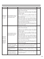
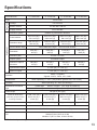
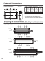
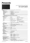
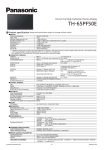
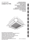
Operating Instructions
Touch Panel
Model No.
TY-TP42P30K
TY-TP50P30K
TY-TP60P30K
TY-TP65P30K
Before connecting, operating or adjusting this product, please read these instructions completely.
Please keep this manual for future reference.
English
Contents
Ŷ Precautions with regard to setting up ........................2
Ŷ Maintenance .............................................................3
Ŷ Components .............................................................4
Ŷ Touch Panel Assembly ..............................................5
Ŷ Mounting Touch Panel ...............................................6
Ŷ Connection with Computer ........................................8
Ŷ Operating Conditions.................................................8
Ŷ Touch Operation ........................................................9
Ŷ Before Calling for Service........................................10
Ŷ Speci¿cations ..........................................................13
Ŷ External Dimensions ...............................................14
Ŷ Drawing of Screw Holes ..........................................14
Precautions with regard to setting up
WARNING
Only a quali¿ed technician should perform installation.
• Incorrect installation may cause an accidental fall of the equipment resulting in personal injury.
Do not disassemble or modify the equipment.
• Doing so may cause a ¿re or electric shock.
Stop using the equipment if anything abnormal occurs.
• Using the equipment even when it is generating smoke or an odor or in other abnormal conditions may cause a ¿re or other
accidents.
• Stop using it immediately and contact your dealer for repair. Do not repair it by yourself because doing so can be dangerous.
Do not place nearby a container with water or such other liquid in it.
• If water or other liquid is spilled on or gets inside the equipment, a ¿re or electric shock may occur. (E.g., Àower vases, Àower
pots, glass, and bottles containing cosmetic liquid, chemical liquid or water)
Prevent the equipment from getting wet.
• Doing so may cause a ¿re or electric shock.
Do not allow foreign materials to get in the equipment.
• Do not insert or let metal objects or combustible materials in the equipment because that may cause a ¿re or electric shock.
“Pay special attention to children’s behavior.”
CAUTION
Do not use the equipment with any other device than the main device speci¿ed in the catalog.
• Otherwise the unit may be dropped and become damaged, and personal injury may result.
Installation should be performed only in the speci¿ed procedure.
• Incorrect installation may cause an accidental fall of the equipment resulting in personal injury.
Do not place the equipment in a humid or dusty location or in a location where the equipment may be exposed to oil
smoke or steam.
• Doing so may cause a ¿re or electric shock.
Use only the special components for installation.
• Otherwise the main device may fall and get damaged resulting in personal injury.
Two or more people are required to install or remove the main device.
• Otherwise the main device may fall causing personal injury.
Tighten all the screws securely when assembling the equipment.
• Improper assembly may cause an accidental fall or damage of the equipment resulting in personal injury.
Unplug the connecting cable before moving the equipment.
• Failure to do so may cause an accidental fall or turnover resulting in personal injury.
Note for an installation technician
Ŷ Please hand over these operating instructions to the customer after installation.
Ŷ Panasonic shall not be accountable for any accident or damage caused by incorrect installation or mishandling.
2
Maintenance
Setup location
Places where the touch panel should not be setup include:
• Locations exposed to direct sunlight, and locations near powerful light sources
(The equipment is an optical touch panel utilizing infrared rays and may function incorrectly when adversely affected.)
• Dusty or humid locations
• Locations that may be exposed to impact or vibration
• Locations near emissions of chemicals or steam, or locations where contact may be made with chemicals
• Locations near sources of electrical noise (generators, air conditioners etc.)
Cautions when in use
Do not touch the infrared transmissive area and screen until the OS starts up after
the computer is turned on.
• Such an action will be detected as defective elements resulting in malfunction of the
equipment. Should this occur, restart the computer. Also when disconnecting and
connecting the USB cable, do not touch the infrared transmissive area and screen.
Infrared
transmissive
area
When using other devices utilizing infrared rays, keep them away from the
equipment to prevent erroneous operation.
Use only the touch pen included with this equipment. Operation is not guaranteed
with other products.
When using the touch panel, be careful not to apply an excessive load to it by
pressing the touch panel body or in any other way.
Cautions when moving
Keep the equipment away from any impact when moving. Failure to do so may result in failure.
Hold the main device when moving.
• Gripping this equipment to move may result in failure.
Do not hold the USB cable when moving.
• Doing so may damage the USB cable resulting in a failure.
Maintenance
* Be sure to unplug the USB cable before cleaning the equipment.
Use a soft cloth and lightly wipe off dirt on the surface of the equipment.
• If soiling is severe, wet a cloth in neutral detergent diluted by 100 times with water, wring well, wipe off the soiled part, and
then wipe well with a dry cloth.
• If liquid droplets get inside, the equipment as well as the screen of the main device may fail. Also do not rub up the screen
with strong force.
Use a soft cloth and wipe off dirt on the surface of the infrared transmissive area.
• Once a day, use a soft cloth to wipe off any soiling or debris on the infrared transmissive area. Failure to do so will cause a
malfunction, but on such an occurrence you can restore normal function simply by gently wiping the soiling off.
• If soiling is severe, wet a cloth in neutral detergent diluted by 100 times of water, wring well, wipe off the soiled part, and then
wipe well with a dry cloth.
Do not directly spray or apply detergent.
• If liquid droplets get inside, the equipment may fail.
Do not apply volatile materials such as insecticides, benzene or thinner.
• The panel may get deteriorated or the coating may come off.
Do not keep the equipment contacted with rubber or plastic materials for a long time.
• The cabinet may get deteriorated.
• When using a chemical wipe, follow the instructions supplied with it.
Cleaning of the inside should be performed at least once a year. Consult your dealer for cleaning.
• If dust builds up inside, the level of infrared light available for touch detection will decrease and may result in poor operation.
Consult your dealer for cleaning of the inside at least once a year.
3
Components
(Check the components and their quantities.)
Touch panel
(1) Mounting bracket A
(for top side)
Mounting bracket A
(for bottom side)
Mounting bracket B
(4)
Mounting screw A
(8)
Mounting screw B
(8)
(2)
(2)
Accessories
USB extension cable
(1) CD-ROM
• Operating Instructions
• Driver software
Touch pen
(2)
(1) Operating Instructions
Ŷ Illustrations are conceptual views and may differ in shape from the actual equipment.
Ŷ The specifications of the product are subject to change without notice.
• Windows is a registered trademark of Microsoft Corporation in the USA and other countries.
(The official name of Windows is Microsoft® Windows® Operating System.)
• The names of other companies and products appearing in this publication are the trademarks,
registered trademarks or products names of their respective owners.
4
(1)
Touch Panel Assembly
Note
• Place the touch panel making its front surface face down on a clean cloth or blanket to prevent the front
surface of the touch panel from getting scratched or dirty during work.
Mounting in horizontal posture
Attach the mounting brackets A (for top and bottom sides) to the touch panel with the mounting screws A (2 each).
See the ¿gure below for the screw holes of attachment positions.
The procedure for vertical posture is the same.
Mounting screw A
Mounting
bracket A
(for top side)
Mounting
bracket A
(for bottom
side)
Mounting screw A
Attachment positions
(8 holes without screws in them)
Mounting in vertical posture
Check in the ¿gure below the positions where the brackets are attached, and remove the screws (8 in total from top and bottom sides).
Attach the mounting brackets A (for top and bottom sides) with the mounting screws A (2 each) to the screw
holes from which the screws were removed.
Notes
• For screw holes of other models than 42V, see “Drawing of Screw Holes” (page 14).
• Keep the screws which were removed.
Top side (42V)
1
2
3 4
2
3 4
5
6
Bottom side (42V)
1
5
5
Mounting Touch Panel
Notes
• Two or more people are always required for mounting.
• Never mount the main device in the way that is overlapped from above the touch panel while the touch
panel is laid down.
Doing so may damage the touch panel.
1 Fit the assembled touch panel from the front side of the main device.
Note
• There should not be a space between the touch panel and the
front surface of main device.
The procedure for vertical posture is the same.
Mount in the way that the USB port becomes lower left when
seen from the front.
2 Prepare the mounting brackets B.
Mounting bracket B
Temporarily fix the mounting screws B. (2 or 3 turns)
3 As shown in the figure below, attach the mounting brackets B to the mounting brackets A (for top side) on
the left and right of the top side.
Temporarily fix the screws.
Attach on the left and right of the bottom side in the same way.
Attaching to the top side
Mounting bracket B
Securely insert the projection of the
mounting bracket B to the cutout.
Attaching to the bottom side
Mounting bracket B
Securely insert the projection of the
mounting bracket B to the cutout.
6
4 Referring to the alignment mark shown in the figure below, adjust the position seeing from the front so that
the touch panel does not lean to one side.
End of the screen
Touch panel
alignment mark
Power lamp window
5 After adjusting the position, completely tighten the screws which
were temporarily fixed.
• Note that tightening the screws too tight may deform the bracket.
Notes
• There should not be a space between the touch panel and the front
surface of the main device.
• Con¿rm that lighting of the power lamp can be seen from the power
lamp window. If it cannot be seen due to misalignment, move the
touch panel horizontally to make ¿ne adjustment.
7
Connection with Computer
USB connector type A
(Female)
Touch panel
USB connector type A
(Male)
Connect to the
USB port on
your computer.
Computer
Main device
USB connector type A
(Male)
To connect to your computer,
see the instruction manual of
the main device.
Caution
• If the infrared transmissive part on the screen is shaded by your ¿ngers or other things when connecting the
USB extension cable, that may be detected as a failure during initialization and, if no corrective action is taken,
touch detection may not correctly function partially.
In that case, disconnect and reconnect the USB extension cable. At this time, restarting the computer is not
necessary.
• Because some cables may not ensure the proper functioning of the equipment, use the USB extension cable
supplied with the equipment.
Operating Conditions
OS of computer
IBM PC/AT compatible machine with USB ports,
supporting the OS below
Windows XP (SP2 or later, 32 bit or 64 bit)
Windows Vista (32 bit or 64 bit)
Windows 7 (SP1 or later, 32 bit or 64 bit)
Caution
• The USB ports should function correctly.
• If a previous version of driver has been installed, disconnect the USB cable of the touch panel from the
computer, uninstall the previous version, and then install the new one.
• For installation and uninstallation of the touch panel driver, see the installation manual of the touch panel driver
software included in the supplied CD-ROM.
• When using Windows 7, installation of the touch panel driver is not necessary.
When using Windows XP or Vista, follow the descriptions of the installation manual of the driver software
included in the supplied CD-ROM for connection of the USB extension cable and setup of the touch panel
driver software.
8
Touch Operation
Use the supplied touch pen.
The touch operations are different depending on the OS used.
Dual touch is not possible on Windows XP and Vista.
Windows
XP/
Vista
Single tap
Applicable
Function
7
Applicable
Functions as a left click of mouse.
Functions as a double-click by quickly touching twice. The
Double tap
Applicable
Applicable
pen or a finger should be set apart enough from the panel
window before the second touch is made. If the distance is not
enough, the double tap may not be correctly recognized.
Drag and drop
Flick
Press and hold
Pan
Applicable
Not
applicable
Not
applicable
Not
applicable
Applicable
Functions as a drag and drop of mouse by touching, moving a
¿nger while it is kept contacted and then releasing it.
When a frequently executed operation has been set, Àipping
Applicable
a finger toward the location of the function to be used can
execute the operation.
Functions as a right click by touching and holding on the area
Applicable
of the screen where you want to make a right click and then
releasing it.
On a page with the scroll bar, touching and moving toward
Applicable
the direction you want can scroll the page along with the
movement.
On the screen which can be zoomed in and out, touching the
Zoom
Not
applicable
screen with two fingers and separating the touching points
Applicable
from each other in the manner of stretching enables zooming
in. Moving the touching points closer in the manner of pinching
enables zooming out.
Press and tap
Not
applicable
Functions as a right click of mouse by touching and holding
Applicable
a ¿nger on the screen and quickly making a single tap with
another ¿nger.
Caution
• When using Windows 7, con¿rm that “Enable multi-touch gestures and inking” is checked in “Pen and Touch” of
the Control Panel.
• When operating between two points, touch operation may not function correctly if the touch operation is too
fast, if the distance between the two points is too short, or if the two points are crossing.
• Touch operation may not correctly function if any obstacle is between the sensor and the operating ¿nger.
• For more information about touch operation, see the help information of Windows.
9
Before Calling for Service
If you think the touch panel is broken or if it is not operating correctly, check the following before calling for
service. When using Windows XP or Vista, refer also to “Troubleshooting” of the installation manual of the touch
panel included in the supplied CD-ROM.
For Windows XP, Vista and 7
Problem
*1 Windows 7 only
Check point
Action to take
Check that the USB cable is connected.
If using a USB hub, check that the power is supplied
Is the USB cable connected from the USB hub.
appropriately?
Use the supplied USB extension cable. Because some
cables may not correctly function, use the USB extension
cable supplied with the equipment.
Page
8
4
This equipment is a touch panel using infrared rays.
Incident light containing infrared rays may hinder
operation of the touch panel.
Sunlight: It is not a problem as long as the infrared
transmissive part of the touch panel is not directly
exposed to sunlight.
Fluorescent light: It can be a problem because some
No action
occurs by
touching
Are strong light sources or
devices that use infrared
rays located nearby?
types of fluorescent light (particularly inverter type)
produce infrared rays.
–
White candescent light: It can be a problem because it
contains much infrared rays. Keep as long a distance
as possible between the equipment and the light
source, or prevent the infrared transmissive part from
being directly exposed to the light.
Device using infrared rays: Malfunction may occur if
a remote control or other device using infrared rays is
used for the touch panel.
Has the OS been started
up?
Response is
lost during
operation
10
Start up the OS.
–
Check that “Use your finger as an input device” is
Has setting of the computer checked in “Touch” of “Pen and Touch” of Control
Panel. For more information, see the help information
been correctly made? *1
of Windows.
–
Check that the USB cable is connected.
Is the USB cable connected
If using a USB hub, check that the power is supplied
appropriately?
from the USB hub.
8
Is there a strong electrical
Do not use the equipment near from a device causing
noise source (e.g., power
much electrical noise. The noise affects the power
generators, air conditioners)
source and interface, and may cause malfunction.
near the equipment?
–
Problem
Check point
Action to take
Page
This equipment is a touch panel using infrared rays.
Incident light containing infrared rays may hinder
operation of the touch panel.
Sunlight: It is not a problem as long as the infrared
transmissive part of the touch panel is not directly
exposed to sunlight.
Fluorescent light: It can be a problem because some
Response is
lost during
operation
Are strong light sources or
devices that use infrared
rays located nearby?
types of fluorescent light (particularly inverter type)
produce infrared rays.
–
White candescent light: It can be a problem because it
contains much infrared rays. Keep as long a distance
as possible between the equipment and the light
source, or prevent the infrared transmissive part from
being directly exposed to the light.
Device using infrared rays: Malfunction may occur if
a remote control or other device using infrared rays is
used for the touch panel.
This equipment is a touch panel using infrared rays.
Incident light containing infrared rays may hinder
operation of the touch panel.
Sunlight: It is not a problem as long as the infrared
transmissive part of the touch panel is not directly
exposed to sunlight.
Fluorescent light: It can be a problem because some
Are strong light sources or
devices that use infrared
rays located nearby?
Response
is slow or
there is an
area where
–
White candescent light: It can be a problem because it
contains much infrared rays. Keep as long a distance
as possible between the equipment and the light
source, or prevent the infrared transmissive part from
being directly exposed to the light.
Device using infrared rays: Malfunction may occur if
a remote control or other device using infrared rays is
used for the touch panel.
response
cannot be
obtained
types of fluorescent light (particularly inverter type)
produce infrared rays.
Is there a strong electrical
Do not use the equipment near from a device causing
noise source (e.g., power
much electrical noise. The noise affects the power
generators, air conditioners)
source and interface, and may cause malfunction.
near the equipment?
–
Inputting with a tool smaller than 7 mm (W) x 7 mm (H)
may lower the resolution or detection speed, or may
not be detected.
–
Is the infrared transmissive
After removing an obstacle, reconnect the USB cable
part on the screen kept
or restart the computer.
untouched until the OS
starts up on the computer?
–
Is the tool used for touch
inputting thinner than a
¿nger?
11
Problem
The touched
point is
displaced
Check point
Has calibration been
performed? *1
Action to take
Page
Perform calibration in “General” of “Tablet PC Settings”
of the Control Panel. For more information, see the
help information of Windows.
–
If the touch panel was removed and mounted again, the
mounting position may not be the same as the previous
one, and thus the touching position and cursor position
may not match. If the touch panel was removed, be
The touched
point is
displaced
sure to perform calibration.
For Windows 7:
Was the touch panel
removed?
Perform calibration in “General” of “Tablet PC Settings”
of the Control Panel. For more information, see the
help information of Windows.
–
For Windows XP and Vista:
Perform calibration using the supplied driver software.
For calibration procedure, see the installation manual of
the touch panel driver software included in the supplied
CD-ROM.
Dual touch is
not possible*1
Has Windows 7 been
Dual touch is available only on Windows 7. Use the
installed in the computer? *1 computer with Windows 7 OS.
–
Has the touch panel drive
been installed on Windows
7? *1
–
Installing the touch panel driver on Windows 7 will
disable dual touch. Uninstall the touch panel driver
because it is not necessary on Windows 7.
If the problem is not solved even if the actions have been taken, contact our sales of¿ce or the dealer
of purchase.
12
Speci¿cations
Model Number
TY-TP42P30K
TY-TP50P30K
Power source
Type
TY-TP65P30K
Touch Panel
Voltage
+5V DC±10%
Electric current
+5V DC Max. 500 mA
Supply method
From USB bus
Detection system
Panel window
Detection range
Touch Panel
TY-TP60P30K
Infrared ray interruption detection
934.1 mm (W) ×
524.1 mm (H)
1124.1 mm (W) ×
638.1 mm (H)
1348.1 mm (W) ×
766.1 mm (H)
1468.1 mm (W) ×
839.1 mm (H)
925 mm (W) ×
520 mm (H)
1105 mm (W) ×
615 mm (H)
1330 mm (W) ×
750 mm (H)
1435 mm (W) ×
805 mm (H)
Effective detection range
Resolution
Above detection range + 1.0 mm around all sides
1481 (W) ×
833 (H)
1769 (W) ×
985 (H)
2129 (W) ×
1201 (H)
Detection pitch
2.5 mm × 2.5 mm
Output system
Coordinate output
Number of optical
elements
186 (W) ×
105 (H)
222 (W) ×
124 (H)
267 (W) ×
151 (H)
Optical element pitch
5.0 mm (W) × 5.0 mm (H)
Minimum stylus
7.0 mm (W) × 7.0 mm (H)
Signals: +DATA, -DATA, VCC, GND
When operating: 0 ~ 40°C (Temperature gradient 25°C /Hr or less) *1
When operating: 20 ~ 80% (No dewing) *1
Humidity
Resistance to external
light
288 (W) ×
162 (H)
USB1.1 compliant
Interface
Temperature
2297 (W) ×
1289 (H)
Lateral light
2000 lx or higher
Frontal light
10000 lx or higher (90° angle of incidence)
Panel shape
(20° angle of incidence)
Flat panel (Flat type)
External dimensions
1,028.2 mm (W) ×
1,218.2 mm (W) ×
1,442.2 mm (W) ×
1,562.2 mm (W) ×
(excluding projections and
mounting brackets)
618.2 mm (H) ×
732.2 mm (H) ×
860.2 mm (H) ×
933.2 mm (H) ×
12 mm (D)
12 mm (D)
12 mm (D)
12 mm (D)
Approx. 2.4 kg
Approx. 2.7 kg
Approx. 3.1 kg
Approx. 3.3 kg
Mass
Escutcheon material
Computer
OS
Aluminum
IBM PC/AT compatible machine with USB ports
Windows XP (SP2 or later, 32 bit or 64 bit)
Windows Vista (32 bit or 64 bit)
Windows 7 (SP1 or later, 32 bit or 64 bit)
*1 For the touch panel only (when mounted to the main device, it follows the conditions of the main device.)
13
External Dimensions
External Dimensions
Table of external dimensions
(Unit: mm)
A
42V
50V
60V
65V
A
1028.2
1218.2
1442.2
1562.2
B
618.2
732.2
860.2
933.2
C
621.4
735.4
863.4
936.4
79.2
47
*(89)
47
(Unit: mm)
12
47
B
C
* The dimensions may vary depending on the
device to be mounted to or the status of tightening.
47
*(89)
79.2
Drawing of Screw Holes (Mounting in vertical posture)
• Refer to page 5 for 42V.
1
2 3
4
5
6
1
2 3
4
5
6
For 50V
Top
Bottom
1
2
3
4
5
6
7
8
2
3
4
5
6
7
9
For 60V
Top
Bottom
1
1
2
3
1
2
3
4
5
6
5
6
7
For 65V
Top
Bottom
14
4
Customer’s Record
The model number and serial number of this product can be found on its bottom side. You should
note this serial number in the space provided below and retain this book, plus your purchase
receipt, as a permanent record of your purchase to aid in identi¿cation in the event of theft or loss,
and for Warranty Service purposes. Warranty conditions are managed by distributors to meet the
standards set by each country. For details, contact your dealer where you made your purchase.
Model Number
Serial Number
Pursuant to at the directive 2004/108/EC, article 9(2)
Panasonic Testing Centre
Panasonic Service Europe, a division of
Panasonic Marketing Europe GmbH
Winsbergring 15, 22525 Hamburg, F.R. Germany
Web Site : http://panasonic.net
© Panasonic Corporation 2012
Printed in Japan
M0212-0